Article

Research on Hydraulic Push-Pull Bending Process of Ultra-Thin-Walled Tubes

Key Laboratory of Advanced Forging and Stamping Technology and Science of Ministry of Education, Yanshan University, Qinhuangdao 066004, China
*
Author to whom correspondence should be addressed.
Metals 2021, 11(12), 1932; https://doi.org/10.3390/met11121932
Submission received: 27 October 2021 / Revised: 24 November 2021 / Accepted: 25 November 2021 / Published: 29 November 2021

Abstract

:
Due to their high strength, high performance, and lightweight characteristics, bent tubes are widely used in many high-end industries, such as aviation, aerospace, shipbuilding, automobile, and petrochemical industries. Ultra-thin-walled (thickness-to-diameter ratio t/D < 0.01) bent tubes are more prone to wrinkling, fracture, and cross-section distortion than ordinary bent tubes, which are difficult to form integrally by traditional bending processes. In this paper, a new bending process with combined loading of hydraulic pressure, push, and pull was proposed to provide a new method for the bending of ultra-thin-walled tube. This process is characterized by the ability to optimize the combination of push, pull, and internal pressure according to the actual bending process in order to minimize the wrinkling of ultra-thin-walled tube during bending. Based on ABAQUS finite element (FE) software, the FE model of the hydraulic push-pull bending process for ultra-thin-walled tube was established. The influence of internal pressure, die clearance, and friction coefficient on the forming quality of bent tubes was discussed, and the optimum process parameters were obtained. Bent tubes with an initial thickness of 0.3 mm, diameter of 60 mm, and bending radius of 165 mm were manufactured in experiments. Through the comparative analysis of experiment and simulation, the accuracy of the FE simulation was verified.

1. Introduction

Bent tubes have been widely used in aviation, aerospace, shipbuilding, automobile, medical energy, petrochemical, and other high-end industries to satisfy the increasing need for lightweight and high-strength products for both material and structural aspects [1,2]. Metal tube bending is a complex forming process influenced by many factors, such as material properties, geometric dimensions, boundary conditions, etc. It is easy to produce defects, such as tube wall thinning and cracking, tube wall thickening and wrinkling, unloading rebound, section distortion, etc., which seriously affect the forming quality of bent tubes. Therefore, many researchers are attracted by the prediction of defects, the control of forming processes, and the study of new tube bending methods [3].
Bending defects of thin-walled tubes have been researched by numerous scholars. Liu et al. [4,5] proposed a hybrid method to predict plastic wrinkling in thin-walled parts forming by combining an explicit FE method, initial imperfections, and energy conservation. This method accurately predicted the wrinkling of large diameter, thin-walled Al-alloy tubes in rotary draw bending under multiple constraints. Li et al. [6] developed an energy-based wrinkling prediction model for thin-walled tube bending. The effect of basic parameters, including geometrical and material parameters, on the onset of wrinkling was identified from the energy viewpoint; additionally, the influence of multi-tool constraints, such as clearance and friction at various interfaces, on the wrinkling instability was also studied. Limam et al. [7] investigated the inelastic bending and collapse of tubes in the presence of internal pressure by experiments and analysis. The evolution of wrinkling and its eventual localization were also simulated successfully using a FE shell model. It was demonstrated that successful prediction of collapse requires an accurate representation of the material’s inelastic properties, including yield anisotropies; furthmore, the collapse curvature was shown to be sensitive to the imperfection amplitude and wavelength imposed. Gholipour et al. [8] examined the application of damage models in tube bending and subsequent hydroforming of Al-alloy tubes. A simple straight tube hydroforming process was considered to check the damage parameters and predicted ductility. The model was then applied to a series of bending and hydroforming processes. Li et al. [9] coupled a continuum damage mechanics-based model and a GTN porous model into a FE simulation to predict the critical wall thinning of Al-alloy tube bending. The virtual damage initiation and evolution (when and where the ductile fracture occurs) in thin-walled tube bending were investigated, and the fracture mechanisms of the voided Al-alloy tube in tube bending were consequently discussed. Safdarian [10] applied the Gurson–Tvergaard–Needleman damage model to a numerical simulation of rotary draw bending for fracture prediction in a BS3059 steel tube, and studied the effect of the pressure of pressure die, boosting velocity of pressure die, friction between the tube and pressure die, mandrel position and number of mandrel balls on the fracture, wrinkling, and the tube’s ovality.
Due to the hollow structure of thin-walled tube, cross-section distortion and wrinkling can easily occur during bending. Therefore, it is necessary to fill the tube with fillers or mandrels to provide internal support. Liu and Song et al. [11,12] presented a new push-bending method with granular media filler for thin-walled tubes with a small relative bending radius, and developed a 3D FEM-DEM coupling numerical model to prove the advantages of granular media in preventing tube forming defects, especially wrinkling. Xu and Jiang et al. [13,14] proposed a novel push-bending method using a polyurethane mandrel. The influence of diameter, thickness, total length, and the arrangement of cylindrical polyurethane rubber filler on the push-bending deformation of the tube was explored by means of simulations and experiments. Bai et al. [15] designed two kinds of hollow non-ball mandrel schemes with low stiffness that were suitable for the small radius bending of thin-walled tubes. Lăzărescu [16] investigated the rotary draw bending of Al-alloy tubes with internal fluid pressure by finite element simulation and experiments. Montazeri et al. [17] studied the effect of pressure variations on the distribution of wall thickness along the inner and outer radii of the bend area. Yasui et al. [18] examined the influence of internal pressure and axial compressive displacement on the formability of small-diameter ZM21 magnesium alloy tubes with a 2.0 mm outer diameter in warm tube hydroforming. Additional loads (axial push, tension, and internal pressure) were used to control the bending deformation of the tubes. Based on plasticity theories, analytical models were developed to predict cross-sectional distortion and thickness change of tubes under various loading conditions [19].
The different bending processes have also been studied extensively. The push-bending process [20,21,22] is a common tube bending process that is generally carried out inside a die. The tubes are pressed into a mold cavity under axial thrust and forced to bend into shape. The push-bending process is commonly used to produce elbows with a small bending radius (the ratio of bending radius to outer diameter, R/D ≤ 1). However, the push-bending process is prone to producing wrinkle defects when forming the ultra-thin-walled bent tubes with large bending radii (the ratio of bending radius to outer diameter, R/D > 2). Goodarzi et al. [23,24] presented the shear bending of tubes, which was suitable for realizing considerably small bending radii. The effect of the initial thickness on the deformation characteristics of the tube during shear bending was investigated both by experiments and numerical simulation. The shear bending process is designed to decrease the limiting bending radius as much as possible. However, when the bending radius is too small, various defects may emerge, such as extreme thinning and rupture in bending outside resulting from severe tension, wrinkling, or buckling, or bending inside resulting from a high compression condition, cross-section deformation, etc. Thus, the application of the shear bending process in production is limited. The principle of the press bending process [25,26] is to fill the tube with liquid to provide internal support, and then bend the tube using pressure in the die. The press bending process has been developed to fabricate thin-walled elbow tubes due to its main advantages of adjustable internal pressure and smaller cross-section distortion; however, the process has restrictions on the bending angle of bent tubes, which is usually less than 60°.
Ultra-thin-walled tubes are prone to cross-section deformation, wrinkling, fracture, and other defects due to their special structure. Nakajim et al. [27] researched the deformation characteristics of ultra-thin rectangular aluminum alloy tubes under rotary draw bending. However, methods to produce ultra-thin-walled circular bent tubes with no cross-section deformation and high-precision dimensions have rarely been discussed. Based on this, a new hydraulic push-pull bending process was proposed in this paper to form ultra-thin-walled tubes with precision size.

2. Experimental Procedure and Simulation Methods

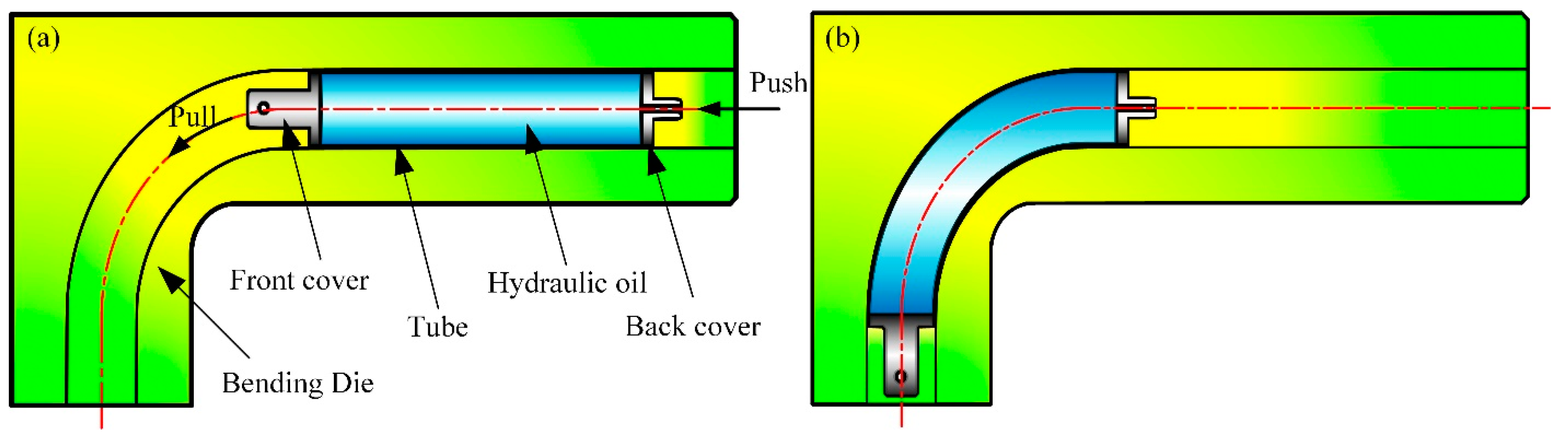
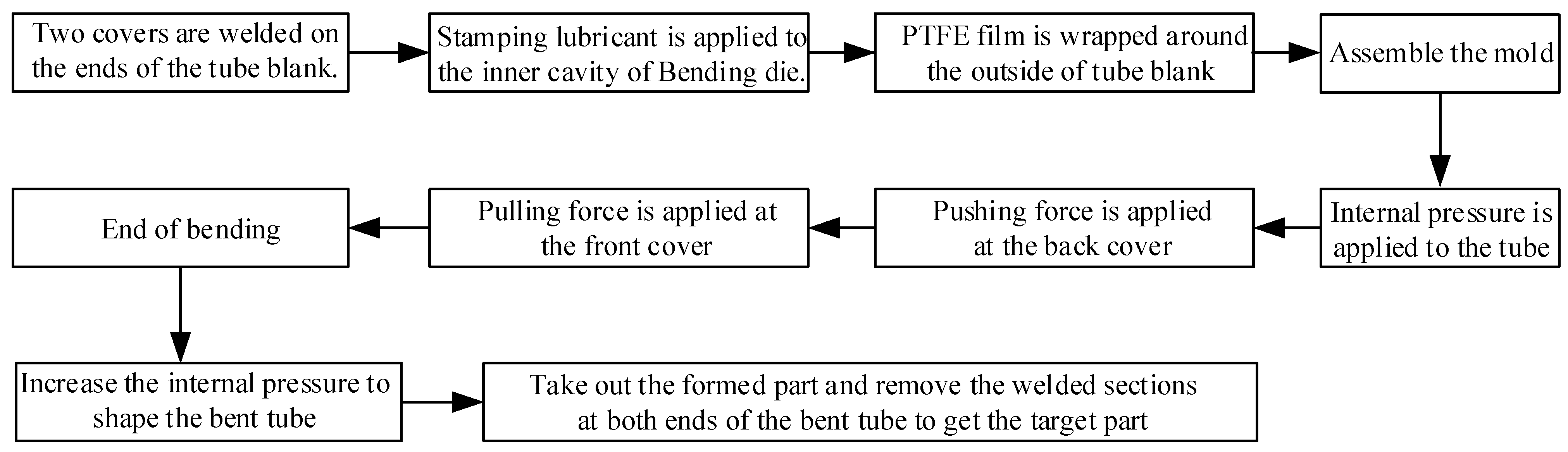
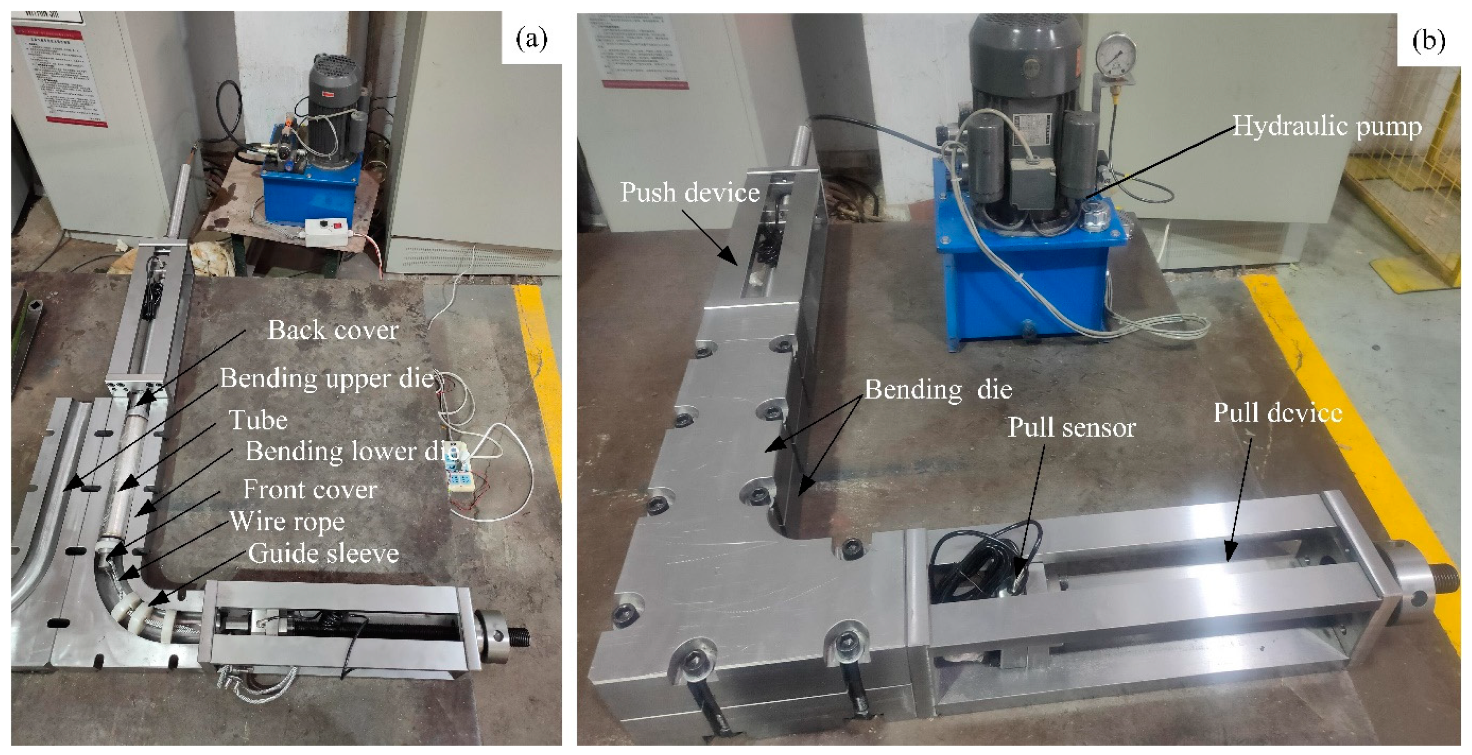
2.1. Forming Process

The schematics of the ultra-thin-walled tube hydraulic push-pull bending process are illustrated in Figure 1. Two covers were welded on the ends of the tube blank to seal the hydraulic oil, then they were placed into the bending die. The front cover bulge had a hole to connect the pull device. The center of the back cover was provided with a through hole that was used to connect the hydraulic system by pipelines, and the threads on the back cover were linked with the push device. The tube was loaded at both ends during bending, while the hydraulic system provided internal pressure. The flow diagram of the hydraulic push-pull bending process is shown in Figure 2. According to the actual tube bending process, the combination of pushing force, pulling force, and internal pressure can be adjusted to achieve the optimal forming effect. The tube blank under internal pressure partially offset the tendency of cross-sectional flattening during bending. Furthermore, the axial push advanced the metal flow on the outer side of bent tube to replenish materials, which slowed the tube wall thinning. The axial pull partially counteracted the compressive stress on the inner side of tube, and reduced the tendency of the inner wall to thicken or wrinkle. In addition, the tube blank could be bent and formed in the mold cavity, which suppressed the unloading rebound and cross-section distortion. The process proposed in this paper had suppressive effects on all four defects of tube bending.

2.2. Finite Element Simulation
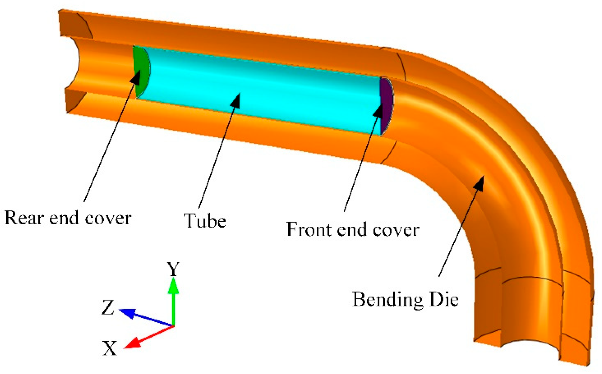
2.2.1. Modeling

As shown in Figure 3, the 3D FE model of the ultra-thin-walled tube hydraulic push-pull bending process was built, including a bending die, tube, and two covers. Numerical simulations were carried out using ABAQUS/Explicit (2019, Dassault Systemes, Providence, Johnston, RI, USA). The bending die and covers were predefined as discrete and rigid, and the tube was set as a shell. The geometric parameters of the bending process are shown in Table 1.

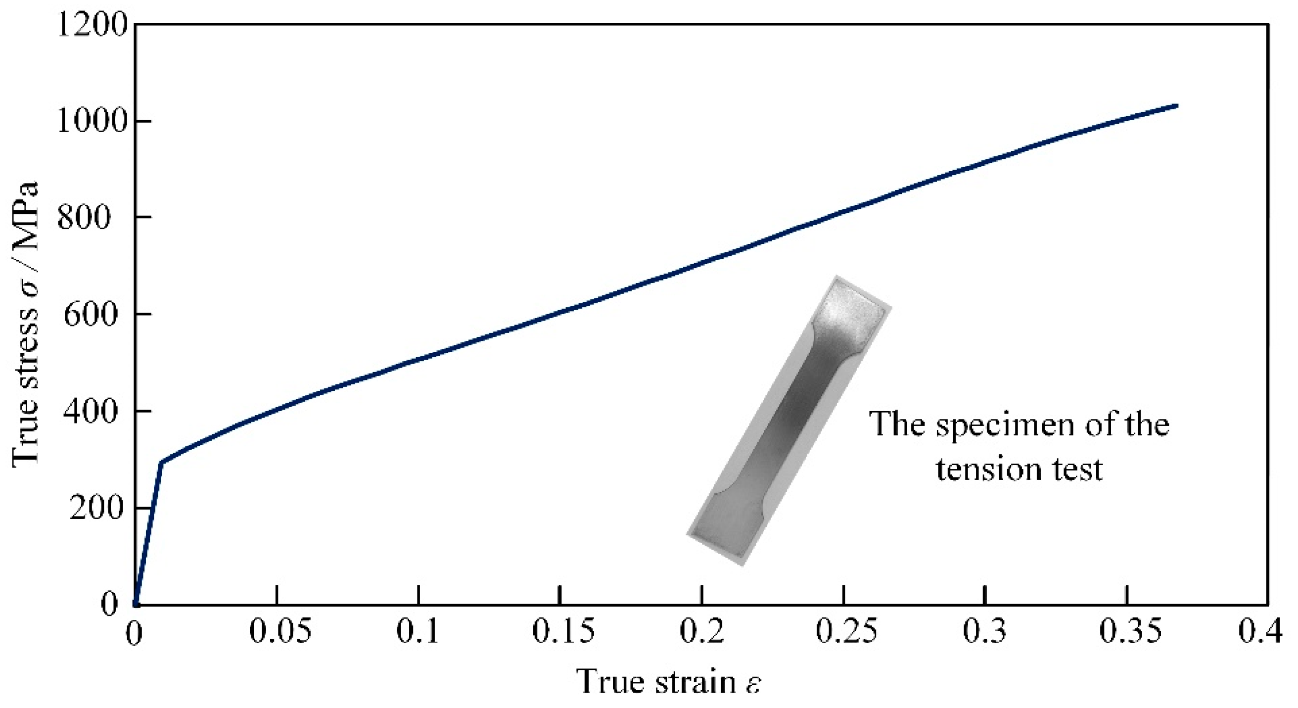
2.2.2. Material Properties

A uniaxial tensile test at the speed of 3 mm/min was carried out on the specimens cut from the 0Cr18Ni9 stainless steel sheet. The true stress-strain curve of the 0Cr18Ni9 stainless steel sheet is shown in Figure 4 and its mechanical properties are presented in Table 2.

2.2.3. Interactions, Boundary Conditions, and Meshes

The tube–die and cover–die contacts were modeled using surface-to-surface contact. The friction behavior in the FE model was described using the Coulomb friction model. The bending die was fixed, and the covers were connected to the tube with ties. Constant pushing force was applied at the back cover and rotational displacement was applied at the front cover to ensure that the rotation center of the tube was consistent with the bending center of the die. When the t/D of the tube is less than 0.05, the tube is meshed with a four-node, doubly curved, thin shell S4R, which has the features of reduced integration and hourglass control (to avoid shear locking) [5]. Therefore, considering the t/D of the tube in this study was 0.005, the tube was meshed with S4R. Five integration points were selected across the shell thickness and the number of meshes for the tube was 14,100.

3. Results and Discussion of Simulation

Many factors affect the hydraulic push-pull bending process. The influence of internal pressure, die clearance, and the friction coefficient on the forming quality of bent tube are mainly discussed in this paper. As shown in Figure 5, the deformation area of the tube blank after bending 90° was evenly divided into 30 parts from 0° to 90°, then the nodes were numbered from 0 to 30. The wall thickness of each node on the intrados and extrados of the bent tube was measured. In addition, as shown in Figure 6, cross-sections were selected every 15° in the deformation area of the bent tube and the ovality, φ, of cross-sections A, B, C, D, E, F, and G was calculated. The formula is as follows:
φ = D m a x D m i n D ,
where, D is the initial diameter of tube blank, Dmin is the minimum outer diameter of the cross-section of bent tube, and Dmax is the maximum outer diameter of the cross-section of bent tube.
The intrados and extrados wall thickness and cross-section ovality are taken as indicators to measure the forming quality of the bent tubes.

3.1. The Influence of Internal Pressure on the Hydraulic Push-Pull Bending Process

During bending, the intrados wall thickness of the bent tube increased and wrinkling instability occurred due to the tangential compressive stress. Under the action of the bending moment, the extrados wall thickness of the bent tube was reduced due to the tangential tensile stress and produced rigid movement in the direction of the bending center, which leads to cross-section distortion and even collapse. Therefore, the tube blank is often filled with different mediums to suppress bending defects during production. In this paper, uniform internal pressure was applied to the inner wall of the tube blank by hydraulic oil to support the cross-section. The expression of the minimum internal pressure to reduce distortion is as follows:
P = 2 t D σ s ,
where, P is the internal pressure, D is the diameter of tube blank, t is the initial wall thickness of tube blank, and σs is the yield stress.
The selection of internal pressure can be guided according to Equation (2). In order to explore the influence of internal pressure on the forming quality of bent tubes in detail, different internal pressures of 2 MPa, 4 MPa, 6 MPa, and 8 MPa were simulated in this paper. The friction coefficient between the tube blank and bending die was 0.05, and the unilateral gap between the outer wall of the tube blank and the inner wall of the bending die was 0.8 mm. When the internal pressure was 2 MPa, it was not enough to support the bending deformation of the tube blank. The wrinkling of the bent tube was due to insufficient internal pressure, as shown in Figure 7.
Figure 8 shows the wall thickness variation of the intrados and extrados of bent tube under different internal pressures. The wall thickness of the front part of the tubes was thinned due to the pulling force; however, the back part of tubes was thickened due to the pushing force. The outer wall of the bent tube was thinned while the inner wall of the bent tube was thickened.
When the internal pressure was 2 MPa, the wall thickness fluctuated greatly due to serious wrinkling on the inner side. The wrinkling on the inner side of tube was suppressed when the internal pressure was increased to 4 MPa, 6 MPa, and 8 MPa, as the radial support force to the tube increased. The wall thickness distribution of nodes 10–25 in the middle of the bent tube was more uniform under the same internal pressure. A smaller thickening of the inner wall thickness and greater thinning of the outer wall thickness was observed with the increase of internal pressure.
At 2 MPa internal pressure, wrinkling and severe distortion of the cross-section appeared in the bending area, and the poor fit of bent tube to the mold resulted in a maximum ovality value of 20%. No significant cross-section distortion of the bent tube appeared when the internal pressure was increased to 4 MPa, 6 MPa, and 8 MPa. As shown in Figure 9a, the ovality of the 0° and 90° positions of the bent tube were smaller due to the welding with covers, while the ovality of the 15° and 75° positions were more variable due to the push force and pull force. The best mold fit and the lowest ovality occurred at 45° in the middle of the bent tube. The ovality of cross-sections at different internal pressures decreased with increasing internal pressure, indicating that the increase of internal pressure could suppress the cross-section distortion. Figure 9b shows the variation curve of the pull force with simulation time during tube bending. It can be seen that the pull force tended to increase as the internal pressure was increased, which was due to the increased friction between tube and mold. The pull force remains mostly constant for the same internal pressure.
Comprehensive analysis showed that the small internal pressure was insufficient to support the smooth bending of the tube and serious wrinkling defects would occur, while an increase of internal pressure could effectively suppress the generation of wrinkling defects on the inner side of the tube. The larger the internal pressure, the better the performance of tube ovality. Excessive internal pressure will cause a serious thinning of the outer side of the bent tube and an increase in pull force and friction between the tube and the mold cavity, which will contribute to lower tube forming quality as well as aggravate the damage to the inner wall of the mold and reduce its service life. In addition, high internal pressure places higher demands on the seal. Therefore, either too large or too small internal pressure is not the best choice for the hydraulic push-pull bending process. On the premise of ensuring tube forming quality requirements, combined with the actual production experience, an internal pressure of 4 MPa was used in this paper.

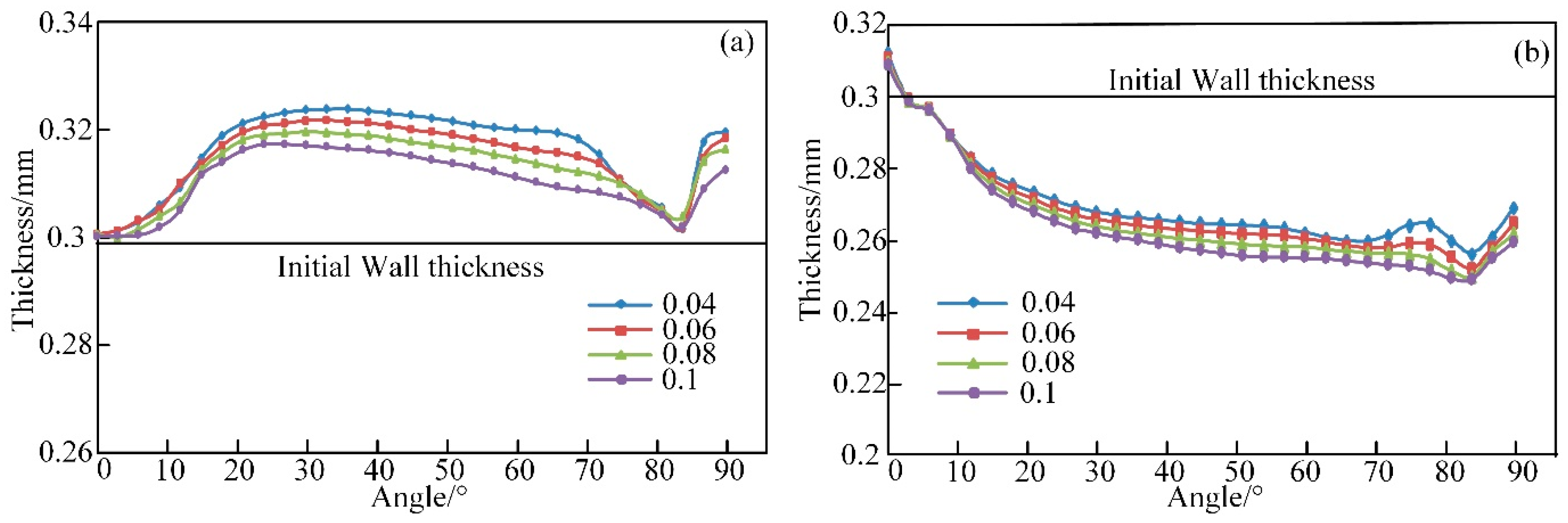
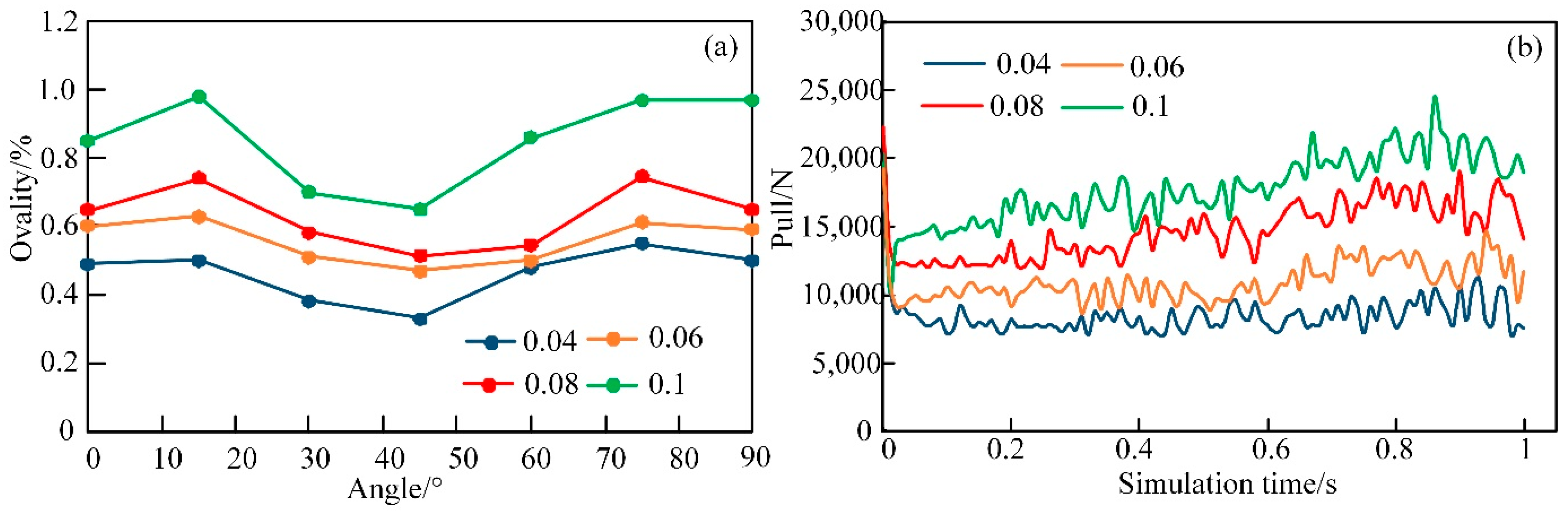
3.2. The Influence of Friction on the Hydraulic Push-Pull Bending Process

To investigate the effect of friction between the tube and the mold on bending formability, friction coefficients of 0.04, 0.06, 0.08, and 0.1 were simulated in this paper. Internal pressure was uniformly set to 4 MPa and the clearance between the outer wall of tube and the inner cavity of mold was 0.8 mm. Figure 10 shows the wall thickness curves of the inner and outer sides of the tubes with different friction coefficients. It can be seen that the inner wall thickness of the tube tends to thicken, and the outer wall thickness tends to thin. The tendency of inner wall thickness thickening of the bent tube was reduced as the friction coefficient was increased, as shown in Figure 10a, which indicated that increasing the friction coefficient helped to suppress the inner wall thickness thickening. The outer wall thickness variation is shown in Figure 10b. Increased friction led to an increased pull force in the bending process, which aggravated the thinning of the outer side; therefore, the outer wall thickness is more greatly affected by friction.
Figure 11 shows the variation of ovality of cross-sections A, B, C, D, E, F, and G and the alteration of pull force during the forming process with different friction coefficients. It can be observed that the ovality and pull force increased as the friction coefficient increased.
The effect of the friction coefficient on wall thickness is similar to the effect of internal pressure. The increased friction coefficient limited the thickening of the inner side, and aggravated the thinning of the outer wall thickness. In addition, the growth of friction will increase the pull force, which can easily cause cross-section distortion and ovalization. In actual production, high friction may reduce the service life of a mold and the surface quality of the bent tubes. However, high lubrication conditions and high production costs are required for a low friction coefficient. In a comprehensive analysis, a friction coefficient of 0.06 was more appropriate.

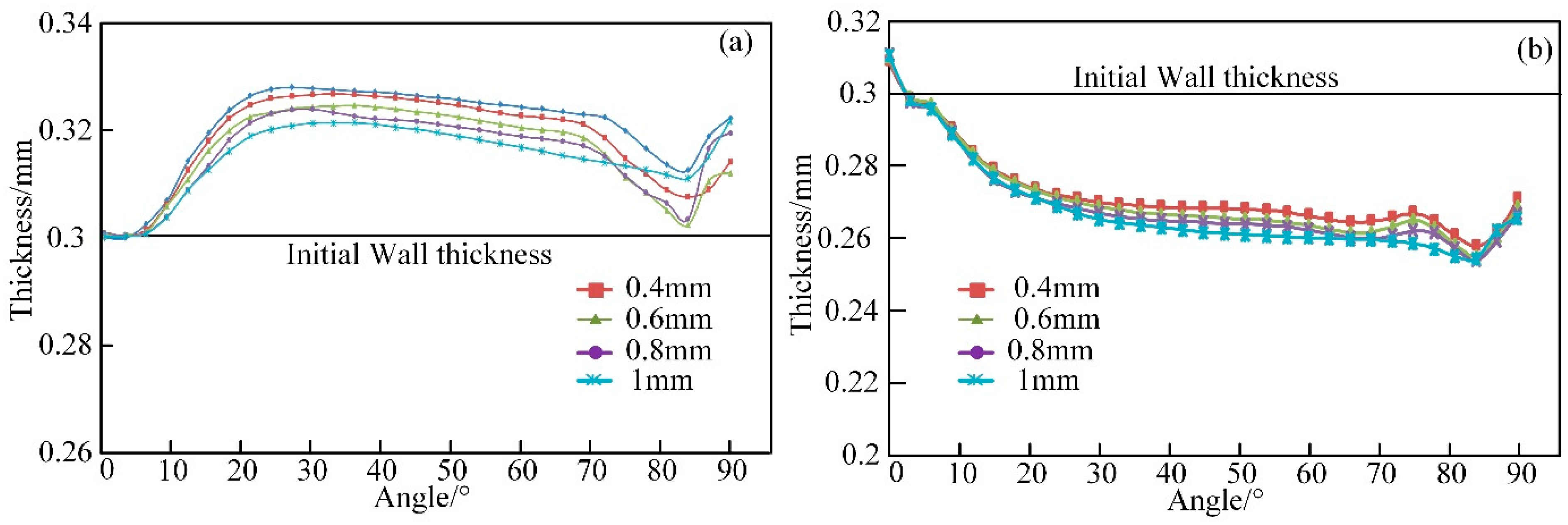
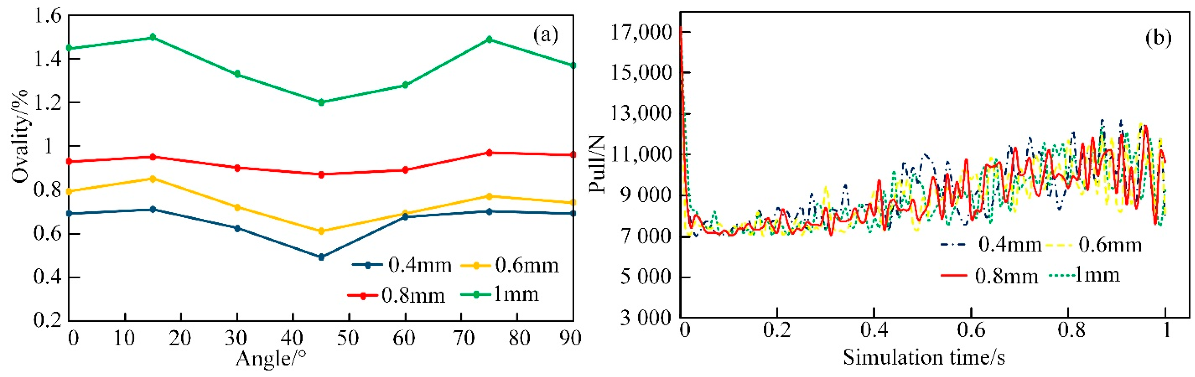
3.3. The Influence of Die Clearance on the Hydraulic Push-Pull Bending Process

In actual production, there inevitably exists manufacturing tolerances in the diameter of the tubes and the bending mold consists of an upper and lower half-die. Therefore, there was clearance between the outer wall of the tube and the inner cavity of the mold after the mold closed, which greatly affected the forming quality of the bent tube. In this paper, clearance values of 0.4 mm, 0.6 mm, 0.8 mm, and 1 mm were selected to investigate the effect of clearance on tube forming quality by simulation. The internal pressure was 4 MPa and the friction coefficient was 0.06.
It can be seen from Figure 12 that the inner side of the bent tube thickening reduced while the outer side thinning increased with the growth of the mold gap. The reason for this was that the material of the tube blank flowed smoothly in the bending process when the gap grew. Variation of inner wall thickness was more uniform, while the outer wall thickness was thinned severely due to the poor fit to the mold.
As shown in Figure 13a, the ovality of cross-sections at different angles showed an increasing trend as the gap increased, and the maximum value was closed to 1.5%.
A large radial space was created during tube bending due to the great gap, therefore the cross-section deformed more easily. Figure 13b shows a small change in pull force with different gaps.
The existence of clearance is inevitable. Increased clearance leaves space for wrinkle instability and section deformation of the tube during bending; therefore, the clearance between the tube and die should be minimized. However, too little clearance requires higher processing accuracy of the mold and increases the production cost; thus, a clearance of 0.8 mm was chosen in this paper.
Considering the effects of internal pressure, friction, and die clearance, the best simulation parameters for 0Cr18Ni9 stainless steel ultra-thin-walled tube (t/D = 0.005) with a wall thickness of 0.3 mm, diameter of 60 mm, bending radius of 165 mm, and bending angle of 90° are: an internal pressure of 4 MPa, a friction coefficient of 0.06, and die clearance of 0.8 mm. These parameters satisfy the industrial requirements and take into account economic benefits.

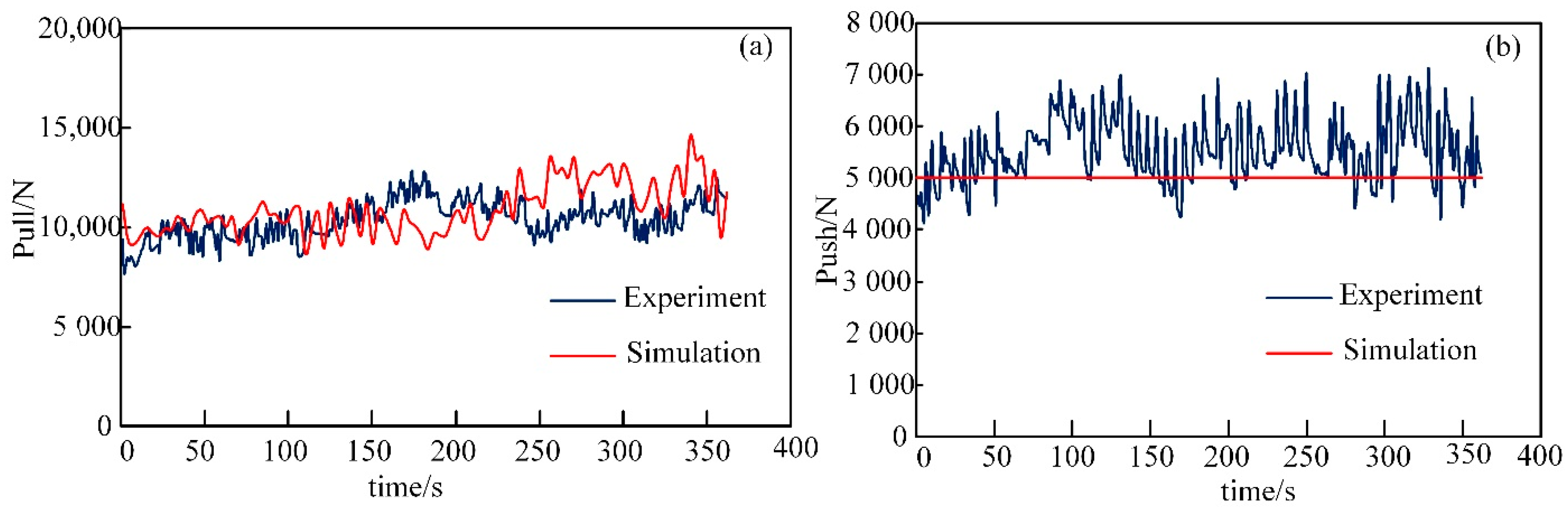
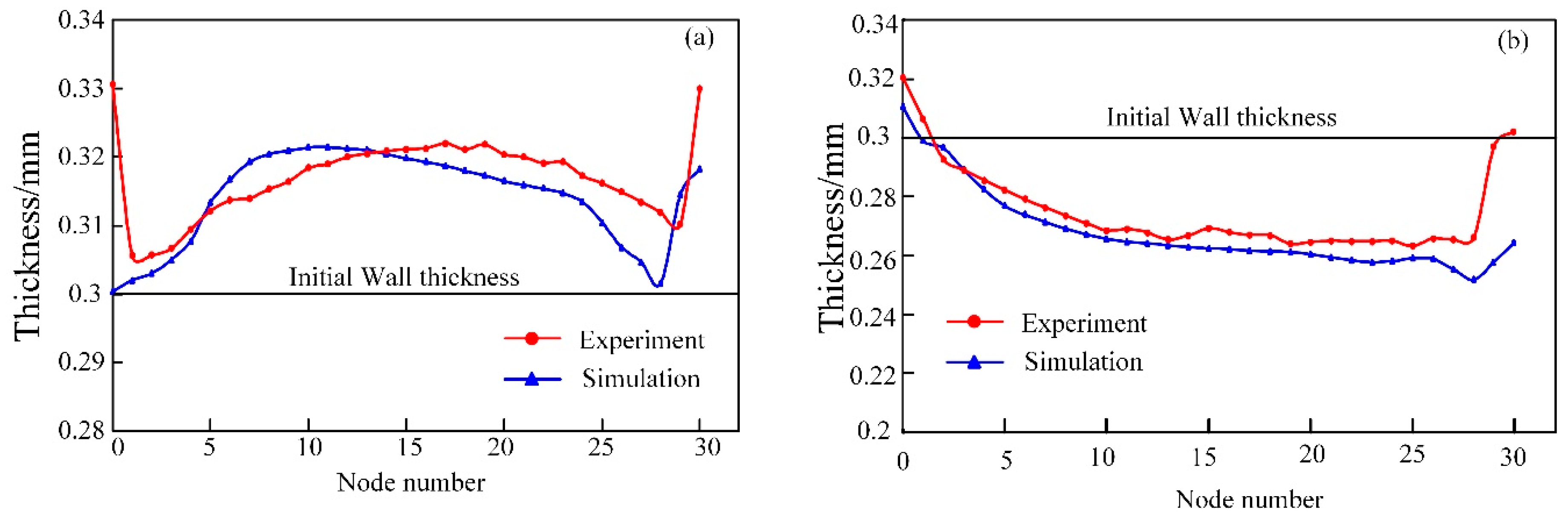
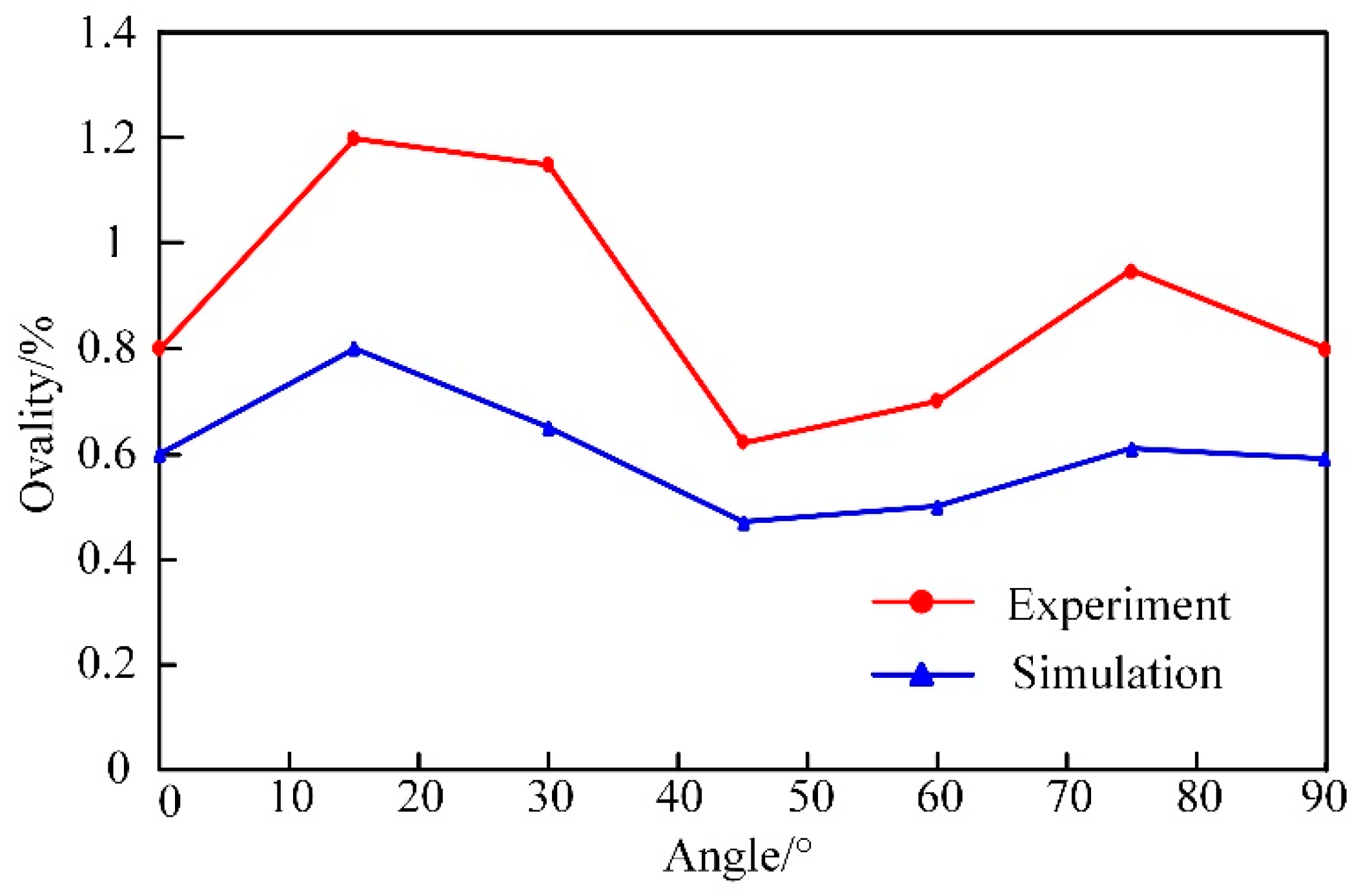
4. Experimental Verification

To verify the simulation results, an experimental mold was designed that consisted of four main parts, including the bending die, push device, pull device, and hydraulic pump station, as shown in Figure 14. The hydraulic pump station consisted of a hydraulic pump, drive motor, oil tank, relief valve, reversing valve, etc. The sensor was a spoke pull and pressure sensor, and the push and pull force was applied by the screw drive system. The experimental tube blanks were 0Cr18Ni9 stainless steel rolled welded tubes with a diameter of 60 mm, thickness of 0.3 mm, and length of 300 mm. The lubricant used in the experiment was stamping lubricant, and PTFE film was wrapped around the outside of tube blank to minimize friction. When the internal pressure was 4 MPa, a bent tube that conformed to processing requirements was obtained. A comparison between the simulation and experiment of the formed part is shown in Figure 15.
A comparison of the results from experimental and simulation pull force and push force is shown in Figure 16. It can be seen that the experimental push and pull forces were in good fit with the simulation. The inner and outer wall thickness of the experimental bent tube was measured with an ultrasonic thickness gauge, and the comparison of experimental and simulation results is shown in Figure 17.
The ovality of bent tubes is also an important reference for industry to determine whether the tubes are qualified products. The ovality of the experimental bent tubes was measured at 15° intervals. A comparison of measurement results and simulation results is shown in Figure 18. It could be seen that the law was mostly consistent, but the experimental bent tubes were subject to experimental conditions. For example, the screw drive system providing the pull force was unable to ensure that the direction was always along the central axis of the mold cavity, which would increase the ovality of cross-sections. In addition, the method of measurement also contributed to errors. However, the maximum ovality of the experimental bent tubes was 1.2%, which satisfied the actual industrial production requirement (less than 5%).

5. Conclusions

This paper proposed a hydraulic push-pull bending process with a large bending radius and large bending angle. A finite element model considering internal pressure, friction, and clearance was established. The accuracy of the FE simulation was verified through the comparative analysis of experiment and simulation, and the following conclusions were obtained.
(1)
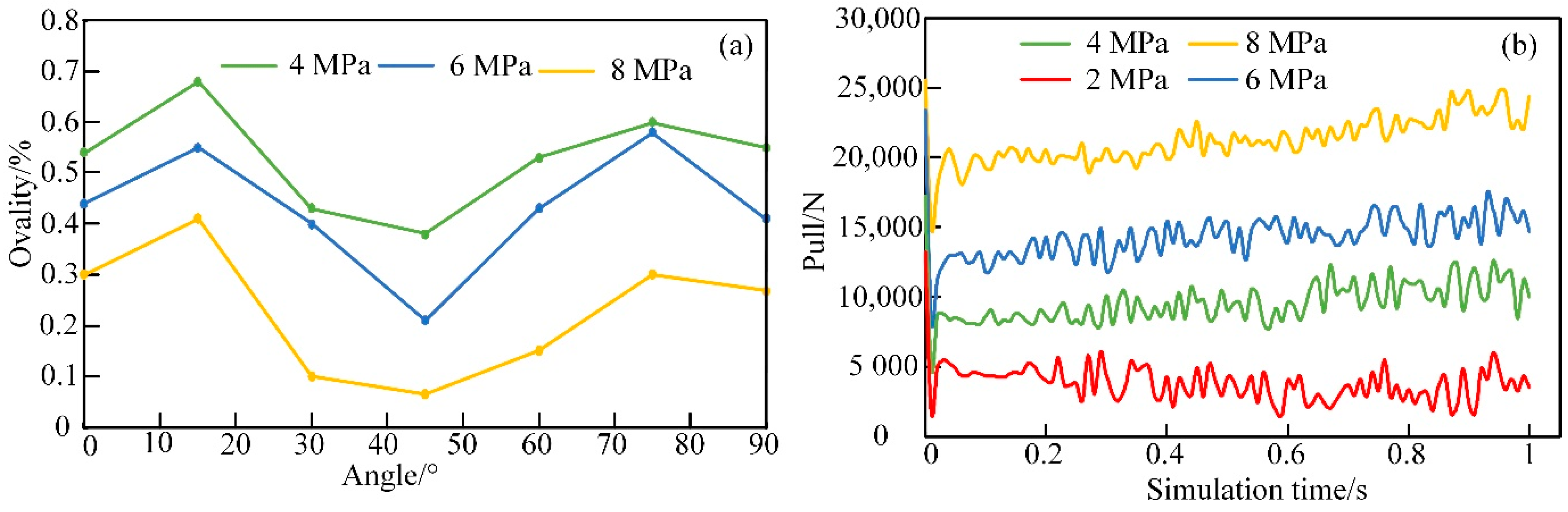
Wrinkling and cross-section deformation tend to occur when bending an ultra-thin-walled tube. However, wrinkling and cross-section deformation can be suppressed by increasing internal pressure.
(2)
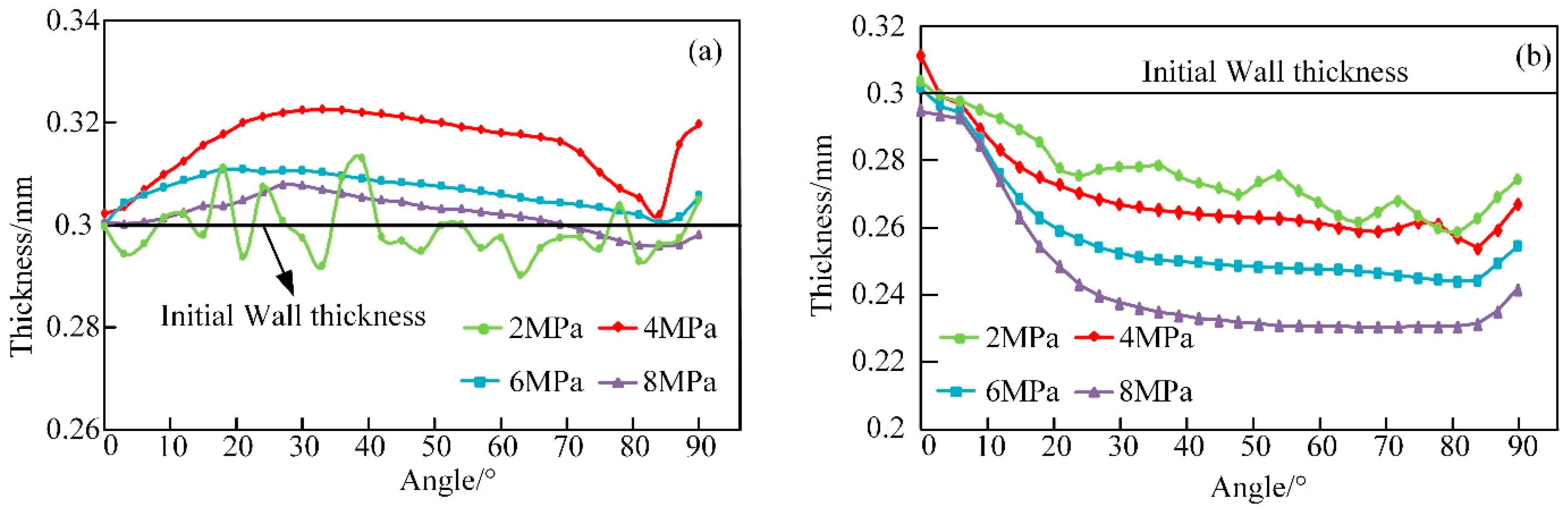
Large internal pressure, friction, and die clearance can suppress the increase of inner wall thickness of the bent tube but worsen the thinning of outer wall thickness. The optimal process parameters of 4 MPa internal pressure, 0.06 friction coefficient, and 0.8 mm die clearance were determined by the simulation.
(3)
The bent tubes with an initial wall thickness of 0.3 mm, diameter of 60 mm, bending radius of 165 mm, and bending angle of 90° were successfully obtained through the experiments and the accuracy of the finite element model was verified.

Author Contributions

Conceptualization, X.Z.; methodology, X.Z.; software, X.Z.; validation, X.Z.; investigation, X.Z.; data curation, X.Z.; experiment, X.Z. and Z.H. writing—original draft preparation, X.Z.; writing—review and editing, D.C. and Y.L.; supervision, C.Z. and B.D.; funding acquisition, C.Z. All authors have read and agreed to the published version of the manuscript.

Funding

This research was funded by the National Natural Science Foundation of China (Grant No. 52175367), the Natural Science Foundation of Hebei Province (Grant No. E2020203181), and the National Natural Science Foundation of China (Grant No. 51605420).

Institutional Review Board Statement

Not applicable.

Informed Consent Statement

Not applicable.

Data Availability Statement

Not applicable.

Conflicts of Interest

The authors declare no conflict of interest.

References

  1. Yang, H.; Li, H.; Zhang, Z.Y.; Zhan, M.; Liu, J.; Li, G.J. Advances and trends on tube bending forming technologies. Chin. J. Aeronaut. 2012, 25, 1–12. [Google Scholar] [CrossRef] [Green Version]
  2. Hashmi, S. Comprehensive Materials Processing; Elsevier: Amsterdam, The Netherlands, 2014; pp. 321–350. [Google Scholar]
  3. Totten, G.E.; Tiryakioğlu, M.; Kessler, O. Encyclopedia of Aluminum and Its Alloys; CRC Press: Boca Raton, FL, USA, 2019; pp. 2732–2750. [Google Scholar]
  4. Liu, N.; Yang, H.; Li, H.; Yan, S.L. Plastic wrinkling prediction in thin-walled part forming process: A review. Chin. J. Aeronaut. 2016, 29, 1–14. [Google Scholar] [CrossRef] [Green Version]
  5. Liu, N.; Yang, H.; Li, H.; Tao, Z.J.; Hu, X. An imperfection-based perturbation method for plastic wrinkling prediction in tube bending under multi-die constraints. Int. J. Mech. Sci. 2015, 98, 178–194. [Google Scholar] [CrossRef]
  6. Li, H.; Yang, H.; Zhan, M. A study on plastic wrinkling in thin-walled tube bending via an energy-based wrinkling prediction model. Model. Simul. Mater. Sci. Eng. 2009, 17, 035007. [Google Scholar] [CrossRef]
  7. Limam, A.; Lee, L.H.; Corona, E.; Kyriakides, S. Inelastic wrinkling and collapse of tubes under combined bending and internal pressure. Int. J. Mech. Sci. 2010, 52, 637–647. [Google Scholar] [CrossRef]
  8. Gholipour, J.; Worswick, M.J.; Oliveira, D. Application of Damage Models in Bending and Hydroforming of Aluminum Alloy Tube; SAE Technical Paper; SAE International: Warrendale, PA, USA, 2004. [Google Scholar] [CrossRef]
  9. Li, H.; Yang, H.; Zhan, M. A Study on critical thinning in thin-walled tube bending of al-alloy 5052O via coupled ductile fracture criteria. In AIP Conference Proceedings; American Institute of Physics: College Park, MD, USA, 2010; Volume 1252, pp. 1286–1294. [Google Scholar]
  10. Safdarian, R. Investigation of tube fracture in the rotary draw bending process using experimental and numerical methods. Int. J. Mater. Form. 2020, 13, 493–516. [Google Scholar] [CrossRef]
  11. Liu, H.; Zhang, S.H.; Song, H.W.; Shi, G.L.; Cheng, M. 3D FEM-DEM coupling analysis for granular-media-based thin-wall elbow tube push-bending process. Int. J. Mater. Form. 2019, 12, 985–994. [Google Scholar] [CrossRef]
  12. Song, H.W.; Xie, W.L.; Zhang, S.H.; Jing, W.H.; Lăzărescu, L.; Banabic, D. Granular media filler assisted push bending method of thin-walled tubes with small bending radius. Int. J. Mech. Sci. 2021, 198, 106365. [Google Scholar] [CrossRef]
  13. Xu, X.F.; Wu, K.W.; Wu, Y.W.; Fu, C.L.; Fan, Y.B. Push-bending method development of thin-walled tube with relative bending radius of 1 using sectional elastomers as mandrel. Int. J. Adv. Manuf. Technol. 2019, 105, 995–1008. [Google Scholar] [CrossRef]
  14. Jiang, W.H.; Xie, W.L.; Song, H.W.; Lazarescu, L.; Zhang, S.H.; Banabic, D. A modified thin-walled tube push-bending process with polyurethane mandrel. Int. J. Adv. Manuf. Technol. 2020, 106, 2509–2521. [Google Scholar] [CrossRef]
  15. Bai, L.; Liu, J.; Wang, Z.; Zou, S.G. Optimal Design of the Shape of a Non-Ball Mandrel for Thin-Walled Tube Small Radius Cold Bending. Metals 2021, 11, 1221. [Google Scholar] [CrossRef]
  16. Lăzărescu, L. Effect of internal fluid pressure on quality of aluminum alloy tube in rotary draw bending. Int. J. Adv. Manuf. Technol. 2013, 64, 85–91. [Google Scholar] [CrossRef]
  17. Montazeri, S.; Gorji, A.; Bakhshi, M. A new method for compression bending of thin-walled tubes in hydro-bending process. Int. J. Adv. Manuf. Technol. 2016, 85, 557–571. [Google Scholar] [CrossRef]
  18. Yasui, H.; Miyagawa, T.; Yoshihara, S.; Furushima, T.; Yamada, R.; Ito, Y. Influence of internal pressure and axial compressive displacement on the formability of small-diameter ZM21 magnesium alloy tubes in warm tube hydroforming. Metals 2020, 10, 674. [Google Scholar] [CrossRef]
  19. Wang, J.; Agarwal, R. Tube bending under axial force and internal pressure. J. Manuf. Sci. Eng.-Trans. ASME 2006, 128, 598–605. [Google Scholar] [CrossRef]
  20. Zeng, Y.S.; Li, Z.Q. Experimental research on the tube push-bending process. J. Mater. Process. Technol. 2002, 122, 237–240. [Google Scholar] [CrossRef]
  21. Oh, I.Y.; Han, S.W.; Woo, Y.Y.; Ra, J.H.; Moon, Y.H. Tubular blank design to fabricate an elbow tube by a push-bending process. J. Mater. Process. Technol. 2018, 260, 112–122. [Google Scholar] [CrossRef]
  22. Baudin, S.; Ray, P.; Mac Donald, B.J.; Hashmi, M.S.J. Development of a novel method of tube bending using finite element simulation. J. Mater. Process. Technol. 2004, 153–154, 128–133. [Google Scholar] [CrossRef]
  23. Goodarzi, M.; Kuboki, T.; Murata, M. Effect of initial thickness on shear bending process of circular tubes. J. Mater. Process. Technol. 2007, 191, 136–140. [Google Scholar] [CrossRef]
  24. Goodarzi, M.; Kuboki, T.; Murata, M. Deformation analysis for the shear bending process of circular tubes. J. Mater. Process. Technol. 2005, 162–163, 492–497. [Google Scholar] [CrossRef]
  25. Teng, B.G.; Hu, L.; Yuan, S.J. Deformation behavior of thin-walled tube bending with internal pressure. Rev. Adv. Mater. Sci. 2013, 33, 436–441. [Google Scholar]
  26. Hu, L.; Teng, B.; Yuan, S.J. Effect of internal pressure on hydro bending of double-layered tube. Proc. Inst. Mech. Eng. Part B J. Eng. Manuf. 2012, 226, 1717–1726. [Google Scholar] [CrossRef]
  27. Nakajima, K.; Utsumi, N.; Saito, Y.; Yoshida, M. Deformation Property and Suppression of Ultra-Thin-Walled Rectangular Tube in Rotary Draw Bending. Metals 2020, 10, 1074. [Google Scholar] [CrossRef]
Figure 1. Schematics of the ultra-thin-walled tube push-pull bending process with hydraulic oil (a) before bending and (b) after bending.
Metals 11 01932 g001
Figure 2. Flow diagram of hydraulic push-pull bending process.
Metals 11 01932 g002
Figure 3. Schematic of the simulation model of hydraulic push-pull bending.
Metals 11 01932 g003
Figure 4. True stress-strain curve of 0Cr18Ni9 sheet blank.
Metals 11 01932 g004
Figure 5. Illustration of wall thickness measurement location.
Metals 11 01932 g005
Figure 6. Schematic diagram of tube cross-section after bending.
Metals 11 01932 g006
Figure 7. Wrinkling of the bent tube due to insufficient internal pressure in (a) FE simulation and (b) experiment.
Metals 11 01932 g007
Figure 8. Wall thickness of bent tube with different internal pressures at the (a) intrados and (b) extrados.
Metals 11 01932 g008
Figure 9. The (a) ovality of bent tubes and (b) pull of the bending process with different internal pressures.
Metals 11 01932 g009
Figure 10. Wall thickness of bent tube with different friction coefficients at the (a) intrados and (b) extrados.
Metals 11 01932 g010
Figure 11. The (a) ovality of bent tubes and (b) pull of bending process with different friction coefficients.
Metals 11 01932 g011
Figure 12. Wall thickness of bent tube with different clearance at the (a) intrados and (b) extrados.
Metals 11 01932 g012
Figure 13. The (a) ovality of bent tubes and (b) pull of bending process with different clearance.
Metals 11 01932 g013
Figure 14. Experimental device (a) internal structure and (b) assembly diagram.
Metals 11 01932 g014
Figure 15. Comparison of bending results from (a) FE simulation and (b) experiment.
Metals 11 01932 g015
Figure 16. The comparison of experimental and simulation results of (a) pull force and (b) push force.
Metals 11 01932 g016
Figure 17. Experimental and simulated bending wall thickness of (a) intrados and (b) extrados.
Metals 11 01932 g017
Figure 18. Comparison of ovality between experiment and simulation.
Metals 11 01932 g018
Table 1. Geometric parameters of bending process.
Tube Diameter
D/mm
Tube Thickness
t/mm
Tube Length
L/mm
Bending Angle
θ
Bending Radius
R/mm
600.330090165
Table 2. Mechanical properties of 0Cr18Ni9 sheet blank.
Density
ρ/(g·cm−3)
Young’s Modulus
E/GPa
Poisson’s Ratio
ν
Tensile Yield Strength
σs/MPa
Ultimate Tensile Strength
σb/MPa
Elongation
δ/%
7.932010.3291103342
Publisher’s Note: MDPI stays neutral with regard to jurisdictional claims in published maps and institutional affiliations.

