Review

Recent Progress in Understanding the Nano/Micro-Mechanical Behavior of Austenite in Advanced High Strength Steels

1
Shenzhen Key Laboratory of Cross-Scale Manufacturing Mechanics, Southern University of Science and Technology, Shenzhen 518055, China
2
Department of Mechanical and Energy Engineering, Southern University of Science and Technology, Shenzhen 518055, China
3
Institute for Manufacturing Innovation, Southern University of Science and Technology, Shenzhen 518055, China
*
Authors to whom correspondence should be addressed.
Metals 2021, 11(12), 1927; https://doi.org/10.3390/met11121927
Submission received: 28 October 2021 / Revised: 25 November 2021 / Accepted: 26 November 2021 / Published: 29 November 2021

Abstract

:
Advanced high strength steels (AHSS) are developed to reduce vehicle weight without sacrificing passenger safety. The newly developed AHSS frequently incorporates the austenite as the intrinsic component with large amount and good stability, which is realized by carefully designed alloying elements and thermo-mechanical processing. To explore the great potential of austenite in enhancing the strain hardening behavior of AHSS, detailed information on the mechanical behavior of single austenite grain is a prerequisite, which can be collected by a small-scale test. The present work reviews the recent progress in understanding the nano/micro-mechanical behavior of austenite in varied AHSS. Three different plasticity modes including dislocation plasticity, martensitic transformation, and deformation twinning can be observed in the austenite grains during small-scale tests, given proper stacking fault energy and crystal orientation. The remaining issues concerned with the nano/micro-mechanical behavior of austenite are discussed. The present review advances the general understanding of the nano/micro-mechanical behavior of austenite grains in AHSS, which may shed light on the precise austenite engineering with the development of new AHSS, realizing the dream of high-performance steels at low cost.

1. Introduction

The advanced high strength steels (AHSS) are developed to overcome the trade-off between the reduction of vehicle weight and the increase of passenger crashworthiness [1]. The ultrahigh strength of AHSS allows the design of thinner structural components and lighter automobiles while protecting the passengers from the anti-intrusion events [2]. The good ductility of AHSS ensures the large energy absorption during the central collision, the easy fabrication of complex structural components, and the observed deformation before the sudden failure [2].
The AHSS has undergone three generations of development since the 1970s. The 1st generation of AHSS generally contains the single or dual ferritic phases, with the famous one known as dual-phase (DP) steel, which is deemed as the savior of the Detroit automotive industries [3]. The 2nd generation of AHSS has a single austenitic phase with the formation of deformation twins to enhance work hardening capability during plastic deformation, which is generally known as the twinning induced plasticity (TWIP) steel [4]. With a meticulous alloy design strategy associated with the precisely controlled thermo-mechanical processing, the mechanical property (strength and ductility) of 3rd generation of AHSS has reached a new high level in the recent decades, realizing the dream of high-performance steel at low cost [5,6]. It generally incorporates dual-phase microstructure including ferritic and austenitic phases, with typical steel grades known as carbide free bainitic (CFB) steel [7,8], medium Mn steel [9,10,11], and quenching and partitioning (Q&P) steel [12,13]. The concept of Q&P steel is proposed by Prof. Speer [12] and is initially industrialized by Baosteel. The common component in the 3rd generation of AHSS is the austenite phase, which is a high-temperature stable phase. Nevertheless, it can be reserved at room temperature through alloying or partitioning of the austenite stabilizers such as C and Mn during the fabrication process [10,14,15].
Different from the single dislocation plasticity in most of the 1st generation of AHSS (except for the transformation induced plasticity (TRIP) assisted multiphase steel), the austenite grains in 2nd and 3rd generation of AHSS demonstrate different kinds of plasticity during the plastic deformation, including the dislocation plasticity, transformation-induced plasticity, and/or twinning-induced plasticity [16]. The operation of multiple plasticity modes effectively alleviates the conflicts between the strength and ductility (also known as the strength-ductility trade-off) in the AHSS containing metastable austenite grains [17,18]. The strengthening derived from the operation of multiple plasticity modes in the austenite grains can be simply ascribed to the increased dislocation density of steel grades [19]. Taking the martensitic transformation as an example, the instantaneously generated dislocations owing to the martensitic transformation in retained austenite grains is the direct contribution to the enhanced work hardening (increased dislocation density) [20]. The presence of martensite/austenite interface owing to the formation of martensite separates the prior austenite grains into different grain sizes, serving as the strong barrier for dislocation motion, indirectly promoting the dislocation density and thus the enhancement of work hardening behavior [21]. The heterogeneous distribution of hard martensite in soft austenite matrix leads to the deformation inhomogeneity, which is accommodated by the pile-up of the geometrically necessary dislocations (GND) at the interface, improving the work hardening capacity [22]. The kinetics of martensitic transformation in individual austenite grains determines the effectiveness of dynamic strain partitioning in enhancing the work hardening behavior [23]. However, the austenite grains in the AHSS generally have small grain size (<5 μm) which are consequently difficult to be investigated by macroscopic characterization techniques (i.e., tensile test) [24]. In contrast, the small-scale test is capable to capture the mechanical response of the ultrafine austenite grains in the AHSS. Since the first report of nanoindentation test on the single austenite grains of TRIP-assisted multiphase steels in 2001 [25], there is a growing interest in studying the nano-mechanical behavior of the austenite in AHSS [26,27,28,29,30,31,32]. Moreover, the increasing interest in understanding the small volume mechanical behavior is backed up by the potential emerging industrial application such as micro-electro-mechanical systems (MEMS) [33].
Currently, there is a substantial volume of review papers covering the different aspects of AHSS, including the bulk mechanical behavior [34,35,36,37,38], thermo-mechanical processing [24,39], phase transformation [40], and microstructure-guided design [41,42]. However, to the best of our knowledge, the review work on the nano/micro-mechanical behavior of austenite in AHSS is still lacking in the open literature. To this end, the present review incorporates the extensive research works on the nano/micro-mechanical behavior of austenite in AHSS, with an aim to provide the state-of-the-art of research status in this emerging field. Most of the investigations on the nano-mechanical behavior of the ultrafine austenite grains employ the sharp indenter such as the Berkovich indenter. Nevertheless, for relatively large austenite grain size, the fabrication of the micro-pillar of a single austenite crystal is possible. The compression of the micro-pillar with a flat indenter can avoid the generation of the GNDs in the single austenite crystal during the plastic deformation [43]. Therefore, irrespective of the deformation types (geometry of the indenter), the present review covers the recent progress on the investigation of the nano/micro-mechanical response of the individual austenite grains in AHSS. The concluding remarks are provided to address the remaining issues on this topic.

2. Austenite in AHSS

The austenite grains in the 3rd generation of AHSS demonstrate the different microstructural features which are determined by the presence of varied defects, including the point defects (interstitial/substitutional atoms), line defects (dislocations), and area defects (stacking faults/twins/boundary) [23]. Among these defects, the grain boundary is the most important one as it determines the domain, size, and morphology of the austenitic single crystal for the storage of other defects. In general, the defects in austenite grains are derived from prior phase transformation during the thermo-mechanical processing. The austenite grains in Q&P steel demonstrates blocky and film-like morphologies (Figure 1a) [44], which is related to the extent of the martensitic transformation. In particular, the extensive martensitic transformation leads to the severe partition of prior austenite grain into film-like retained austenite while the moderate martensitic transformation results in the co-existence of blocky and film-like residual austenite. The above observation is also applicable for the austenite grains in the CFB steel considering the displacive nature of bainitic transformation (Figure 1b) [45]. The number of defects in the retained austenite grains including dislocations, stacking faults, and deformation twins depends on the extent of phase transformation. The austenite grains retained after displacive shear transformation (martensitic/bainitic transformation) are deformed to accommodate the transformation strain of the adjacent transformed products [46]. The defect density in austenite grains is heterogeneous owing to the localized deformation process, demonstrating increased defect density with the decrease of distance to the interface of austenite and product phase [47]. Since the blocky austenite grains are subjected to less extensive martensitic transformation, they are expected to have lower amounts of internal defects than that of filmy-like counterparts. The retained austenite grains in medium Mn steel are generally obtained by reverse transformation from either quenched or deformed martensite, generating the lamellar or granular austenite grains, respectively (Figure 1c) [48]. In addition, the morphology of austenite grains in medium Mn steel also depends on the extent of reverse transformation. The reverse transformation from ferritic phase to austenite with different durations results in austenite grains with either lamellar or granular morphology [49]. Although the mechanism of reverse transformation deviates from the displacive shear transformation, the lamellar austenite grains in medium Mn steel exhibit higher dislocation density than the granular counterpart, which can be rationalized from the concurrence of dislocations recovery or recrystallization with prolonged duration [50].
The phase transformation is frequently associated with element partitioning between the ferritic and austenitic phases during the thermo-mechanical processing of 3rd generation of AHSS. Owing to the relatively low partitioning temperature in Q&P steel and the low bainitic transformation temperature in CFB steel, only the C partitioning from the ferritic phase to the austenite phase is observed while the Mn partitioning is negligible [12,51]. In contrast, the intercritical annealing temperature is sufficiently high to allow both Mn and C partitioning in the medium Mn steel [10,14,15]. The element enrichment (C, Mn), dislocations, and ultrafine grain size are all contributing to the stabilization of austenite grains at ambient temperature [10,14,15]. Therefore, the austenite grains in the 3rd generation of AHSS demonstrate unique microstructural features as compared to the ferritic counterpart, including the different morphologies, higher interstitial/substitutional elements, and heterogeneous distribution of dislocations.
Different from the complex phase transformation and element partitioning involved in the processing of the 3rd generation of AHSS, only typical recrystallization, and dislocation recovery is necessary for the fabrication of 2nd generation of AHSS (i.e., TWIP steel as shown in Figure 1d) [52,53]. The grain size of the austenite can be tuned by controlling the austenitization temperature and durations. The heterogeneous grained structure with twinned and untwined austenitic phase can be generated in TWIP steel (Fe-22Mn-0.6C in wt.%) by employing the severe plastic deformation and subsequent controlled annealing at 600 °C with partial recrystallization [54]. The prolonged aging treatment of deformed TWIP steel at 400 °C for 336 h may lead to the decomposition of austenite into pearlite at the highly deformed regions with intensive cementite precipitations [54]. The nanotwined steel can be produced by cold deformation of the TWIP steel system (Fe-17.59Mn-0.75C-1.7Al-0.52Si in wt.%) with the generation of deformation twins and dislocations, followed by dislocation recovery process to regain the strain hardening capacity [55]. The phase transformation is absent during the cold deformation of TWIP steel and the cementite precipitation can be avoided by reducing the duration of recovery annealing such as 500 °C for 15 min [55].

3. Nano/Micro-Mechanical Behavior of Austenite

Different from the single dislocation plasticity in ferritic phases, the plastic deformation of the austenite in AHSS during small-scale test is realized by the multiple plastic modes, including the dislocation plasticity, martensitic transformation, and deformation twins. For dislocation plasticity in the face-centered cubic (FCC) austenitic phase, there are 12 available slip systems including the 4 possible <011> slip directions and 3 potential {111} slip planes, where the selection of specific slip systems is governed by the Schmid factor. The operation of other competing plasticity mechanisms in the austenite grains is closely connected to the dislocation activities. For instance, the separation of perfect dislocations into two partial dislocations are connected by a ribbon known as stacking faults (SF), which is the precursor for the initiation of deformation twins [63,64]. The distance of two partial dislocations corresponds to the width of stacking faults which is inversely proportional to the stacking fault energy (SFE). The operation of different plasticity modes in austenite grains depends on the value of SFE, which is governed by deformation temperature and chemical composition [65,66]. According to a thermal dynamic model established for a Fe-Mn-C alloying system [65], the martensitic transformation operates for SFE lower than 18 mJ/m2, the deformation twinning occurs for SFE between 12 and 35 mJ/m2, and dominant dislocation plasticity takes place for SFE higher than 40 mJ/m2 [65]. Although the exact value of SFE is varied among different models [65,67,68], these studies can qualitatively describe the correlation between the SFE and the operation of the different plasticity modes. Interestingly, it has been shown that the value of SFE does not continuously increase with the Mn content [67]. There is a minimum value of SFE with respect to the Mn content, beyond which the value of SFE increases with the increase of Mn content. According to the estimation of plasticity modes based on the value of SFE, it is expected that both martensitic transformation and deformation twins can be operative for a SFE in a range of 12–18 mJ/m2 [65]. Irrespective of the multiple plasticity modes in austenite grains with proper SFE, the dislocation slip is frequently the dominant mechanism for the plastic deformation of the bulk sample, which is partially due to the frequent interaction between the dislocations and boundaries. The nucleation of martensite has been modeled through the arrangement of dislocations and the growth of martensite is facilitated by the motion of glissile transformation dislocations [69]. Nevertheless, the nano/micro-pillars compression test of the austenitic single crystal is dominated by certain plasticity modes other than dislocation slip, such as deformation twins [70], which is affected by the presence of a large surface-to-volume ratio.

3.1. Dislocation Plasticity

The retained austenite grains in most of the 3rd generation of AHSS have ultrafine grain size. The mechanical behavior of these single austenite grains can be investigated by the nanoindentation measurement. In general, the nano-mechanical behavior of austenite in AHSS is reflected from the load-displacement (P-h) curve, based on which the different plasticity modes of austenite can be examined. Like the bulk mechanical behavior of austenite, the deformation of the individual austenite grain during the small-scale tests also incorporates the elastic and plastic deformation. The elastic deformation of the austenite grains is frequently evaluated by the Hertzian elastic contact solution as below [71]:
P = 4 3   E r R i 1 2 h 3 2
where P is the indentation load, Er is the reduced elastic modulus, Ri is the tip radius, h is the penetration depth. Note that the tip of the indenter may not be perfectly sharp, and the tip blunting is unavoidable owing to the wear during frequent usage. The tip radius can be estimated from the radius of contact curvature using the atomic force microscopy (AFM) [72] or by fitting to the well-known metallic materials with the obvious strain burst (or pop-in) event and the well-documented elastic properties. Since both specimen and indenter are subjected to the elastic deformation during the nanoindentation test, the generated modulus from the P-h curve is the reduced elastic modulus (Er) which can be described by elastic properties (E: Young’s modulus, v: Poisson’s ratio) of the specimen (s) and indenter (i) as below [73]:
1 E r = 1 v i 2 E i + 1 v s 2 E s
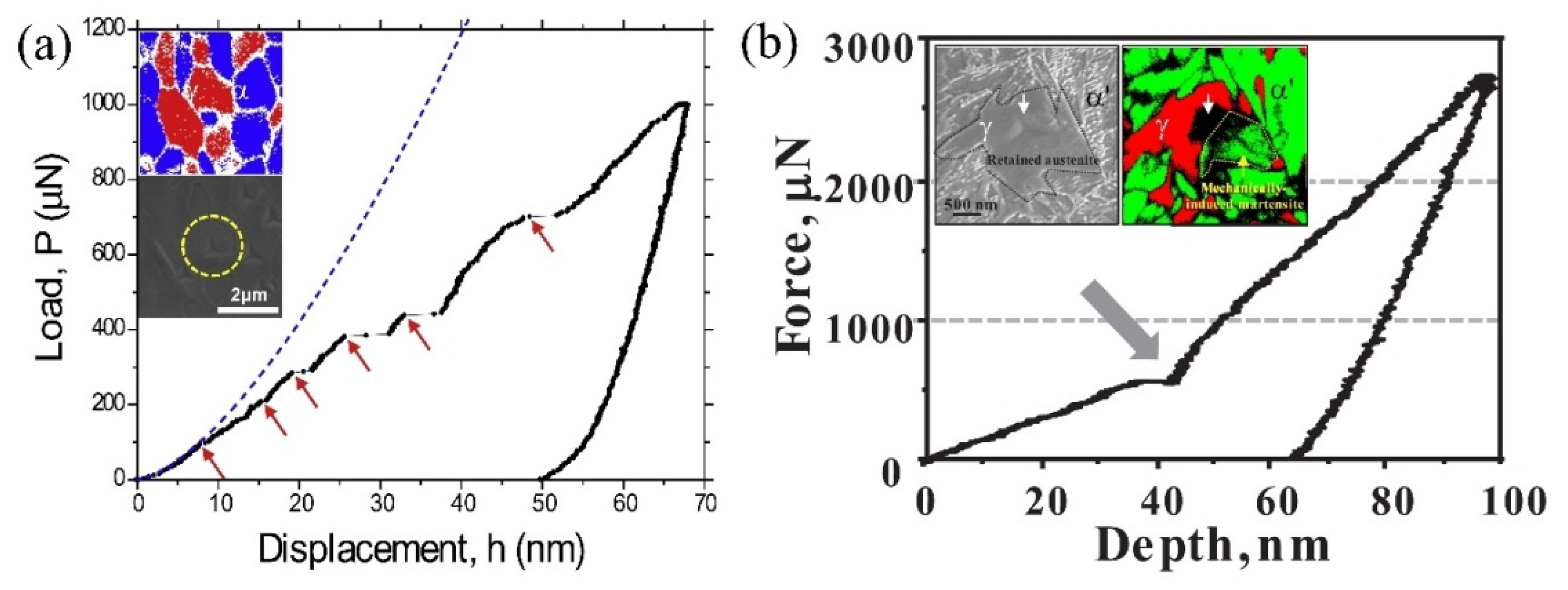
The typical Hertzian elastic contact solution fitted to the P-h curve of the retained austenite grains in medium Mn steel is shown in Figure 2. The discontinuity (strain burst or pop-in) coincides with the deviation of the P-h curve from the Hertzian elastic contact solution in the load-controlled nanoindentation test (Figure 2). Note that both strain burst and load drop are observed for the displacement-controlled mode owing to the machine compliance [74].
The deviation of the P-h curve of austenite grains from the Hertzian elastic contact solution is in the range of 0.1–0.2 mN. The occurrence of such deviation indicates the initiation of plasticity, which is frequently ascribed to the dislocation nucleation (incipient plasticity). The above conclusion is drawn based on the estimation of the maximum shear stress (τmax) underneath the indenter as below [71]:
τ max = 0.31 π ( 6 P E r 2 R i 2 ) 1 3
With the input of the indentation parameters, the τmax can thus be estimated from Equation (3) and it frequently approaches the ideal strength of austenite (G/6~G/30) [75]. Therefore, the dislocations could be nucleated beneath the indenter under the τmax. In other words, the initial pop-ins in P-h curves of austenite may indicate incipient plasticity [76]. Note that not all P-h curves of the austenite grains demonstrate pop-in at the position where the curve deviated from the Hertzian elastic contact solution. The austenite grains in Q&P steel and CFB steel are distributed with the defects resulting from the accommodation process of the displacive shear strain (martensitic or bainitic transformation). The presence of dislocations in the austenite grains in Q&P steel and CFB steel makes the nucleation of dislocations beneath the indenter unnecessary and thus no obvious pop-in for the initiation of plastic deformation. Nevertheless, the austenite grains in the medium Mn steel could be subjected to recrystallization and thus have lower dislocation density, increasing the possibility of indented volume containing no dislocations and thus the required nucleation of dislocations to initiate the plasticity.
The elastic-plastic deformation of the austenite grains is initiated after the deviation of the P-h curve from the Hertzian elastic contact solution. The plastic part of the P-h curve of the austenite grains can be studied by the GND concept using the following equation [77,78]:
P = A c M C β G b ρ S S D + ρ G N D
where Ac = 24.5h2 is the area projected under the ideal Berkovich indenter, M = 3 is the Taylor factor [77], C = 3 is the constraint factor [77], β = 0.5 describes the dislocation structure [77], b = 0.252 nm is Burgers vector of austenite, ρSSD and ρGND are dislocation densities in terms of the statistically stored dislocations (SSD) and GND in the plastic zone, respectively. Considering the small austenite grain size, the maximum indentation depth is generally shallow to avoid the indentation impression across the boundary. Therefore, the ρSSD can be neglected under the low indentation depth. The ρGND can be described by the following equation according to the classic Nix-Gao model as [79]:
ρ G N D = 3 2 1 f 3 tan 2 θ b h
where f describes the proportion of the plastic zone radius (apz) to the contact radius (ac), θ represents the angle between the specimen surface and the indenter. The fitting of the GND concept to the P-h curve of austenite is shown in Figure 2. In general, the overall fitting of the GND concept to the P-h curve can give the value of f, which can be affected by other defects such as the austenite grain boundaries. Considering the ultrafine austenite grain size, the nanoindentation investigation on the austenite grain may involve the influence of grain boundaries. The expansion of the indentation plastic zone with the increase of indentation load may encounter the austenite grain boundary. The high angle grain boundaries can inhibit the dislocation transmission event while the low angle grain boundaries are vulnerable to the transmission of dislocations across the boundaries [80]. The confinement of the dislocations by high angle grain boundaries can limit the indentation plastic zone size, leading to the increased resistance of austenite to penetration of the indenter and thus higher hardness.
The single dislocation plasticity in retained austenite grains in AHSS is difficult to be achieved during the nanoindentation test as there are some other competing deformation mechanisms such as martensitic transformation and deformation twins. Considering the formation mechanism of deformation twins, the single dislocation plasticity can be obtained by employing the crystal orientation of the austenite with the favored generation of perfect dislocation [74,81]. Nevertheless, the martensitic transformation is less affected by the orientation as there are 24 or 12 possible martensitic variants according to the Kurdjumov–Sachs (K-S) or Nishiyama-Wasserman (N-W) orientation relationship [82,83]. The suppression of the martensitic transformation during nanoindentation investigation can be only realized through the direct alloying during casting or by partitioning of elements (C, Mn) and dislocation stabilization during thermo-mechanical processing. The single dislocation plasticity in austenite grains in medium Mn steel during nanoindentation investigation allows the capture of the intrinsic nanohardness [84], which is useful to extract the required mechanical properties for the modeling of the AHSS containing the metastable austenite grains. The intrinsic nanohardness of individual austenite grains in other 3rd generations of AHSS has not been reported as the corresponding martensitic transformation during nanoindentation is difficult to evade.
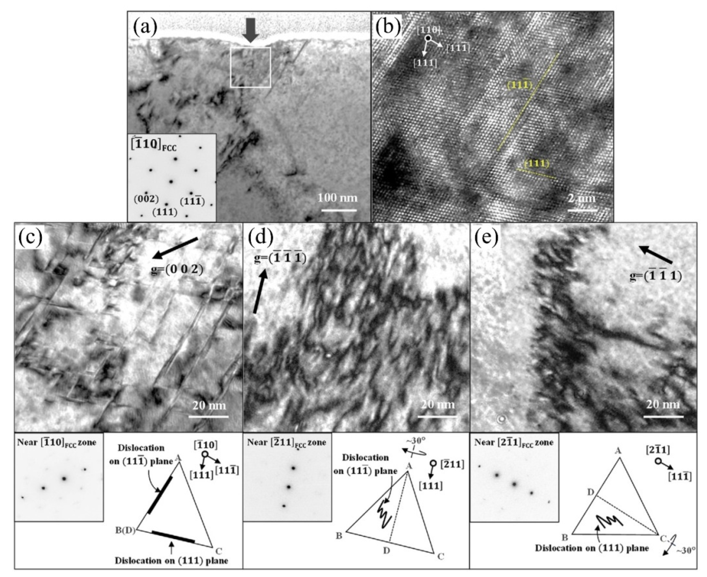
The nano-mechanical behavior of a medium Mn steel (Fe-1.2C-7Mn in wt.%) with a SFE of 28 mJ/m2 has been investigated by the nanoindentation test [81]. Thus, the formation of deformation twins is expected according to the correlation between the SFE and the deformation twins [85]. Nevertheless, the suppression of the deformation twins can be achieved by the selection of the austenite orientation. The single dislocation plasticity is observed for the austenite grains with [111] orientation in a medium Mn steel [81]. TEM observation on the cross-section beneath the indenter reveals the existence of single dislocation plasticity without the formation of deformation twins (Figure 3). The straight lines as shown in Figure 3a are found to be the perfect dislocations rather than the stacking fault (Figure 3b). The detailed observation along different directions (g vectors) confirms the absence of deformation twins beneath the indenter (Figure 3c–e). Only perfect dislocation slip is observed in the austenite grain with [111] orientation [81]. Since the deformation twins are nucleated from three-layer stacking faults resulting from partial dislocations, the difficulty of the disassociation of the perfect dislocations into the partial dislocations is the dominant reason for the single dislocation plasticity during nanoindentation test on the austenite grains with [111] orientation.
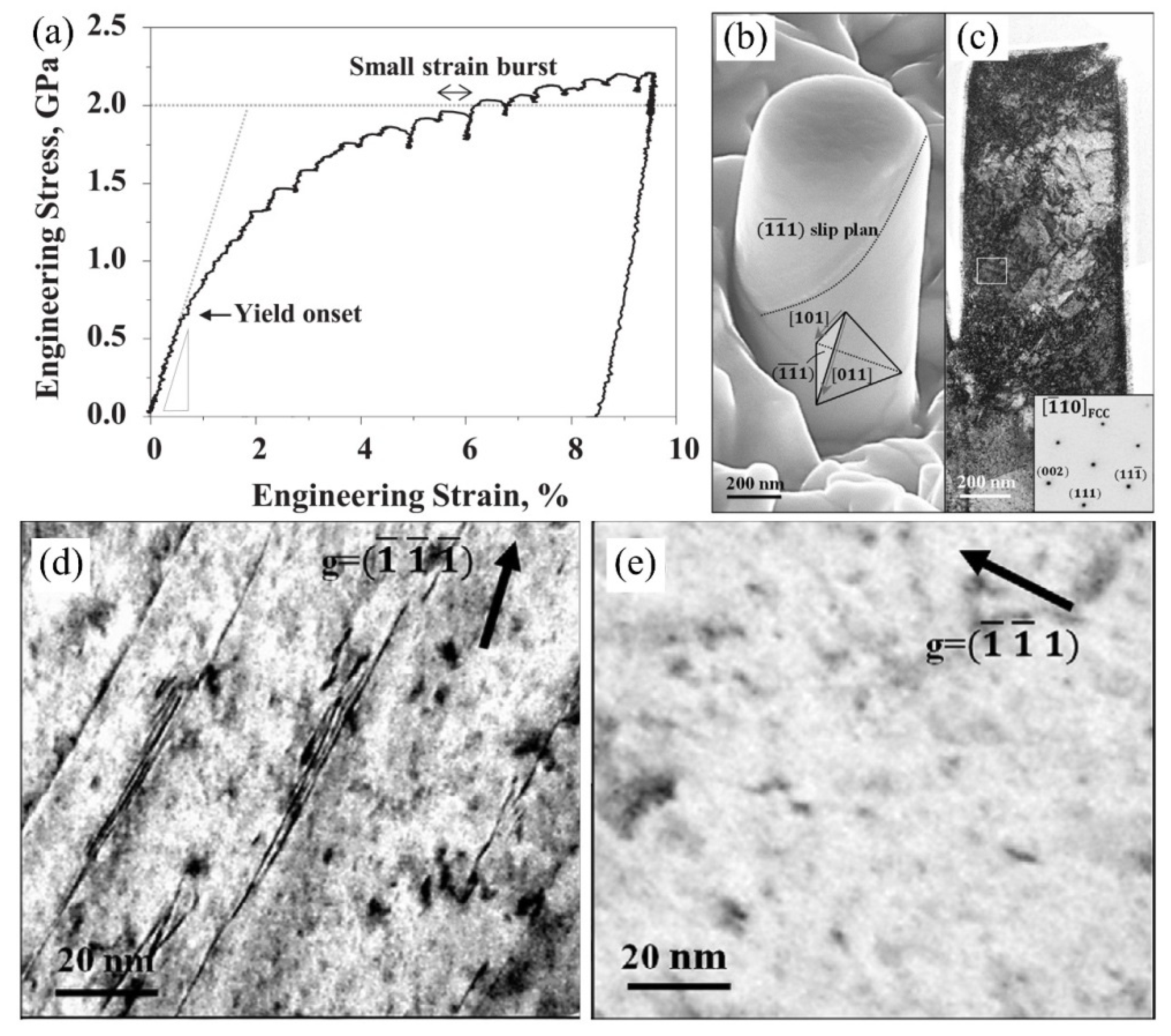
The dislocation plasticity in the single austenite grains can also be investigated by compression test on the micro-pillars. The beneficial aspect of the compression test is the quantitative analysis of the mechanical behavior with the easy extraction of engineering stress–strain curves. Moreover, the generation of the GNDs can be avoided owing to the compression by flat punch [43]. However, different from the nanoindentation measurement armed with a sharp indenter, the micro-pillar compression test requires relatively large austenite grains to fabricate the micron/nano austenitic pillars. Consequently, most of the retained austenite grains in the 3rd generation of AHSS are too small to be suitable for pillar fabrication. Thus, the nano-mechanical behavior of the austenite in the 3rd generation of AHSS is seldom investigated through a pillar compression test [81,86,87]. The size of austenite grains needs to be increased to facilitate the pillar fabrication, which can be realized by high-temperature annealing and the sufficient alloying of austenite stabilizers (Mn, C) as well. The micro-pillar with different diameters can be fabricated by FIB. The avalanche of dislocations after the nucleation leads to jumps (strain bursts) in the stress–strain curves (Figure 4a) [88]. In general, the morphology of the micro-pillar before and after the compression test can be captured by SEM observation. The typical micro-pillar of the austenite along the <111> direction in medium Mn steel after the compression test is shown in Figure 4b. Note that the <111> direction of the austenitic pillar is favorable for the formation of perfect dislocations without the generation of deformation twins, which is consistent with the results observed under the nanoindentation test [81]. Note that this medium Mn steel has a sufficiently high SFE to resist the martensitic transformation (~28 mJ/m2). The formation of perfect dislocations is favored for the austenite with the [111] orientation because a perfect dislocation has smaller critical resolved shear stress as compared to the partial dislocation [81]. The slip traces are evident on the pillar surface as marked with the dashed line in Figure 4c. The arrangement of dislocations in the micro-pillars is inhomogeneous, with intensive dislocations distributed in the upper and lower parts of the deformed pillar (Figure 4c). The dislocations are confined at the top and bottom parts of the pillar owing to the instrumental constraints, leaving the relatively low dislocation density at the center [89]. The perfect dislocations with straight morphology along the (-1 -1 1) slip plane are observed while they disappeared when observed along the different viewing direction according to the g.b = 0 (Figure 4d–e). The single dislocation plasticity is also found in the micro-pillar compression test of a high Mn austenitic steel (Fe-22Mn-0.6C in wt.%) [90], which could be explained by their comparable SFE among these two steel grades. Therefore, the orientation-dependent plasticity of the austenitic pillar is well confirmed. The dislocation plasticity is dominated over the deformation twins and stacking faults for the [111] crystal orientation.

3.2. Martensitic Transformation

The martensitic transformation during plastic deformation is particularly important for the mechanical properties of 3rd generation of AHSS containing metastable austenite grains. The enhancement of strain hardening behavior with the occurrence of martensitic transformation is typically known as the TRIP effect. The performance of martensitic transformation in elevating the work hardening behavior relies on the timing for its occurrence in a single austenite grain, which is usually described by the mechanical stability [23,91]. The understanding of the mechanical stability of single austenite grain helps to design the proper austenite stability for realizing the strength-ductility synergy of AHSS.
Most of the austenite grains in the 3rd generation of AHSS demonstrate the combined plasticity of dislocations and martensitic transformation during the nanoindentation investigation. There are two different pathways for the martensitic transformation, namely γ→α’ transformation and γ→ε→α’ transformation [69,92]. The γ→α’ transformation accompanies a pop-in in the P-h curve (Figure 5). Such pop-in is also observed for ε→α’ transformation [93]. However, no evident pop-in is detected for the γ→ε transformation [93]. Here we mainly focus on the direct γ→α’ transformation during the small-scale test.
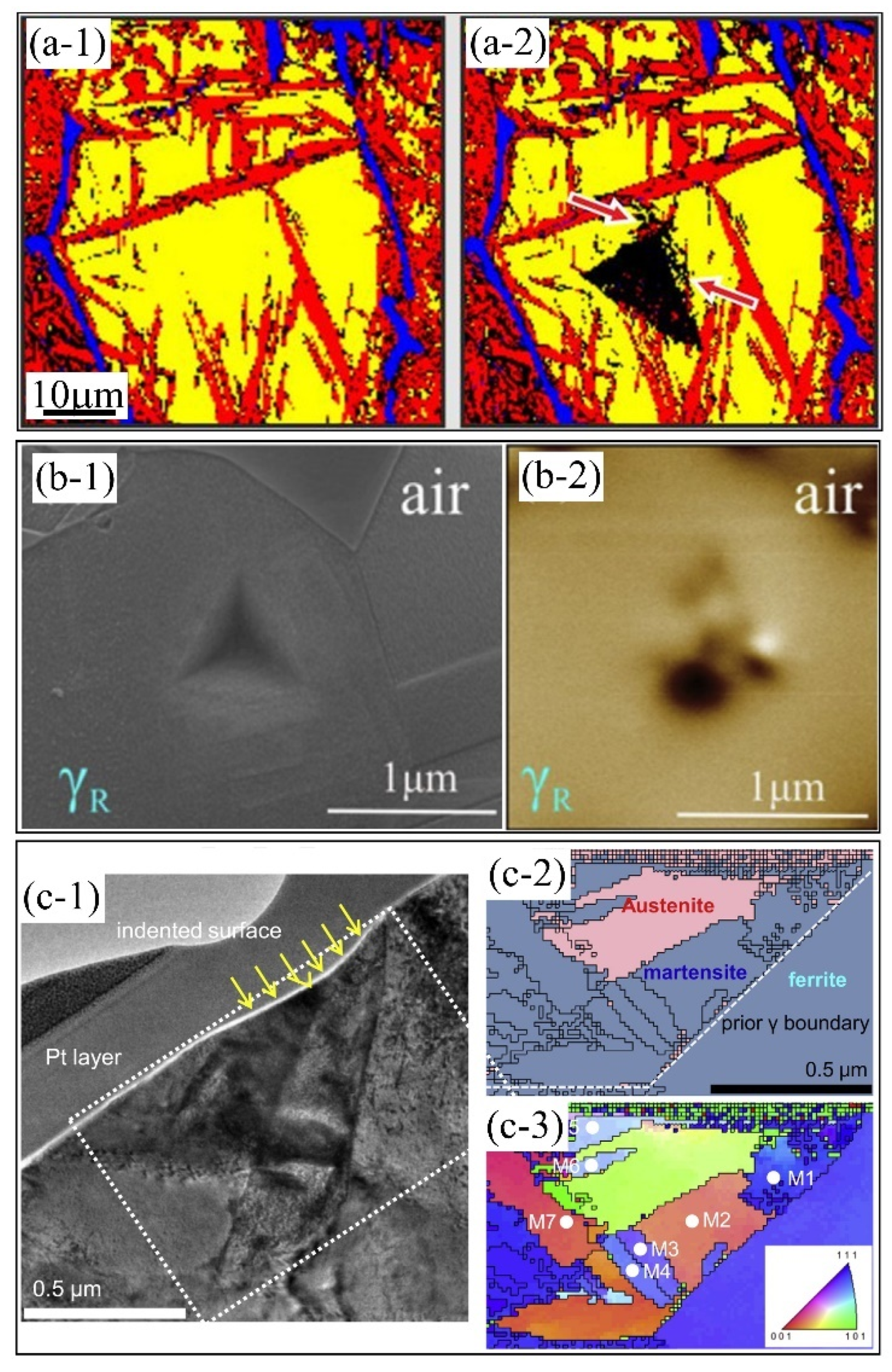
In addition to the occurrence of pop-in, the formation of martensite during nanoindentation measurement can be identified from the microstructural change associated with the indents as well. The identification of martensitic transformation during the nanoindentation test can be realized through the comparison of the phase change before and after the indentation test using the electron backscatter diffraction (EBSD) (Figure 6a) [95,96,97]. Considering that the EBSD observation is only sensitive to the transformed martensite close to the free surface and may resultantly miss the martensite underneath the indenter due to the shallow electron penetration depth, the martensite underneath the indenter can be captured by observation on the thin slide perpendicular to the surface of indented austenite grain prepared by FIB thinning and lift-out strategy [94,98,99]. However, the preparation of the TEM sample made by using the FIB technique may involve the phase transformation induced by radiation [100,101] or by the creation of a free surface [102]. It is reported that magnetic force microscopy (MFM) can verify the boundaries between different magnetic domains (α is ferromagnetic and γ is paramagnetic) [103,104]. Therefore, the change of localized ferromagnetism beneath the indenter can be detected with the generation of possible domain patterns by using MFM imaging (Figure 6b) [105]. Like the EBSD measurement, the MFM can be carried out in a relatively easy and fast way to verify many indents, which is beneficial for statistical analysis [103]. In general, most of the transformed martensite is close to the indenter. Nevertheless, the expansion of the plastic zone may encompass the grain boundaries where the martensite embryo may exist. Consequently, the region close to the grain boundaries could also transform to martensite (Figure 6c).
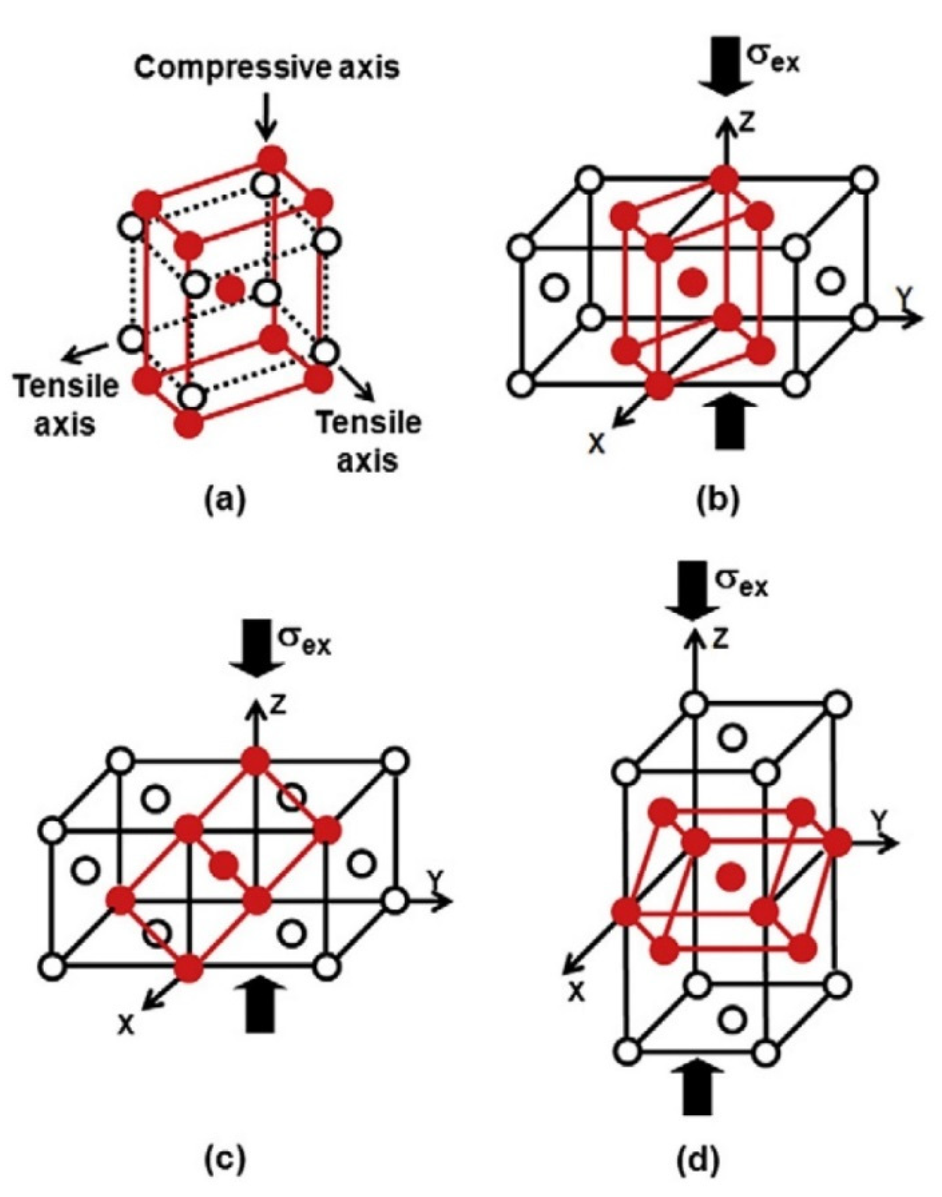
The region beneath the indenter contains the compressive hydrostatic core which is surrounded by the hemispherical plastic zone according to the theoretical consideration [107]. Since the martensitic transformation is dominated by the shear deformation (~0.2) with a minor dilatational exponent (~0.04) [108], the compressive hydrostatic pressure does not interact with the shear strain and shall suppress the volume expansion of martensitic transformation. Therefore, the initiation of martensite shall not be from the hydrostatic core but rather from the plastic zone. In addition, the strain burst represents the geometrical softening, which is inconsistent with the hardening effect of martensite. Therefore, the discontinuity in the P-h curve of indented austenite grains with martensitic transformation is unexpected and should be well explained. The occurrence of the pop-in is ascribed to the martensitic transformation by considering the variant selection during the nanoindentation loading process [94]. There are 24 or 12 possible martensite variants during the nanoindentation test for classic K-S or N-W relation, respectively. To simplify the discussion, the Bain relation is employed to qualitatively explain the strain burst in the P-h curve of metastable austenite grain [99]. The Bain model of martensitic transformation indicates that the martensitic variants accompany one contracted axis and two other expanded axes (Figure 7). The mechanical interaction energy (U), which is a product of the applied external stress (σijD) and the stress–free transformation strain (εijT) [109], assist the nucleation of martensite, and can be rewritten as [110]:
U = σ i j D ε i j T = σ n D ε n T + σ s h D ε s h T
where the invariant-plane strain εijT can be decomposed into normal εnT and shear εshT components. It can be obtained from the phenomenological theory of martensite crystallography (PTMC) [111]. σnD and σshD are the normal and shear stresses perpendicular and parallel to a habit plane (invariant plane) of a martensitic variant, respectively.
The energy barrier for the nucleation of martensite is dominated by the strain energy which should be overcome by the external stress in terms of the mechanical interaction energy. The mechanical interaction energy is varied for different martensitic variants. The martensitic variant with the highest mechanical interaction energy will be selected beneath the indenter [94]. Despite the complex stress field underneath the indenter, the dominant stress state can be considered as compressive [99]. Thus, the martensitic variant with a contraction axis along the indentation direction is selected during the nanoindentation test to maximize the mechanical interaction energy [99]. The velocity for the propagation of martensite is estimated to be around 160–200 m/s in a grain size of 250 μm of a 304 austenitic stainless steel based on the acoustic-emission-frequency spectrum analysis [112]. Note that the propagation velocity is proportional to the austenite grain size. Therefore, it is expected that the propagation velocity is around 0.64–0.8 m/s for austenite with a grain size of 1 μm, which is still too large to be detected by the indenter. Under such circumstances, the indenter tip must have to move further to ensure a fixed loading rate in load-controlled mode, generating a strain burst [99] or reducing the applied load to guarantee a constant strain rate in displacement-controlled mode, inducing either load drop or strain burst for different loading modes [113]. Therefore, the magnitude of pop-in may correspond to the size/volume of the transformed martensite. However, it is difficult to rationalize the magnitude of pop-in with the amount of the transformed martensite as it shall also relate to the orientation of transformed martensite. Considering the phenomenological model of martensitic transformation, the martensitic variant that effectively accommodates the external stress is selected during the nanoindentation test, which is confirmed from the finite element calculation [94].
Among the multiple discontinuities (pop-ins) in the P-h curve, the first pop-in that deviates from the Hertzian contact solution may be induced by the dislocation nucleation [99]. The formation of martensite also initiates a pop-in and mostly takes place after the first one [98]. Therefore, the load at which the second pop-in takes place may represent the critical applied load for initiation of the martensitic transformation [98]. Based on this understanding, the second pop-in load has a positive correlation with the Mn content of austenite grains, which is consistent with the fact that Mn is an austenite stabilizer [98]. The mechanical stability of retained austenite is enhanced by carbon enrichment owing to the carbon partitioning during the tempering treatment [114]. The effect of carbon content on the mechanical stability of austenite is larger than that of the fraction and morphology of austenite in bearing steel [115]. Based on the nanoindentation investigation on the constituting phases, it is reported that the large lenticular martensite is not effective in C partitioning into the adjacent austenitic matrix in a medium Mn steel [116]. The grain size-dependent austenite stability is investigated by the nanoindentation test. The P-h curve of the coarse-grained sample (~12 μm) shows pop-in while no observable pop-in is found in that of the ultrafine-grained sample (~0.65 μm) in 304 L stainless steel [117,118]. However, the conclusions could be questionable as the pop-in event could also be related to the size of the martensite transformed beneath the indenter. In general, the small austenite grain size should also lead to the small martensite, which may not be discernible in the P-h curve. Therefore, a detailed observation of the microstructure beneath the indenter for the UFG specimen is necessary. The stress-induced martensite is found to be ahead of the dislocation plasticity of the transformed martensite in the austenite grains of a high carbon quenched and tempered steel [119]. The decrease of austenite grain size increases the required stress for both martensitic transformation and plastic deformation of transformed martensite, suggesting the small austenite grain has higher mechanical stability than the coarse counterpart [119]. The grain size-dependent nano-mechanical behavior of austenite is investigated with dominated mechanical twinning in nano/ultrafine-grained specimen while the prevalent strain-induced martensite nucleated at the shear bands in the coarse-grained sample during nanoindentation test [120]. The stability of the austenite grains relies on the grain orientation as has been demonstrated in 18CrNiMo7-6 steel [106]. The retained austenite grain with [001] orientation is much less stable as compared to the one with [111] orientation, which is verified by comparing the transformed martensite fraction beneath the indenter [106].
Most of the nanoindentation investigations on the austenite stability involve applying a load beyond the elastic deformation regime [94,98,99]. The formation of martensite in these studies is termed the strain-induced martensitic transformation [99]. However, the stress-induced martensitic transformation is less investigated. The difference between the stress and strain-induced martensite is in their different martensitic nucleation processes [121]. The stress-induced martensite has the same nucleation site as compared to the martensite formed during the quenching process. In contrast, strain-induced martensite refers to the nucleation of martensite at the site created during the plastic deformation process (i.e., intersection of slip bands) [122]. The stress-induced martensite is investigated by applying an ultralow load within the elastic deformation regime. The martensitic transformation takes place adjacent to the annealing twin boundaries. The applied elastic stress facilitates the martensitic transformation through the mechanical interaction energy to overcome the nucleation barrier [95]. The nano-mechanical behavior of individual austenite grain is affected by the geometry of the indenter. The nanoindentation with the cube cone indenter favors mechanical twinning while the Berkovich indenter generates a single martensitic transformation, which is rationalized through the sharper indenter (smaller centerline-to-face-angle) induces a higher shear stress for the generation of deformation twins [97]. The above experimental observation can also be explained by the fact that the sharper indenter corresponds to the higher representative strain and thus this may induce the different mechanical responses of austenite during the nanoindentation test.
The blocky retained austenite exhibits intermediate nanohardness values, which is lower than high-carbon martensite but is larger than bainite in bainitic steels [123]. Nevertheless, it is found that carbon enriched austenite demonstrates a nanohardness comparable to the primary low carbon martensite in Q&P steel [28]. The high nanohardness of the austenite grains is contributed by the martensitic transformation beneath the indenter through either the plastic deformation of the martensite or the dispersion hardening [98], depending on the distance of the transformed martensite to the indenter. It is found that the nanohardness of deformation-induced martensite in CrMnNi steel with a high alloying element is only 24% higher than the parent austenitic matrix [124]. Furthermore, it is concluded that the strain hardening from the martensitic transformation is induced by the dynamic Hall-Petch effect owing to the presence of intensive boundaries from transformed martensite rather than by the “intrinsic” hardness from the deformation of martensite. Nevertheless, the above conclusion is debatable in that the parent austenitic matrix could also be strengthened by the underneath martensite (dispersion hardening), making it slightly softer than the transformed martensite.
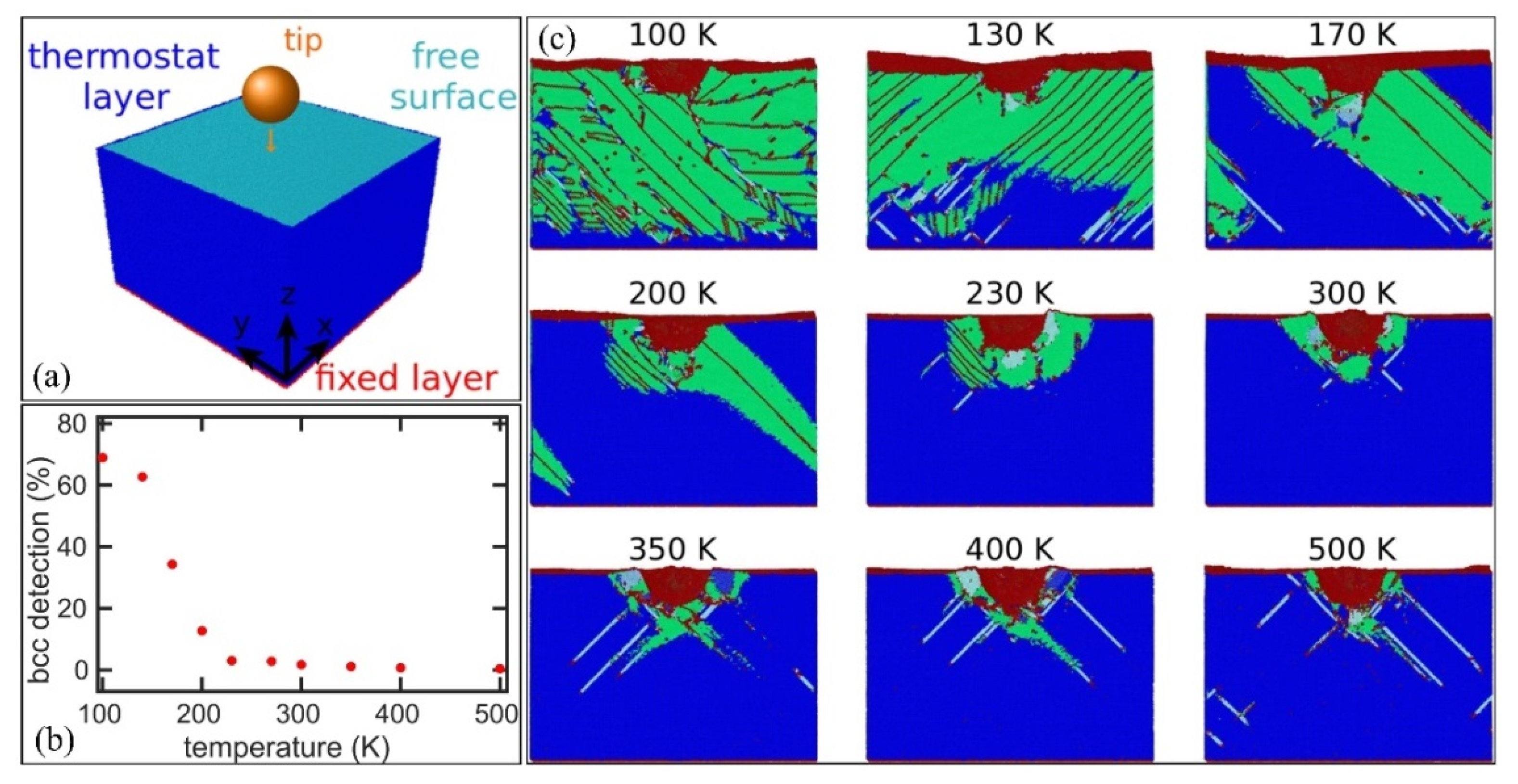
The nano-mechanical behavior of the austenite at different temperatures is investigated by the molecular dynamics (MD) simulation (Figure 8a,b) [113]. It is found that the martensitic transformation dominates over the whole austenite grain during nanoindentation investigation at a deformation temperature of 100 K (Figure 8c). The increase of deformation temperature reduces the amount of transformed martensite which is mainly confined to the area surrounding the indenter (Figure 8b,c). The remaining austenite is deformed by dislocation plasticity. No deformation twinning is observed for the warm-temperature deformation of austenite (500 K) (Figure 8c). Although the molecular dynamics investigation is effective to reveal the deformation behavior at different temperatures, the MD simulation involves a very high strain rate (20 m/s) [113], which cannot be achieved by the conventional loading rate of the nanoindentation test. Moreover, the austenite grain boundary is fixed, which limits transformation at the area close to the fixed boundary (Figure 8c).
The micro-pillar compression experiments can also be used to investigate the martensitic transformation in metastable retained austenite grains in AHSS. It is found that the martensitic transformation does not closely relate to the pop-ins during compression tests of nanoplate observed by in situ TEM [125]. The pop-in is explained instead through the generation of slip band and the geometrical softening of the nanoplate [125]. In contrast, most of the micro-pillar compression investigations suggest that the obvious strain burst is triggered by the formation of martensite [86,87,126]. The magnitude of strain burst is comparable to the calculated strain based on the estimation of the martensite area fraction normalized along the compression direction [126]. The discrepancy between these studies should be verified by further well-controlled experiments. For instance, the austenitic pillars with large diameters are desirable to avoid artifact such as buckling during the in situ compression test.
The nano-mechanical response of austenite during the micro-pillar compression test is different from that of the bulk counterpart. The martensite transformed in the micron-sized austenitic pillars in medium Mn steel (Fe-9Mn-0.6C in wt.%) has a lower dislocation density as compared to the martensite in bulk samples, which can be explained through the large surface-to-volume ratio of micro-pillar [126]. The shape strain of martensite transformed in a micro-pillar is well accommodated by the free surface without deforming the surrounding austenitic matrix and the martensite itself. The nucleation of martensite in the micron-pillar is at the intersected site of two stacking faults bundles [126]. It has been estimated that only a single nucleation site is pre-existed in bulk austenite with a grain size of 100 μm [127]. Therefore, the micron-pillar may lack the nucleation site of martensite owing to its small pillar size. Thus, the formation of the martensite nucleation site through the plastic deformation is a prerequisite for the commencement of martensitic transformation, i.e., intersected stacking faults [126].
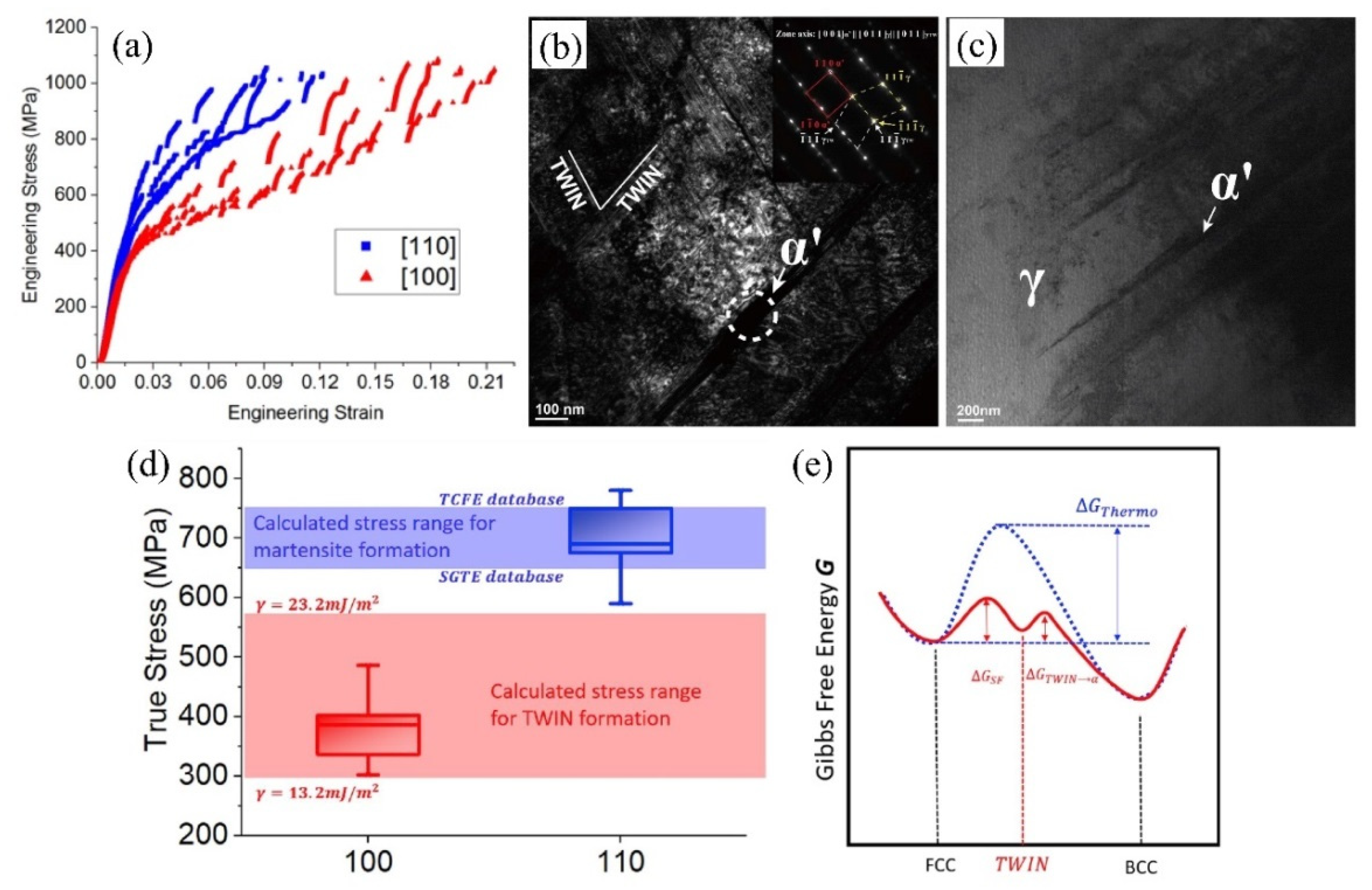
The martensitic transformation is found to be orientation-dependent during the compression test of the austenitic micro-pillars pillar in medium Mn steel (Fe-9Mn-0.6C in wt.%) [86,87]. The martensitic transformation can be identified in the austenitic micro-pillars with the orientation of [100] and [110]. Nevertheless, the [100] pillars demonstrate a far larger magnitude of strain burst than the [110] ones (Figure 9a), which can be ascribed to the much higher volume fraction of transformed martensite in [100] pillars considering the general correlation between the martensitic transformation and strain burst [86]. The [100] micro-pillars (~483 MPa) demonstrate a lower average critical stress as compared to that in [100] micro-pillars (~700 MPa) [87]. The deformation twins are observed in the deformed [110] micro-pillars but not in the deformed [100] micro-pillars (Figure 9b,c). The critical stress to initiate the deformation twins in the [100] micro-pillars is estimated to be around ~465 MPa, which is approaching the stress for generating martensite. Considering the similar theoretical stress for initiating the martensite in both micro-pillars (650–750 MPa), the reduced critical stress for triggering the martensitic transformation in [100] micro-pillars as compared to [100] micro-pillars could be ascribed to the twin-assisted nucleation of martensite at the intersections of two twin bundles (Figure 9d) [87]. Consequently, the orientation-dependent martensitic transformation observed during the micro-pillar compression test is ascribed to the different transformation pathways, including the twin-assisted and free-standing martensitic transformation (Figure 9e) [87].

3.3. Deformation Twins

The coherent twin boundaries are highly symmetric grain boundaries that can largely enhance the strength of metallic materials without sacrificing ductility [128,129]. However, the possibility for the operation of deformation twins in the austenite grains of CFB steel and the Q&P steel is generally low. This is because the formation of deformation twins requires low SFE (20–40 mJ/m−2) for the dissociation of perfect dislocations [85] and most of the austenite grains in CFB steel and Q&P steel does not have sufficient Mn and C content to satisfy the required SFE. However, the deformation twins can be occasionally found in the medium Mn steel with elevated Mn/C content [17,18,130,131]. In particular, the deformation twins in the high Mn steel such as TWIP steel are prevalent and are believed to be responsible for the high work hardening rate, which is generally known as the TWIP effect [132,133]. The formation of deformation twins enhances the work-hardening behavior by altering the dislocation structures [134]. The glissile dislocations in the matrix become sessile dislocations within the twin, accompanying with change of Burgers vector. For polycrystalline materials, the twin boundaries can serve as barriers to the dislocation slip, decreasing the dislocation mean free path and leading to the intensive interaction between dense dislocations and deformation twins [132,135,136]. Nevertheless, it is reported that the individual contribution of the deformation twins to the flow stress of TWIP steel is small as compared to the forest dislocation hardening, indicating the secondary role of deformation twins in TWIP steel [62]. Furthermore, it is argued that the interstitial atoms such as C atoms rather than the deformation twins play a crucial role in improving the work hardening of TWIP steel [137,138]. Note that the origin of enhanced work hardening behavior in TWIP steel with carbon atoms has already been discussed around 30 years ago [139]. The key to answering whether the TWIP effect is important for the TWIP steel is to reveal the exact resistance of single twin boundary to dislocation motions and the role of twinning arrangements on the strength.
The perfect dislocations in austenite grains with proper SFE (20–40 mJ/m−2) will be energetically favorable for dissociation into two partial dislocations, including leading partial dislocations and trailing partial dislocations. These two partial dislocations glide to different distances, connected by a ribbon known as the stacking fault, which is considered as a precursor for the generation of deformation twins [63,64]. Nevertheless, only the proper SFE is insufficient for deformation twins as they also depend on the crystal orientation. It is found that the deformation twins are favored in a single austenitic pillar with [001] orientation in a medium Mn steel (Fe-1.2C-7.0Mn in wt.%) under both nanoindentation and compression tests [81]. In contrast, only perfect dislocations are observed in the austenite grains with [111] orientation [81]. Therefore, the formation of mechanical twins is governed by the orientations which are closely related to the Schmid factor for twinning in fcc crystals [140,141].
The generation of deformation twins beneath the indenter is believed to be responsible for the observed large strain bursts during the nanoindentation test [81]. However, such belief has not been unambiguously verified. Considering the scenario that the simultaneous occurrence of the dislocation and deformation twins in a single indent while only one pop-in is detected in the P-h curve, it is a challenge to determine whether the yielding of single austenitic grain with a pop-in is induced by deformation twinning or dislocation glide [140]. Another possibility is that the plastic yielding of the [001] grain could be induced by both slip and twinning owing to their similar critical resolved shear stresses. However, this possibility has not been confirmed in a previous study [140].
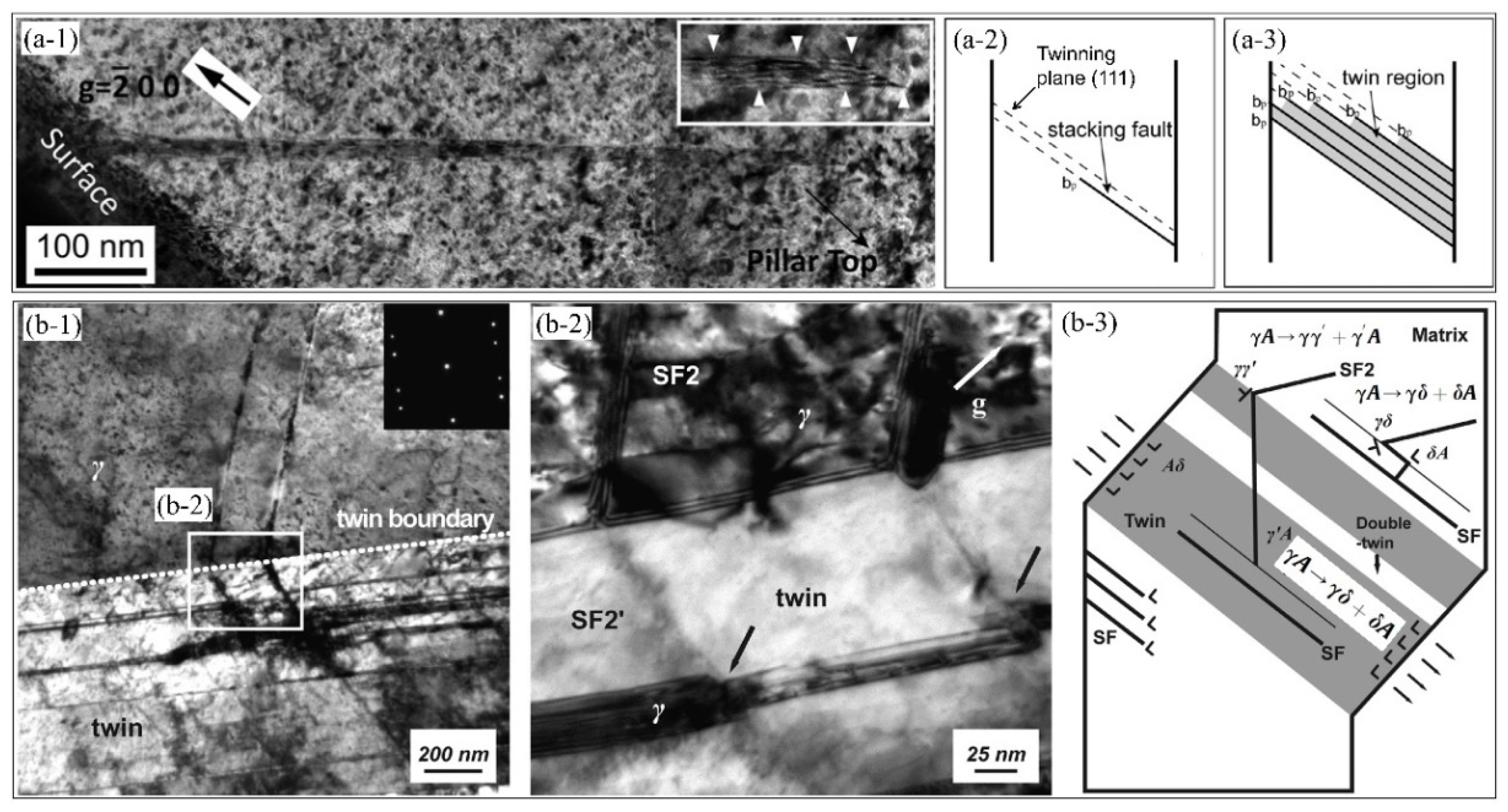
In addition to the nanoindentation test, the formation of deformation twins can also be investigated by a micro-pillar compression test with a typical flow curve as shown in Figure 10(a-1) [142]. The deformed micro-pillar is sheared along a single direction as depicted by SEM observation (Figure 10(a-2)). To reveal the underlying mechanism for such deformed morphology, the cross-section of the micro-pillar is fabricated by FIB and observed under TEM (Figure 10(a-3)). Interestingly, the deformed morphology coincides with the arrangement of the large deformation twins (Figure 10(a-2,a-3)), suggesting that the pillar morphology is induced by the generation of deformation twins. In addition to the large deformation twins with thickness of around 1 μm, profuse nanometer-sized deformation twins can also be observed in the micro-pillar compression test (Figure 10b) [142]. Nevertheless, a small number of twins with large thickness has also been observed in the micro-pillar compression test of TWIP steel in another study (Figure 10c) [70]. The formation of deformation twins with varied thickness may be due to the competition between the nucleation and growth processes of deformation twins.
The micron-pillar compression test of the single austenitic crystal shows that there is an obvious strain burst in the flow curve (Figure 10(a-3),c). The contribution of the deformation twins to the engineering strain can be estimated as below [70]:
ε t = T · γ t · cos ( α ) H
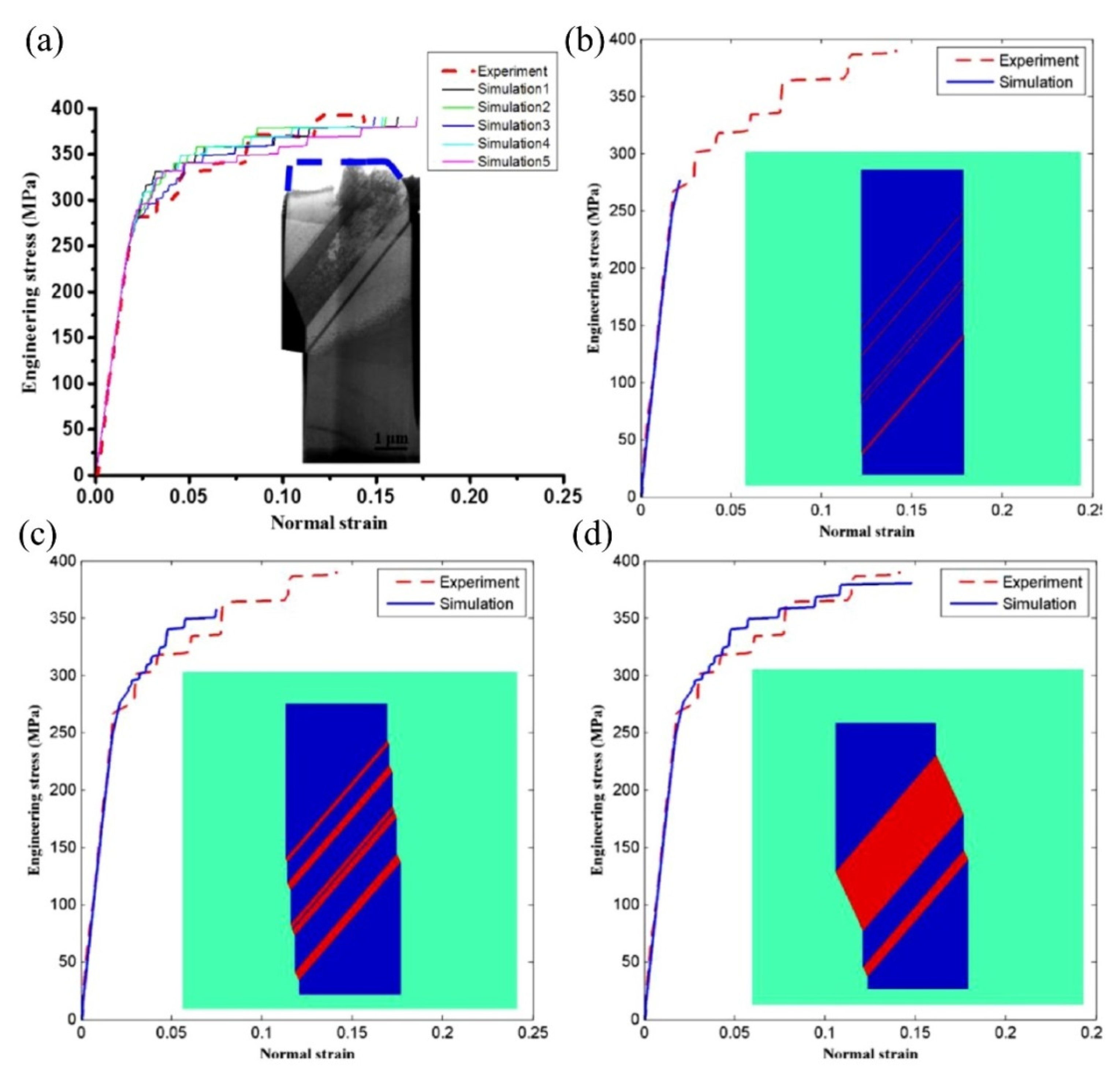
where εt is the strain induced by deformation twins, T is the overall thickness of deformation twins, γt is the strain sheared by deformation twinning which is 0.707 [143], and α is the deviation angle of active twinning direction from the pillar axis. H is the altitude of the micro-pillar before the compression test. The engineering strain estimated based on the above equation is similar to the observed strain burst in the engineering stress–strain curve, suggesting that the strain burst could be induced by the occurrence of deformation twins [70]. In particular, the deformation twins are carried out by the initiation of the layer-by-layer shearing because all partial dislocations for a twinning glide on the paralleled planes with the same Burgers vector [81]. This may be the fundamental reason for the occurrence of large strain bursts during the generation of deformation twins. A physically based model is developed by Liang and Huang [70], which takes the different sources and activation criteria of partial dislocations into consideration. This model captures the key feature of the flow curve including the twinning burst and also the twin evolution such as twin fraction and morphology, quantifying the contribution of the formation of deformation twins to the engineering strain (Figure 11) [70].
The nucleation of deformation twinning in austenitic micro-pillars during compression test is different from the bulk counterparts. There are different mechanisms for nucleation of deformation twinning during the compression test of austenitic micro-pillar in TWIP steel. The partial dislocations emitted from the pillar surface are found to be responsible for the growth of deformation twins (Figure 12a) [142]. In contrast, it is found that the interaction between dislocations is a prerequisite for generation of twin with the partial dislocations emitted from dislocation intersections (Figure 12b) [90]. Interestingly, the nucleation of twins could also be assisted by the defects created during the preparation of pillars at the ion-milling step [144]. The FIB techniques can induce damage to the pillar surface in terms of vacancy Frank loops induced by ion radiation. The dissociation of such loops beneath the surface may assist the nucleation of twins. The dissociation of dislocation into partial dislocations at the free surface provides the nucleation of twins. It is found that the pre-existing perfect dislocations within the pillar are also essential for the generation of deformation twins [144]. The growth of deformation twins in pillars can be ascribed to the glide of Shockley partial dislocations (SPDs) on successive consecutive {111} planes from the pillar surface [142].
The compression of micro-pillar in metallic materials with dominant dislocation plasticity demonstrates a size effect that is increased critical resolved shear stress with decreased diameter, which can be explained by the dislocation associated mechanisms such as dislocation starvation [145,146] and limited dislocation source size [147,148]. Nevertheless, the size effect can also be observed for the austenitic single crystal with the operation of the deformation twins, namely the stress for the twinning process increases with the decrease of pillar diameter (Figure 13) [144]. In particular, the yield stress (initiation of first strain burst) substantially increases with decreased pillar diameter ranging from 3 μm down to 0.5 μm (Figure 13), following a power-law relation with a smaller exponent (0.43) as compared to the one induced by dislocation activities (0.6–0.7) [144]. This is consistent with the nucleation mechanism of twinning from the surface dislocation emission. The deformation twins are found to be the dominant plastic mode in the pillars, suggesting that the size effect should be controlled by deformation twins on the aspect of twin nucleation and growth rather than by dislocation activity [144]. The preparation of the micro-pillar by FIB technique involves the ion bombardment which will induce a damaged layer incorporating the dislocation loops and other defects on the sample surface [149,150]. The dislocation loops induced by ion-radiation demonstrate a radius of several tens of nanometers, which can be activated at smaller stress as compared to the theoretical limit, suggesting that the introduction of dislocations by ion-radiation can alternatively serve as dislocation sources to compensate the limited pre-existing dislocation sources within the small sample volume for initiating plasticity [151]. The ion radiation can generate plastic deformation through point defects such as vacancy and embedded ions, inducing the local volume expansion, and producing the compressive residual stress state due to the mismatch between the irradiated and non-irradiated parts, which could help to dissociate the vacancy Frank loops for initiation of deformation twins [144]. The compressive stress induced by ion-radiation in the subsurface layer is found to decrease with an increase of pillar diameter, leading to the observed size effect for deformation twins during the compression test [144].
The effect of the twin boundaries on the strength of steel can be investigated by employing the pillar compression test. The twin boundaries are introduced and incorporated in the pillar with a diameter of 4 μm [90]. The pillar with twin boundaries demonstrates slightly larger and more jerky flow stresses than the pillar without twin boundaries, which is ascribed to the operation of secondary slip systems [90]. However, the comparison of the mechanical response between the small-volume single crystal and the polycrystalline bulk counterpart is inappropriate as the former plasticity is affected by the existence of free surfaces. The dislocations in the deformed micro-pillars can easily glide to the free surface with no storage of dense dislocations within the pillar, which is different from the mechanical behavior of the polycrystalline bulk material.
The plastic mode of the austenite including the pure dislocation plasticity and deformation twinning during the micro-pillar compression test depends on the crystal orientation [81]. It is found that the critical resolved shear stress of micro-pillars along different orientations favorable for either dislocation slip and deformation twins is similar (Figure 13) [90]. Based on this observation, it is further proposed that the initiation of plasticity in micro-pillars of TWIP steel is governed by the dislocation activity rather than by deformation twins, which is controversial with Liang’s work [144]. The formation of ε-martensite is observed in the deformed micro-pillars with deformation twins. Such ε-martensite is absent in bulk TWIP steel (Fe-22Mn-0.6C in wt.%) [90]. This observation may be explained if we consider the effect of ion damage with gallium implantation which is a ferrite stabilizer [100].
It is reported that the critical stress for initiation of deformation twins is higher than the one for perfect dislocation slip [74]. The plastic deformation of pillar oriented for deformation twins is initially carried out with generation and glide of leading partial dislocations. The partial dislocation transmits into twins and its emission from the intersected site of planar defects take place with the increase of plastic deformation, inducing the formation of double deformation twins [74]. The double-twin is the one that the stacking of the twin is rearranged into the original austenite matrix. The thin double-twins are observed within the thicker twins along with the primary slip system in the deformed micro-pillars. The dislocation interactions among the primary and conjugate slip systems can generate a sessile dislocation configuration known as the Lomer-Cottrell locks for inhibiting dislocation motion [152]. The nucleation of the deformation twin can be derived from the interaction between partial dislocations and Lomer-Cottrell locks [153]. In contrast, the planar dislocation glide is dominated in the micro-pillars with favorable orientation for dislocation plasticity. However, planar dislocation glide is mainly confined in the area close to the top part of along the primary slip plane, resulting in localized plastic deformation [74].

4. Concluding Remarks

Continuous efforts in understanding the nano/micro-mechanical behavior of austenite are beneficial for the alloy design, service behavior of small-volume materials in the industry such as MEMS, and the thorough capture of deformation mechanism of bulk materials. The nanoindentation measurement is a useful technique for extracting the bulk mechanical properties without destroying the specimen. The engineering stress–strain curves of individual constituting phases in AHSS can be extracted from the single small-scale test based on the nanoindentation test combined with microhardness measurements using the inverse method or by numerical methods and finite element analyses, which properly compare with the mechanical response obtained from the tensile tests [154,155]. The cyclic nanoindentation test has been employed to investigate the mechanical behavior of the austenitic stainless steel [156,157,158], demonstrating an interesting reverse transformation that does not exist in the macroscopic tensile test. However, such cyclic nanoindentation test has seldom been reported in the retained austenite grains in the AHSS, which requires further investigation. The nanohardness is calculated from the P-h curve by using the Oliver-Pharr method which relies on the precise detection of the indentation depth [73]. However, the nanohardness of austenite is strongly affected by the martensitic transformation. As has been discussed in Section 3.2, the metastable austenite grains during the nanoindentation test are heavily subjected to the martensitic transformation with the occurrence of strain burst which represents the geometrical softening, while the subsequent deformation of martensite contributes to the hardening of austenite [98,99]. The occurrence of the pop-in or the martensitic transformation makes the hardness closely dependent on the maximum depth, austenite stability, martensite size, and variants. The nano-mechanical behavior of metastable austenite grains in quenched and tempered steel with high carbon content exhibits double plastic deformation stages, including the initial martensite transformation followed by deformation of transformed martensite [119]. Therefore, it is quite challenging to decouple the contribution of transformed martensite to the calculation of nanohardness of the metastable austenite grains. In addition, the elastic deformation of the austenite during the unloading process is also affected by the formation of martensite, making the calculation of the intrinsic elastic modulus of austenite complex. One solution to obtain the inherent properties of the austenite grains is to inhibit the formation of martensite during the nanoindentation test [84]. It has been shown by MD simulation that the austenite grain can be stabilized by the high temperature in which the transformed volume of martensite is reduced [113]. It is reported that the nanoindentation test can be carried out at high temperatures with the reliable characterization of deformation behavior [159]. Therefore, it may be possible to obtain the nanohardness of the austenite at the different high temperatures without martensitic transformation and use these data to extrapolate to the nanohardness at room temperature. However, such nano-mechanical behavior of the austenite grains at high temperatures is less investigated in the open literature. Since the SFE of austenite grains increases with deformation temperature, the martensitic transformation may change to the deformation twinning, and then to the dominated dislocation plasticity encompassing the planar slip, cross-slip, and climb of dislocations.
The intrinsic austenite stability can be precisely revealed by the nanoindentation test. The formation of martensite is frequently accompanied by a strain burst after the initiation of dislocation plasticity. The load at which the second strain burst takes place is considered as the critical load for the formation of martensite and thus can be used to measure the stability of austenite. However, it is noted that such pop-in load for martensitic transformation is difficult to be used for comparison among different experiments. The pop-in stress is more useful than the pop-in load for comparison purposes. Such pop-in stress is difficult to be obtained owing to the complex stress field underneath the tip. Moreover, the nucleation of the martensite beneath the indenter is influenced by the interaction between the dislocations and the embryo of martensite at the austenite grain boundary. Such interaction depends on the indentation depth and the thickness of the indented austenite grains. The intrinsic stability of austenite grains is governed by the defect (dislocation) density, and chemical compositions (C/Mn), all of which can be investigated by nanoindentation test. It is noted that the austenite grains with filmy morphology are more stable than the blocky counterparts in Q&P steel during a tensile test, which is ascribed to the presence of hydrostatic pressure and higher defect density. In addition, the chemical compositions in the austenite grains with different morphologies could be different. Since there are different governing factors in affecting the austenite stability simultaneously, it is thus unclear whether the morphology of austenite can intrinsically affect the austenite stability, rather than coupling with other factors. It is known that the morphology of austenite grains in the rolled samples along the different observation directions is different. In other words, the granular morphology of austenite grains along the rolling direction may demonstrate the lamellar morphology along the transverse direction. By employing the nano-mechanical behavior of the austenite grains with different orientations, the statistical sense of the austenite stability with different morphology can be verified.
The tailored austenite stability beneficially enhances the work hardening behavior of AHSS containing the metastable austenite grains. The austenite grains with different mechanical stability can avoid either the scenario for the exhaustion of the austenite grains at the early deformation process or the remaining of the substantial amount of austenite after the necking process, both of which are undesirable for the enhancement of mechanical properties. The different austenite mechanical stability can be realized through tuning the governing factors such as the chemical compositions, grain size/morphology, and defect density. The MD simulation on the transformation behavior of the austenite during the indentation test suggests that the transformed amount of martensite largely depends on the deformation temperature [84]. Since the deformation temperature affects the austenite stability in a manner that can be equivalent to the chemical compositions, it is hypothesized that the single austenite grains with the varied chemical partitioning can be useful for the controlled release of TRIP effect, continuously improving the work hardening behaviors of AHSS. The chemical inhomogeneity such as Mn content has been proved to be effective for the development of high-performance medium Mn steel processed by splash heat treatment [5]. The Mn banding, which is generated during the solidification process, can also be used to tailor the austenite stability across a larger scale than the splash heat treatment [160].
In addition to the dislocation and martensitic transformation, the deformation twins are an important plasticity mode for the austenite grains with proper SFE in the AHSS. However, the impact of deformation twins on the work hardening of the TWIP steel is still under debate. The classic viewpoint on the deformation twins indicates that they play a critical role in enabling the high strength and good ductility of TWIP steel, which is typically referred to as the dynamic Hall-Petch effect by separating the austenite into smaller grains [132,133,135,136]. Nevertheless, the calculation of the overall dislocation density and the estimation of the contribution of dislocations to the flow stress by the classical Taylor hardening law suggest that the dislocations mostly contribute to the flow stress of TWIP steel [62]. Consequently, the newly developed viewpoint suggests that the interstitial carbon atoms rather than the deformation twins are critically important for the enhanced work hardening response of TWIP steel [137,138]. However, the presence of the deformation twins can also increase the dislocation density as they act as barriers for the dislocation slip. Therefore, the respective contribution from the deformation twins to the flow stress can be incorporated in the part contributed by the increased overall dislocation density. In other words, the contribution made by deformation twins to the flow stress is indirect through the increased dislocation density and it should be decoupled from the total increased dislocation density. The quantitative estimation of the single twin boundaries to the flow stress is important to identify if the engineering of such coherent twin boundary to the flow stress is effective. The resistance of the twin boundary to the dislocation glide should be weaker than the grain boundary [38]. From the aspect of alloy design, the ultimate question is about how to increase the deformation twin density and the optimization of the twin arrangement as well [161]. The contribution of the single twin boundaries to the flow stress has been estimated by using the small-scale test of a micro-pillar with a diameter of 4 μm [162]. However, it is difficult to correlate the results obtained from the small-scale test to the bulk mechanical behavior. For instance, the mechanical behavior of micro-pillar and nano-pillar during the compression test is largely affected by the presence of a free surface. This dilemma may be resolved by fabricating the pillar with relatively large diameter to capture the bulk mechanical behavior of TWIP steel. It has been shown that the size-dependent plasticity can be disregarded for pillar diameter larger than 7.6 μm based on a theoretical consideration of TWIP steel [90]. The proper comparison of the mechanical behavior of the large pillars with and without the deformation twins may be useful to verify the importance of the deformation twins to the strength of TWIP steel.

Author Contributions

Q.G.: Writing—Review & Editing. B.H.: Conception, Review & Editing, Funding acquisition. W.L.: Review & Editing, Funding acquisition. All authors have read and agreed to the published version of the manuscript.

Funding

This research was funded by National Natural Science Foundation of China [grant number U52071173], Science and Technology Innovation Commission of Shenzhen [grant number JCYJ20210324120209026, ZDSYS20200810171201007; KQTD2019092917250571], Start-up Funding from the Southern University of Science and Technology [grant number Y01336132, Y01336232]. The APC was funded by National Natural Science Foundation of China [grant number U52071173].

Institutional Review Board Statement

Not applicable.

Informed Consent Statement

Not applicable.

Data Availability Statement

No data, models, or code were generated or used during the study.

Conflicts of Interest

On behalf of all authors, the corresponding author states that there is no conflict of interest.

References

  1. Kuziak, R.; Kawalla, R.; Waengler, S. Advanced high strength steels for automotive industry. Arch. Civ. Mech. Eng. 2008, 8, 103–117. [Google Scholar] [CrossRef]
  2. Bouaziz, O.; Zurob, H.; Huang, M. Driving Force and Logic of Development of Advanced High Strength Steels for Automotive Applications. Steel Res. Int. 2013, 84, 937–947. [Google Scholar] [CrossRef]
  3. Owen, W.S. Can a simple heat treatment help to save Detroit? Metals Technol. 1980, 7, 1–13. [Google Scholar] [CrossRef]
  4. De Cooman, B.C.; Estrin, Y.; Kim, S.K. Twinning-induced plasticity (TWIP) steels. Acta. Mater. 2018, 142, 283–362. [Google Scholar] [CrossRef]
  5. Ding, R.; Yao, Y.; Sun, B.; Liu, G.; He, J.; Li, T.; Wan, X.; Dai, Z.; Ponge, D.; Raabe, D. Chemical boundary engineering: A new route toward lean, ultrastrong yet ductile steels. Sci. Adv. 2020, 6, 1430. [Google Scholar] [CrossRef] [Green Version]
  6. He, B.B.; Hu, B.; Yen, H.W.; Cheng, G.J.; Wang, Z.K.; Luo, H.W.; Huang, M.X. High dislocation density–induced large ductility in deformed and partitioned steels. Science 2017, 357, 1029–1032. [Google Scholar] [CrossRef] [PubMed] [Green Version]
  7. Caballero, F.G.; Bhadeshia, H.K.D.H. Very strong bainite. Curr. Opin. Solid State Mater. Sci. 2004, 8, 251–257. [Google Scholar] [CrossRef] [Green Version]
  8. Caballero, F.; Bhadeshia, H.; Mawella, K.; Jones, D.; Brown, P. Very strong low temperature bainite. Mater. Sci. Technol. 2002, 18, 279–284. [Google Scholar] [CrossRef] [Green Version]
  9. Shi, J.; Sun, X.J.; Wang, M.Q.; Hui, W.J.; Dong, H.; Cao, W.Q. Enhanced work-hardening behavior and mechanical properties in ultrafine-grained steels with large-fractioned metastable austenite. Scripta. Mater. 2010, 63, 815–818. [Google Scholar] [CrossRef]
  10. Lee, S.; Lee, S.J.; De Cooman, B.C. Austenite stability of ultrafine-grained transformation-induced plasticity steel with Mn partitioning. Scripta. Mater. 2011, 65, 225–228. [Google Scholar] [CrossRef]
  11. Niikura, M.; Morris, J. Thermal processing of ferritic 5Mn steel for toughness at cryogenic temperatures. MTA. 1980, 11, 1531–1540. [Google Scholar] [CrossRef]
  12. Speer, J.; Matlock, D.; De Cooman, B.; Schroth, J. Carbon partitioning into austenite after martensite transformation. Acta. Mater. 2003, 51, 2611–2622. [Google Scholar] [CrossRef]
  13. Wang, L.; Speer, J.G. Quenching and partitioning steel heat treatment. Metallogr. Microstruct. Anal. 2013, 2, 268–281. [Google Scholar] [CrossRef] [Green Version]
  14. Luo, H. Comments on “Austenite stability of ultrafine-grained transformation-induced plasticity steel with Mn partitioning” by S. Lee, S.J. Lee and B.C. De Cooman, Scripta Materialia 65 (2011) 225–228. Scripta Mater. 2012, 66, 829–831. [Google Scholar] [CrossRef]
  15. Lee, S.; Lee, S.-J.; De Cooman, B.C. Reply to comments on “Austenite stability of ultrafine-grained transformation-induced plasticity steel with Mn partitioning”. Scripta Mater. 2012, 66, 832–833. [Google Scholar] [CrossRef]
  16. He, B.B.; Huang, B.M.; He, S.H.; Qi, Y.; Yen, H.W.; Huang, M.X. Increasing yield strength of medium Mn steel by engineering multiple strengthening defects. Mater. Sci. Eng. A 2018, 724, 11–16. [Google Scholar] [CrossRef]
  17. Lee, S.; De Cooman, B.C. Tensile Behavior of Intercritically Annealed 10 pct Mn Multi-phase Steel. Metall. Mater. Trans. A 2014, 45, 709–716. [Google Scholar] [CrossRef] [Green Version]
  18. He, B.; Luo, H.; Huang, M. Experimental investigation on a novel medium Mn steel combining transformation-induced plasticity and twinning-induced plasticity effects. Int. J. Plast. 2016, 78, 173–186. [Google Scholar] [CrossRef]
  19. Mecking, H.; Kocks, U.F. Kinetics of flow and strain-hardening. Acta Metall. 1981, 29, 1865–1875. [Google Scholar] [CrossRef]
  20. Jacques, P.; Furnémont, Q.; Mertens, A.; Delannay, F. On the sources of work hardening in multiphase steels assisted by transformation-induced plasticity. Philos. Mag. A 2001, 81, 1789–1812. [Google Scholar] [CrossRef]
  21. Wang, M.M.; Tasan, C.C.; Ponge, D.; Dippel, A.C.; Raabe, D. Nanolaminate transformation-induced plasticity–twinning-induced plasticity steel with dynamic strain partitioning and enhanced damage resistance. Acta Mater. 2015, 85, 216–228. [Google Scholar] [CrossRef]
  22. Ashby, M.F. The deformation of plastically non-homogeneous materials. Philos. Mag. 1970, 21, 399–424. [Google Scholar] [CrossRef]
  23. He, B. On the Factors Governing Austenite Stability: Intrinsic versus Extrinsic. Materials 2020, 13, 3440. [Google Scholar] [CrossRef] [PubMed]
  24. Liu, L.; He, B.; Huang, M. The Role of Transformation-Induced Plasticity in the Development of Advanced High Strength Steels. Adv. Eng. Mater. 2018, 20, 1701083. [Google Scholar] [CrossRef]
  25. Furnémont, Q.; Kempf, M.; Jacques, P.J.; Göken, M.; Delannay, F. On the measurement of the nanohardness of the constitutive phases of TRIP-assisted multiphase steels. Mater. Sci. Eng. A 2002, 328, 26–32. [Google Scholar] [CrossRef]
  26. Morales-Rivas, L.; González-Orive, A.; Garcia-Mateo, C.; Hernández-Creus, A.; Caballero, F.G.; Vázquez, L. Nanomechanical characterization of nanostructured bainitic steel: Peak Force Microscopy and Nanoindentation with AFM. Sci. Rep. 2015, 5, 17164. [Google Scholar] [CrossRef] [PubMed] [Green Version]
  27. Lee, K.; Park, S.-J.; Choi, Y.S.; Kim, S.-J.; Lee, T.-H.; Oh, K.H.; Han, H.N. Dual-scale correlation of mechanical behavior in duplex low-density steel. Scripta Mater. 2013, 69, 618–621. [Google Scholar] [CrossRef]
  28. Seo, E.J.; Cho, L.; Kim, J.K.; Mola, J.; Zhao, L.; De Cooman, B.C. Constituent-specific properties in quenching and partitioning (Q&P) processed steel. Mater. Sci. Eng. A 2019, 740, 439–444. [Google Scholar]
  29. Park, H.S.; Han, J.C.; Lim, N.S.; Seol, J.-B.; Park, C.G. Nano-scale observation on the transformation behavior and mechanical stability of individual retained austenite in CMnSiAl TRIP steels. Mater. Sci. Eng. A 2015, 627, 262–269. [Google Scholar] [CrossRef]
  30. Mao, K.S.; Sun, C.; Shiau, C.-H.; Yano, K.H.; Freyer, P.D.; El-Azab, A.A.; Garner, F.A.; French, A.; Shao, L.; Wharry, J.P. Role of cavities on deformation-induced martensitic transformation pathways in a laser-welded, neutron irradiated austenitic stainless steel. Scripta Mater. 2020, 178, 1–6. [Google Scholar] [CrossRef]
  31. Roa, J.J.; Fargas, G.; Mateo, A.; Jiménez-Piqué, E. Dependence of nanoindentation hardness with crystallographic orientation of austenite grains in metastable stainless steels. Mater. Sci. Eng. A 2015, 645, 188–195. [Google Scholar] [CrossRef]
  32. Pan, S.; He, B. The respective strain hardening of constituting phases during Lüders deformation of a medium-Mn steel. Philos. Mag. Lett. 2021, 101, 211–221. [Google Scholar] [CrossRef]
  33. Greer, J.R.; De Hosson, J.T.M. Plasticity in small-sized metallic systems: Intrinsic versus extrinsic size effect. Prog. Mater. Sci. 2011, 56, 654–724. [Google Scholar] [CrossRef]
  34. Bouaziz, O.; Allain, S.; Scott, C.; Cugy, P.; Barbier, D. High manganese austenitic twinning induced plasticity steels: A review of the microstructure properties relationships. Curr. Opin. Solid State Mater. Sci. 2011, 15, 141–168. [Google Scholar] [CrossRef]
  35. Hu, B.; Luo, H.; Yang, F.; Dong, H. Recent progress in medium-Mn steels made with new designing strategies, a review. J. Mater. Sci. Technol. 2017, 33, 1457–1464. [Google Scholar] [CrossRef]
  36. Suh, D.-W.; Kim, S.-J. Medium Mn transformation-induced plasticity steels: Recent progress and challenges. Scripta Mater. 2017, 126, 63–67. [Google Scholar] [CrossRef]
  37. Yi, H.; Sun, L.; Xiong, X. Challenges in the formability of the next generation of automotive steel sheets. Mater. Sci. Technol. 2018, 34, 1112–1117. [Google Scholar] [CrossRef]
  38. Huang, M.; Liang, Z.; Luo, Z. Critical Assessment 15: Science of deformation and failure mechanisms in twinning induced plasticity steels. Mater. Sci. Technol. 2015, 31, 1265–1270. [Google Scholar] [CrossRef] [Green Version]
  39. Zhao, J.; Jiang, Z. Thermomechanical processing of advanced high strength steels. Prog. Mater. Sci. 2018, 94, 174–242. [Google Scholar] [CrossRef]
  40. Dai, Z.; Chen, H.; Ding, R.; Lu, Q.; Zhang, C.; Yang, Z.; van der Zwaag, S. Fundamentals and application of solid-state phase transformations for advanced high strength steels containing metastable retained austenite. Mater. Sci. Eng. R Rep. 2021, 143, 100590. [Google Scholar] [CrossRef]
  41. Tasan, C.C.; Diehl, M.; Yan, D.; Bechtold, M.; Roters, F.; Schemmann, L.; Zheng, C.; Peranio, N.; Ponge, D.; Koyama, M. An overview of dual-phase steels: Advances in microstructure-oriented processing and micromechanically guided design. Annu. Rev. Mater. Res. 2015, 45, 391–431. [Google Scholar] [CrossRef]
  42. Raabe, D.; Sun, B.; Da Silva, A.K.; Gault, B.; Yen, H.-W.; Sedighiani, K.; Sukumar, P.T.; Souza Filho, I.R.; Katnagallu, S.; Jägle, E. Current Challenges and Opportunities in Microstructure-Related Properties of Advanced High-Strength Steels. Metall. Mater. Trans. A 2020, 51, 5517–5586. [Google Scholar] [CrossRef]
  43. Uchic, M.D.; Dimiduk, D.M.; Florando, J.N.; Nix, W.D. Sample dimensions influence strength and crystal plasticity. Science 2004, 305, 986–989. [Google Scholar] [CrossRef]
  44. Xiong, X.C.; Chen, B.; Huang, M.X.; Wang, J.F.; Wang, L. The effect of morphology on the stability of retained austenite in a quenched and partitioned steel. Scripta Mater. 2013, 68, 321–324. [Google Scholar] [CrossRef]
  45. Bhadeshia, H.; Edmonds, D. The mechanism of bainite formation in steels. Acta Metall. 1980, 28, 1265–1273. [Google Scholar] [CrossRef]
  46. Greenwood, G.W.; Johnson, R.H. The Deformation of Metals Under Small Stresses During Phase Transformations. Proc. R. Soc. Lond. A 1965, 283, 403–422. [Google Scholar]
  47. He, B.B.; Wang, M.; Huang, M.X. Improving Tensile Properties of Room-Temperature Quenching and Partitioning Steel by Dislocation Engineering. Metall. Mater. Trans. A 2019, 50, 4021–4026. [Google Scholar] [CrossRef]
  48. Han, J.; Lee, S.-J.; Jung, J.-G.; Lee, Y.-K. The effects of the initial martensite microstructure on the microstructure and tensile properties of intercritically annealed Fe–9Mn–0.05 C steel. Acta Mater. 2014, 78, 369–377. [Google Scholar] [CrossRef]
  49. Han, Q.; Zhang, Y.; Wang, L. Effect of annealing time on microstructural evolution and deformation characteristics in 10Mn1. 5Al TRIP steel. Metall. Mater. Trans. A 2015, 46, 1917–1926. [Google Scholar] [CrossRef]
  50. Chbihi, A.; Barbier, D.; Germain, L.; Hazotte, A.; Gouné, M. Interactions between ferrite recrystallization and austenite formation in high-strength steels. J. Mater. Sci. 2014, 49, 3608–3621. [Google Scholar] [CrossRef]
  51. Lawrynowicz, Z. Carbon partitioning during bainite transformation in low alloy steels. Mater. Sci. Technol. 2002, 18, 1322–1324. [Google Scholar] [CrossRef]
  52. Bracke, L.; Verbeken, K.; Kestens, L.; Penning, J. Microstructure and texture evolution during cold rolling and annealing of a high Mn TWIP steel. Acta Mater. 2009, 57, 1512–1524. [Google Scholar] [CrossRef]
  53. Haase, C.; Ingendahl, T.; Güvenç, O.; Bambach, M.; Bleck, W.; Molodov, D.A.; Barrales-Mora, L.A. On the applicability of recovery-annealed twinning-induced plasticity steels: Potential and limitations. Mater. Sci. Eng. A 2016, 649, 74–84. [Google Scholar] [CrossRef]
  54. Xiong, T.; Zheng, S.; Zhou, Y.; Pang, J.; Jin, Q.; Ge, H.; Zheng, X.; Yang, L.; Beyerlein, I.; Ma, X. Enhancing strength and thermal stability of TWIP steels with a heterogeneous structure. Mater. Sci. Eng. A 2018, 720, 231–237. [Google Scholar] [CrossRef]
  55. Zhou, P.; Liang, Z.Y.; Liu, R.D.; Huang, M.X. Evolution of dislocations and twins in a strong and ductile nanotwinned steel. Acta Mater. 2016, 111, 96–107. [Google Scholar] [CrossRef]
  56. Liu, L.; He, B.; Cheng, G.; Yen, H.; Huang, M. Optimum properties of quenching and partitioning steels achieved by balancing fraction and stability of retained austenite. Scripta Mater. 2018, 150, 1–6. [Google Scholar] [CrossRef]
  57. Gong, W.; Tomota, Y.; Harjo, S.; Su, Y.H.; Aizawa, K. Effect of prior martensite on bainite transformation in nanobainite steel. Acta Mater. 2015, 85, 243–249. [Google Scholar] [CrossRef]
  58. Beladi, H.; Tari, V.; Timokhina, I.B.; Cizek, P.; Rohrer, G.S.; Rollett, A.D.; Hodgson, P.D. On the crystallographic characteristics of nanobainitic steel. Acta Mater. 2017, 127, 426–437. [Google Scholar] [CrossRef] [Green Version]
  59. Wang, X.; He, B.; Liu, C.; Jiang, C.; Huang, M. Extraordinary Lüders-strain-rate in medium Mn steels. Materialia 2019, 6, 100288. [Google Scholar] [CrossRef]
  60. Liang, Z.Y.; Cao, Z.H.; Lu, J.; Huang, M.X.; Tasan, C.C. Influence of co-existing medium Mn and dual phase steel microstructures on ductility and Lüders band formation. Acta Mater. 2021, 117418. [Google Scholar] [CrossRef]
  61. Liang, Z.; Wang, X.; Huang, W.; Huang, M. Strain rate sensitivity and evolution of dislocations and twins in a twinning-induced plasticity steel. Acta Mater. 2015, 88, 170–179. [Google Scholar] [CrossRef]
  62. Liang, Z.Y.; Li, Y.Z.; Huang, M.X. The respective hardening contributions of dislocations and twins to the flow stress of a twinning-induced plasticity steel. Scripta Mater. 2016, 112, 28–31. [Google Scholar] [CrossRef]
  63. Mahajan, S.; Chin, G. Formation of deformation twins in fcc crystals. Acta Metall. 1973, 21, 1353–1363. [Google Scholar] [CrossRef]
  64. Hung, C.-Y.; Bai, Y.; Shimokawa, T.; Tsuji, N.; Murayama, M. A correlation between grain boundary character and deformation twin nucleation mechanism in coarse-grained high-Mn austenitic steel. Sci. Rep. 2021, 11, 8468. [Google Scholar] [CrossRef]
  65. Allain, S.; Chateau, J.P.; Bouaziz, O.; Migot, S.; Guelton, N. Correlations between the calculated stacking fault energy and the plasticity mechanisms in Fe–Mn–C alloys. Mater. Sci. Eng. A 2004, 387, 158–162. [Google Scholar] [CrossRef]
  66. Dumay, A.; Chateau, J.-P.; Allain, S.; Migot, S.; Bouaziz, O. Influence of addition elements on the stacking-fault energy and mechanical properties of an austenitic Fe–Mn–C steel. Mater. Sci. Eng. A 2008, 483, 184–187. [Google Scholar] [CrossRef]
  67. Saeed-Akbari, A.; Imlau, J.; Prahl, U.; Bleck, W. Derivation and Variation in Composition-Dependent Stacking Fault Energy Maps Based on Subregular Solution Model in High-Manganese Steels. Metall. Mater. Trans. A 2009, 40, 3076–3090. [Google Scholar] [CrossRef]
  68. Curtze, S.; Kuokkala, V.-T. Dependence of tensile deformation behavior of TWIP steels on stacking fault energy, temperature and strain rate. Acta Mater. 2010, 58, 5129–5141. [Google Scholar] [CrossRef]
  69. Olson, G.; Cohen, M. A general mechanism of martensitic nucleation: Part II. FCC → BCC and other martensitic transformations. Metall. Mater. Trans. A 1976, 7, 1905–1914. [Google Scholar]
  70. Liang, Z.; Huang, M. Deformation twinning in small-sized face-centred cubic single crystals: Experiments and modelling. J. Mech. Phys. Solids 2015, 85, 128–142. [Google Scholar] [CrossRef]
  71. Johnson, K.L. Contact Mechanics; Cambridge University Press: Cambridge, UK, 1985. [Google Scholar]
  72. Chiu, Y.L.; Ngan, A.H.W. A TEM investigation on indentation plastic zones in Ni3Al(Cr,B) single crystals. Acta Mater. 2002, 50, 2677–2691. [Google Scholar] [CrossRef]
  73. Oliver, W.C.; Pharr, G.M. Improved technique for determining hardness and elastic modulus using load and displacement sensing indentation experiments. J. Mater. Res. 1992, 7, 1564–1583. [Google Scholar] [CrossRef]
  74. Choi, W.S.; Sandlöbes, S.; Malyar, N.V.; Kirchlechner, C.; Korte-Kerzel, S.; Dehm, G.; De Cooman, B.C.; Raabe, D. Dislocation interaction and twinning-induced plasticity in face-centered cubic Fe-Mn-C micro-pillars. Acta Mater. 2017, 132, 162–173. [Google Scholar] [CrossRef]
  75. Honeycombe, R. The Plastic Deformation of Metals; Edward Arnold Ltd.: London, UK, 1984. [Google Scholar]
  76. Soer, W.A.; Aifantis, K.E.; De Hosson, J.T.M. Incipient plasticity during nanoindentation at grain boundaries in body-centered cubic metals. Acta Mater. 2005, 53, 4665–4676. [Google Scholar] [CrossRef] [Green Version]
  77. Durst, K.; Backes, B.; Franke, O.; Göken, M. Indentation size effect in metallic materials: Modeling strength from pop-in to macroscopic hardness using geometrically necessary dislocations. Acta Mater. 2006, 54, 2547–2555. [Google Scholar] [CrossRef]
  78. Durst, K.; Franke, O.; Böhner, A.; Göken, M. Indentation size effect in Ni–Fe solid solutions. Acta Materialia 2007, 55, 6825–6833. [Google Scholar] [CrossRef]
  79. Nix, W.D.; Gao, H. Indentation size effects in crystalline materials: A law for strain gradient plasticity. J. Mech. Phys. Solids 1998, 46, 411–425. [Google Scholar] [CrossRef]
  80. Ohmura, T.; Minor, A.; Stach, E.; Morris, J. Dislocation–grain boundary interactions in martensitic steel observed through in situ nanoindentation in a transmission electron microscope. J. Mater. Res. 2004, 19, 3626–3632. [Google Scholar] [CrossRef]
  81. Seo, E.J.; Kim, J.K.; Cho, L.; Mola, J.; Oh, C.Y.; De Cooman, B.C. Micro-plasticity of medium Mn austenitic steel: Perfect dislocation plasticity and deformation twinning. Acta Mater. 2017, 135, 112–123. [Google Scholar] [CrossRef]
  82. Kurdjumov, G.V.; Sachs, G. Over the mechanisms of steel hardening. Z. Physik 1930, 64, 325–343. [Google Scholar]
  83. Wassermann, G.; Mitt, K. About the mechanism of α–γ transformation of the iron. Wilh. Inst. Eisenforsch 1935, 17, 149. [Google Scholar]
  84. He, B.; Pan, S. Revealing the intrinsic nanohardness of retained austenite grain in a medium Mn steel with heterogeneous structure. Mater. Charact. 2021, 171, 110745. [Google Scholar] [CrossRef]
  85. Allain, S.; Chateau, J.P.; Bouaziz, O. A physical model of the twinning-induced plasticity effect in a high manganese austenitic steel. Mater. Sci. Eng. A 2004, 387, 143–147. [Google Scholar] [CrossRef]
  86. Nimaga, O.; Cheng, G.; Yen, H.; Huang, M. Large strain burst induced by martensitic transformation in austenitic micropillars. Scripta Mater. 2017, 137, 64–68. [Google Scholar] [CrossRef]
  87. Nimaga, O.; He, B.; Cheng, G.; Yen, H.; Huang, M. Revealing orientation-dependent martensitic transformation in a medium Mn steel by micropillar compression. Int. J. Plast. 2019, 123, 165–177. [Google Scholar] [CrossRef]
  88. Csikor, F.F.; Motz, C.; Weygand, D.; Zaiser, M.; Zapperi, S. Dislocation avalanches, strain bursts, and the problem of plastic forming at the micrometer scale. Science 2007, 318, 251–254. [Google Scholar] [CrossRef] [PubMed] [Green Version]
  89. Kirchlechner, C.; Keckes, J.; Motz, C.; Grosinger, W.; Kapp, M.W.; Micha, J.-S.; Ulrich, O.; Dehm, G. Impact of instrumental constraints and imperfections on the dislocation structure in micron-sized Cu compression pillars. Acta Mater. 2011, 59, 5618–5626. [Google Scholar] [CrossRef]
  90. Choi, W.S.; De Cooman, B.C.; Sandlöbes, S.; Raabe, D. Size and orientation effects in partial dislocation-mediated deformation of twinning-induced plasticity steel micro-pillars. Acta Mater. 2015, 98, 391–404. [Google Scholar] [CrossRef]
  91. Ryu, J.H.; Kim, D.-I.; Kim, H.S.; Bhadeshia, H.K.D.H.; Suh, D.-W. Strain partitioning and mechanical stability of retained austenite. Scripta Mater. 2010, 63, 297–299. [Google Scholar] [CrossRef]
  92. Olson, G.; Cohen, M. A general mechanism of martensitic nucleation: Part I. General concepts and the FCC → HCP transformation. Metall. Mater. Trans. A 1976, 7, 1897–1904. [Google Scholar]
  93. Lehnert, R.; Weidner, A.; Motylenko, M.; Biermann, H. Strain hardening of phases in high-alloy CrMnNi steel as a consequence of pre-deformation studied by nanoindentation. Adv. Eng. Mater. 2019, 21, 1800801. [Google Scholar] [CrossRef]
  94. Kim, Y.; Ahn, T.-H.; Suh, D.-W.; Han, H.N. Variant selection during mechanically induced martensitic transformation of metastable austenite by nanoindentation. Scripta Mater. 2015, 104, 13–16. [Google Scholar] [CrossRef]
  95. He, B.B.; Shang, X.K. Stress-induced martensitic transformation in metastable austenite grains during nanoindentation investigation. Philos. Mag. Lett. 2021, 101, 1–15. [Google Scholar] [CrossRef]
  96. He, B.; Pan, S. Correlation between Martensitic Transformation and Strain Burst in Retained Austenite Grains During Nanoindentation Investigation. Met. Mater. Int. 2021, 16, 1–6. [Google Scholar] [CrossRef]
  97. Zeisig, J.; Hufenbach, J.; Wendrock, H.; Gemming, T.; Eckert, J.; Kühn, U. A study of the micro-and nanoscale deformation behavior of individual austenitic dendrites in a FeCrMoVC cast alloy using micro-and nanoindentation experiments. Appl. Phys. Lett. 2016, 108, 143103. [Google Scholar] [CrossRef]
  98. He, B.B.; Huang, M.X.; Liang, Z.Y.; Ngan, A.H.W.; Luo, H.W.; Shi, J.; Cao, W.Q.; Dong, H. Nanoindentation investigation on the mechanical stability of individual austenite grains in a medium-Mn transformation-induced plasticity steel. Scripta Mater. 2013, 69, 215–218. [Google Scholar] [CrossRef]
  99. Ahn, T.H.; Oh, C.S.; Kim, D.H.; Oh, K.H.; Bei, H.; George, E.P.; Han, H.N. Investigation of strain-induced martensitic transformation in metastable austenite using nanoindentation. Scripta Mater. 2010, 63, 540–543. [Google Scholar] [CrossRef]
  100. Babu, R.P.; Irukuvarghula, S.; Harte, A.; Preuss, M. Nature of gallium focused ion beam induced phase transformation in 316L austenitic stainless steel. Acta Mater. 2016, 120, 391–402. [Google Scholar] [CrossRef]
  101. Knipling, K.; Rowenhorst, D.; Fonda, R.; Spanos, G. Effects of focused ion beam milling on austenite stability in ferrous alloys. Mater. Charact. 2010, 61, 1–6. [Google Scholar] [CrossRef]
  102. He, B.B.; Huang, M.X.; Ngan, A.H.W.; Van Der Zwaag, S. Effect of Free Surface on the Stability of Individual Retained Austenite Grains in a Duplex Stainless Steel. Metall. Mater. Trans. A 2014, 45, 4875–4881. [Google Scholar] [CrossRef]
  103. Gadelrab, K.R.; Li, G.; Chiesa, M.; Souier, T. Local characterization of austenite and ferrite phases in duplex stainless steel using MFM and nanoindentation. J. Mater. Res. 2012, 27, 1573. [Google Scholar] [CrossRef] [Green Version]
  104. Sort, J.; Concustell, A.; Menéndez, E.; Suriñach, S.; Baró, M.; Farran, J.; Nogués, J. Selective generation of local ferromagnetism in austenitic stainless steel using nanoindentation. Appl. Phys. Lett. 2006, 89, 032509. [Google Scholar] [CrossRef] [Green Version]
  105. Lu, X.; Ma, Y.; Zamanzade, M.; Deng, Y.; Wang, D.; Bleck, W.; Song, W.; Barnoush, A. Insight into hydrogen effect on a duplex medium-Mn steel revealed by in-situ nanoindentation test. Int. J. Hydrog. Energy 2019, 44, 20545–20551. [Google Scholar] [CrossRef]
  106. Pöhl, F. Local deformation and transformation behavior of retained austenite in 18CrNiMo7-6 after high-carbon carburizing treatment. Mater. Charact. 2020, 167, 110446. [Google Scholar] [CrossRef]
  107. Fischer-Cripps, A.C.; Nicholson, D. Nanoindentation. Mechanical engineering series. Appl. Mech. Rev. 2004, 57, B12. [Google Scholar] [CrossRef]
  108. Bhadeshia, H.K.D.H.; Honeycombe, R. Steels: Microstructure and Properties, 3rd ed.; Butterworth-Heinemann: Oxford, UK, 2006. [Google Scholar]
  109. Patel, J.R.; Cohen, M. Criterion for the action of applied stress in the martensitic transformation. Acta Metall. 1953, 1, 531–538. [Google Scholar] [CrossRef]
  110. Meng, Q.; Rong, Y.; Hsu, T. Effect of internal stress on autocatalytic nucleation of martensitic transformation. Metall. Mater. Trans. A 2006, 37, 1405–1411. [Google Scholar] [CrossRef]
  111. Wechsler, M.S. On the theory of the formation of martensite. Trans. Aime. 1953, 197, 1503–1515. [Google Scholar]
  112. Takashima, K.; Higo, Y.; Nunomura, S. The propagation velocity of the martensitic transformation in 304 stainless steel. Philos. Mag. A 1984, 49, 231–241. [Google Scholar] [CrossRef]
  113. Meiser, J.; Alhafez, I.A.; Beck, T.; Smaga, M.; Müller, R.; Urbassek, H.M. Nanoindentation into a metastable austenite triggers the martensitic phase transformation—An atomistic study. AIP Adv. 2019, 9, 015228. [Google Scholar] [CrossRef] [Green Version]
  114. Hossain, R.; Pahlevani, F.; Sahajwalla, V. Stability of retained austenite in high carbon steel–Effect of post-tempering heat treatment. Mater. Charact. 2019, 149, 239–247. [Google Scholar] [CrossRef]
  115. Lu, X.; Li, W.; Zhao, H.; Jin, X. Local plastic indentation resistance of retained austenite in bearing steel. ISIJ Int. 2016, 56, 851–854, ISIJINT-2015-480. [Google Scholar]
  116. He, B.B.; Huang, M.X. Revealing heterogeneous C partitioning in a medium Mn steel by nanoindentation. Mater. Sci. Technol. 2017, 33, 552–558. [Google Scholar] [CrossRef]
  117. Sabooni, S.; Aghaei, Z.; Karimzadeh, F.; Enayati, M.H.; Ngan, A.H.W. Austenite Stability during Nanoindentation of Ultrafine and Coarse Grained AISI 304L Stainless Steels. Int. J. Iron Steel Soc. Iran 2014, 11, 1–5. [Google Scholar]
  118. Sadeghpour, S.; Kermanpur, A.; Najafizadeh, A. Investigation of the effect of grain size on the strain-induced martensitic transformation in a high-Mn stainless steel using nanoindentation. Mater. Sci. Eng. A 2014, 612, 214–216. [Google Scholar] [CrossRef]
  119. Man, T.; Ohmura, T.; Tomota, Y. Mechanical behavior of individual retained austenite grains in high carbon quenched-tempered steel. ISIJ Int. 2019, 59, 559–566. [Google Scholar] [CrossRef] [Green Version]
  120. Misra, R.; Zhang, Z.; Jia, Z.; Somani, M.; Karjalainen, L. Probing deformation processes in near-defect free volume in high strength–high ductility nanograined/ultrafine-grained (NG/UFG) metastable austenitic stainless steels. Scripta Mater. 2010, 63, 1057–1060. [Google Scholar] [CrossRef]
  121. Olson, G.; Cohen, M. A mechanism for the strain-induced nucleation of martensitic transformations. J. Less Common Met. 1972, 28, 107–118. [Google Scholar] [CrossRef]
  122. Olson, G.; Cohen, M. Kinetics of strain-induced martensitic nucleation. Metall. Mater. Trans. A 1975, 6, 791–795. [Google Scholar] [CrossRef]
  123. Taboada, M.; Elizalde, M.; Jorge-Badiola, D. Austempering in low-C steels: Microstructure development and nanohardness characterization. J. Mater. Sci. 2019, 54, 5044–5060. [Google Scholar] [CrossRef]
  124. Weidner, A.; Hangen, U.D.; Biermann, H. Nanoindentation measurements on deformation-induced α’-martensite in a metastable austenitic high-alloy CrMnNi steel. Philos. Mag. Lett. 2014, 94, 522. [Google Scholar] [CrossRef]
  125. Kim, Y.-J.; Yoo, B.-G.; Choi, I.-C.; Seok, M.-Y.; Kim, J.-Y.; Ohmura, T.; Jang, J.-i. Martensitic phase transformation and pop-in in compression of austenitic steel nanoplates observed in situ by transmission electron microscopy. Mater. Lett. 2012, 75, 107–110. [Google Scholar] [CrossRef]
  126. Wu, S.; Liang, Z.; He, B.; Huang, M. Martensitic Transformation in Micron-Sized Fcc Single Crystals. Metall. Mater. Trans. A 2014, 45, 4731–4736. [Google Scholar] [CrossRef]
  127. Olson, G.B.; Cohen, M. A Perspective on Martensitic Nucleation. Annu. Rev. Mater. Sci. 1981, 11, 1–32. [Google Scholar] [CrossRef]
  128. Lu, K.; Lu, L.; Suresh, S. Strengthening materials by engineering coherent internal boundaries at the nanoscale. Science 2009, 324, 349–352. [Google Scholar] [CrossRef] [PubMed] [Green Version]
  129. Lu, L.; Shen, Y.; Chen, X.; Qian, L.; Lu, K. Ultrahigh strength and high electrical conductivity in copper. Science 2004, 304, 422–426. [Google Scholar] [CrossRef] [Green Version]
  130. Lee, S.; De Cooman, B.C. Influence of Intra-granular Ferrite on the Tensile Behavior of Intercritically Annealed 12 pct Mn TWIP+ TRIP Steel. Metall. Mater. Trans. A 2015, 46, 1012–1018. [Google Scholar] [CrossRef]
  131. Lee, S.; Lee, K.; De Cooman, B.C. Observation of the TWIP+ TRIP Plasticity-Enhancement Mechanism in Al-Added 6 Wt Pct Medium Mn Steel. Metall. Mater. Trans. A 2015, 46, 2356–2363. [Google Scholar] [CrossRef]
  132. Bouaziz, O.; Guelton, N. Modelling of TWIP effect on work-hardening. Mater. Sci. Eng. A 2001, 319, 246–249. [Google Scholar] [CrossRef]
  133. Bouaziz, O. Strain-hardening of twinning-induced plasticity steels. Scripta Mater. 2012, 66, 982–985. [Google Scholar] [CrossRef]
  134. Kalidindi, S.R.; Salem, A.A.; Doherty, R.D. Role of deformation twinning on strain hardening in cubic and hexagonal polycrystalline metals. Adv. Eng. Mater. 2003, 5, 229–232. [Google Scholar] [CrossRef]
  135. Gutierrez-Urrutia, I.; Raabe, D. Dislocation and twin substructure evolution during strain hardening of an Fe–22wt.% Mn–0.6 wt.% C TWIP steel observed by electron channeling contrast imaging. Acta Mater. 2011, 59, 6449–6462. [Google Scholar] [CrossRef]
  136. Steinmetz, D.R.; Jäpel, T.; Wietbrock, B.; Eisenlohr, P.; Gutierrez-Urrutia, I.; Saeed–Akbari, A.; Hickel, T.; Roters, F.; Raabe, D. Revealing the strain-hardening behavior of twinning-induced plasticity steels: Theory, simulations, experiments. Acta Mater. 2013, 61, 494–510. [Google Scholar] [CrossRef]
  137. Luo, Z.C.; Huang, M.X. The role of interstitial carbon atoms on the strain-hardening rate of twinning-induced plasticity steels. Scripta Mater. 2020, 178, 264–268. [Google Scholar] [CrossRef]
  138. Luo, Z.C.; Huang, M.X. Revisit the role of deformation twins on the work-hardening behaviour of twinning-induced plasticity steels. Scripta Mater. 2018, 142, 28–31. [Google Scholar] [CrossRef]
  139. Chou, J.-S.; Chao, C.-G. Effects of carbon contents on the tensile properties and deformed microstructures of austentitic Fe-28Mn-9Al-XC alloys. Scripta Metall. Mater. 1992, 27, 1229–1234. [Google Scholar] [CrossRef]
  140. Kang, S.; Jung, Y.-S.; Yoo, B.-G.; Jang, J.-i.; Lee, Y.-K. Orientation-dependent indentation modulus and yielding in a high Mn twinning-induced plasticity steel. Mater. Sci. Eng. A 2012, 532, 500–504. [Google Scholar] [CrossRef]
  141. Liang, Z.; Huang, M. Effects of Crystal Orientation on Deformation Twinning and Dislocation Slip in Single Crystal Micro-pillars of a Twinning-Induced Plasticity Steel. Metall. Mater. Trans. A 2021, 1–8. [Google Scholar] [CrossRef]
  142. Wu, S.Z.; Yen, H.W.; Huang, M.X.; Ngan, A.H.W. Deformation twinning in submicron and micron pillars of twinning-induced plasticity steel. Scripta Mater. 2012, 67, 641–644. [Google Scholar] [CrossRef]
  143. Christian, J.W.; Mahajan, S. Deformation twinning. Prog. Mater. Sci. 1995, 39, 1–157. [Google Scholar] [CrossRef]
  144. Liang, Z.Y.; De Hosson, J.T.M.; Huang, M.X. Size effect on deformation twinning in face-centred cubic single crystals: Experiments and modelling. Acta Mater. 2017, 129, 1–10. [Google Scholar] [CrossRef] [Green Version]
  145. Greer, J.R.; Oliver, W.C.; Nix, W.D. Size dependence of mechanical properties of gold at the micron scale in the absence of strain gradients. Acta Mater. 2005, 53, 1821–1830. [Google Scholar] [CrossRef]
  146. Greer, J.R.; Nix, W.D. Nanoscale gold pillars strengthened through dislocation starvation. Phys. Rev. B 2006, 73, 245410. [Google Scholar] [CrossRef] [Green Version]
  147. Parthasarathy, T.A.; Rao, S.I.; Dimiduk, D.M.; Uchic, M.D.; Trinkle, D.R. Contribution to size effect of yield strength from the stochastics of dislocation source lengths in finite samples. Scripta Mater. 2007, 56, 313–316. [Google Scholar] [CrossRef]
  148. Volkert, C.A.; Lilleodden, E.T. Size effects in the deformation of sub-micron Au columns. Philos. Mag. 2006, 86, 5567–5579. [Google Scholar] [CrossRef]
  149. Kiener, D.; Zhang, Z.; Šturm, S.; Cazottes, S.; Imrich, P.J.; Kirchlechner, C.; Dehm, G. Advanced nanomechanics in the TEM: Effects of thermal annealing on FIB prepared Cu samples. Philos. Mag. 2012, 92, 3269–3289. [Google Scholar] [CrossRef]
  150. Marien, J.; Plitzko, J.; Spolenak, R.; Keller, R.; Mayer, J. Quantitative electron spectroscopic imaging studies of microelectronic metallization layers. J. Microsc. 1999, 194, 71–78. [Google Scholar] [CrossRef]
  151. Lee, S.; Jeong, J.; Kim, Y.; Han, S.M.; Kiener, D.; Oh, S.H. FIB-induced dislocations in Al submicron pillars: Annihilation by thermal annealing and effects on deformation behavior. Acta Mater. 2016, 110, 283–294. [Google Scholar] [CrossRef]
  152. Karnthaler, H.P.; Wintner, E. Weak beam Tem studies of composite dislocations in f.c.c. alloys. Acta Metall. 1975, 23, 1501–1509. [Google Scholar] [CrossRef]
  153. Cohen, J.B.; Weertman, J. A dislocation model for twinning in f.c.c. metals. Acta Metall. 1963, 11, 996–998. [Google Scholar] [CrossRef]
  154. Cheng, G.; Choi, K.S.; Hu, X.; Sun, X. Determining individual phase properties in a multi-phase Q&P steel using multi-scale indentation tests. Mater. Sci. Eng. A 2016, 652, 384–395. [Google Scholar]
  155. Jeong, H.J.; Lim, N.S.; Lee, B.H.; Park, C.G.; Lee, S.; Kang, S.-H.; Lee, H.W.; Kim, H.S. Local and Global Stress–Strain Behaviors of Transformation-Induced Plasticity Steel Using the Combined Nanoindentation and Finite Element Analysis Method. Metall. Mater. Trans. A 2014, 45, 6008–6015. [Google Scholar] [CrossRef] [Green Version]
  156. Roa, J.; Sapezanskaia, I.; Fargas, G.; Kouitat, R.; Redjaïmia, A.; Mateo, A. Dynamic deformation of metastable austenitic stainless steels at the nanometric length scale. Metall. Mater. Trans. A 2018, 49, 6034–6039. [Google Scholar] [CrossRef]
  157. Roa, J.; Sapezanskaia, I.; Fargas, G.; Kouitat, R.; Redjaïmia, A.; Mateo, A. Influence of testing mode on the fatigue behavior of<111> austenitic grain at the nanometric length scale for TRIP steels. Mater. Sci. Eng. A 2018, 713, 287–293. [Google Scholar]
  158. Roa, J.J.; Sapezanskaia, I.; Fargas, G.; Kouitat, R.; Redjaïmia, A.; Mateo, A.M. Reversible phase transformation in polycrystalline TRIP steels induced by cyclic indentation performed at the nanometric length scale. Steel Res. Int. 2018, 89, 1800234. [Google Scholar] [CrossRef]
  159. Chavoshi, S.Z.; Xu, S. Temperature-dependent nanoindentation response of materials. MRS Commun. 2018, 8, 15–28. [Google Scholar] [CrossRef] [Green Version]
  160. He, B.B.; Wang, M.; Liu, L.; Huang, M.X. High-strength medium Mn quenching and partitioning steel with low yield ratio. Mater. Sci. Technol. 2019, 35, 1–6. [Google Scholar] [CrossRef]
  161. Sun, L.; He, X.; Lu, J. Nanotwinned and hierarchical nanotwinned metals: A review of experimental, computational and theoretical efforts. npj Comput. Mater. 2018, 4, 6. [Google Scholar] [CrossRef]
  162. Choi, W.S.; Sandlöbes, S.; Malyar, N.V.; Kirchlechner, C.; Korte-Kerzel, S.; Dehm, G.; Choi, P.-P.; Raabe, D. On the nature of twin boundary-associated strengthening in Fe-Mn-C steel. Scripta Mater. 2018, 156, 27–31. [Google Scholar] [CrossRef]
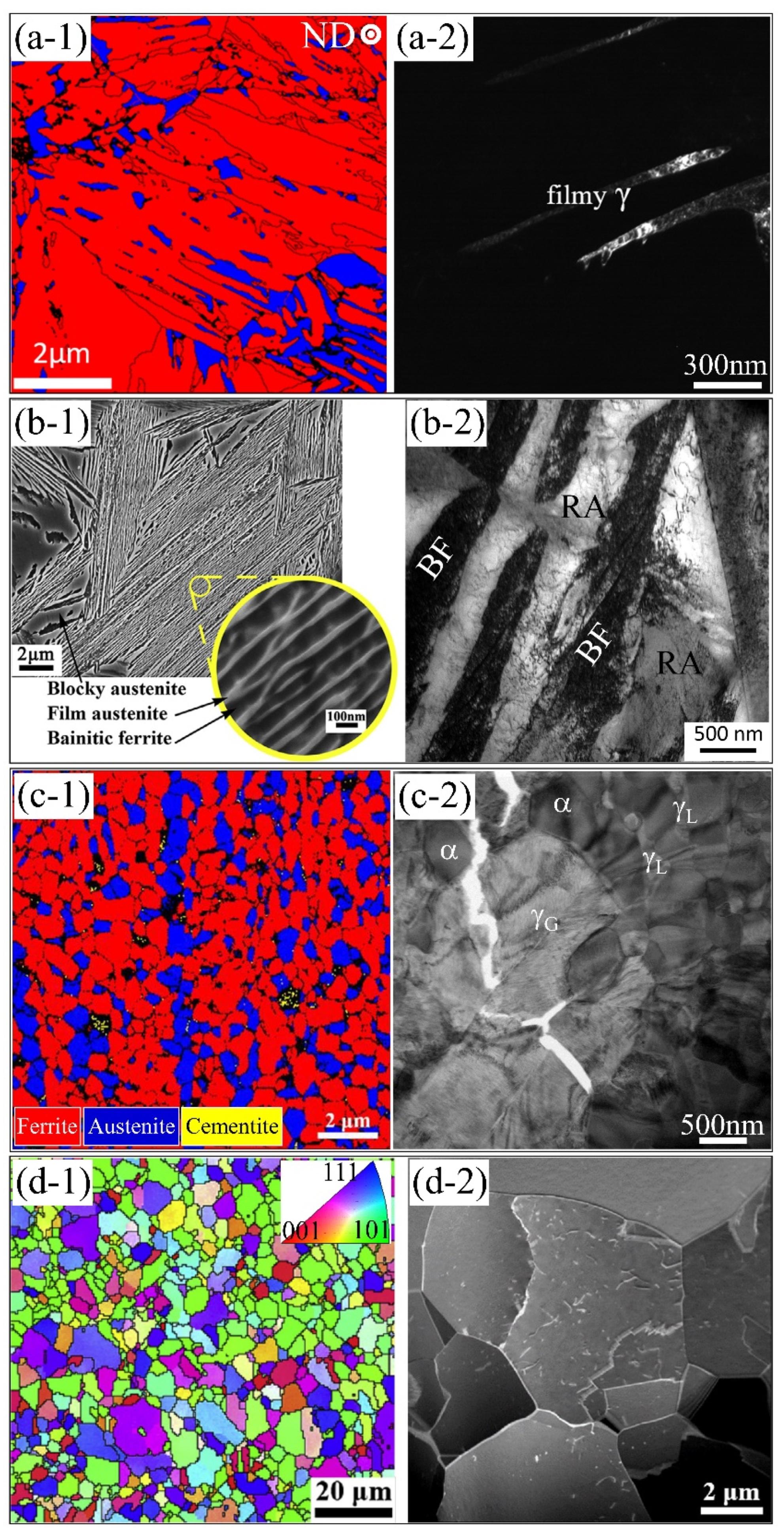
Figure 1. Microstructure of different AHSS containing the metastable austenite grains, including the (a) Q&P steel [56], Reprinted with permission from ref. [56]. Copyright 2018, Elsevier. (b) CFB steel [57,58], Reprinted with permission from ref. [57,58]. Copyright 2015, 2017, Elsevier. (c) medium Mn steel [59,60], Reprinted with permission from ref. [59,60]. Copyright 2019, 2021, Elsevier. and (d) TWIP steel [61,62]. Reprinted with permission from ref. [61,62],. Copyright 2015, 2016, Elsevier. (a-1) and (c-1) are EBSD phase map; (b-1) is SEM image; (d-1) is EBSD orientation map; (a-2) to (d-2) are TEM images. Red color and blue color in (a-1) represent the martensite and austenite, respectively. ND: normal direction. γG: granular austenite; γL: lamellar austenite; α: ferrite.
Metals 11 01927 g001
Figure 2. The P-h curve of individual austenite grain in a medium Mn steel with a dual-phase microstructure of austenite and martensite (Fe-0.45C-10Mn-1Al in wt.%). The dashed line is the Hertzian solution. The solid line is the fitting curve using the GND concept.
Metals 11 01927 g002
Figure 3. (a) TEM bright-field image depicting the defect structure in the austenite grain beneath the indenter. The lower left inset is the selected area diffraction pattern. (b) High-resolution TEM (HRTEM) image displaying the presence of dislocations along the different slip planes. (ce) Magnified view of the rectangle in (a), showing the dislocations under different two-beam conditions. The schematic illustration as shown in (ce) are the tetrahedron demonstrating the orientation of {111} slip plane, and the perfect dislocations on different slip planes [81]. Reprinted with permission from ref. [81]. Copyright 2017, Elsevier.
Metals 11 01927 g003
Figure 4. (a) Engineering stress–strain curve of austenite micro-pillar compressed along [111] crystal orientation. (b) The corresponding SEM micrograph of the austenite micro-pillar after the compression test. The inset in (b) is a tetrahedron indicating the orientation of the {111} slip plane. (c) TEM bright-field image displaying the formation of intensive dislocations in the pillar after compression test. (d) Magnified view of the rectangle in (e) showing the perfect dislocations along the (-1 -1 1) slip plane. € TEM BF image of the same region with different beam -direction [81]. Reprinted with permission from ref. [81]. Copyright 2017, Elsevier.
Metals 11 01927 g004
Figure 5. (a) The P-h curve of individual austenite grain in a medium Mn steel consisting of austenite and ferrite (Fe-0.08C-0.5Si-1Al-7Mn in wt.%) [94]. Reprinted with permission from ref. [94]. Copyright 2015, Elsevier. (b) The P-h curve of individual austenite grain in Q&P steel (Fe-0.41%C-4.0%Mn-1.6%Si-1.0%Cr in wt.%) [28]. The arrows in (a) and (b) mark the pop-in. The insets in both (a) and (b) show the position of the indents. γ: austenite; α: ferrite; α’: martensite. Reprinted with permission from ref. [28]. Copyright 2019, Elsevier.
Metals 11 01927 g005
Figure 6. The detection of the martensitic transformation during the nanoindentation test using different techniques, including the (a) EBSD measurement [106], Reprinted with permission from ref. [106]. Copyright 2020, Elsevier; (b) MFM [105], Reprinted with permission from ref. [105]. Copyright 2019, Elsevier; and (c) FIB-TEM/EBSD [94], Reprinted with permission from ref. [94]. Copyright 2015, Elsevier. (a-1) EBSD phase maps before and (a-2) after indentation test. Red color, yellow color and blue color in (a) represents the martensite, austenite, and cementite respectively. (b-1) SEM image; (b-2) MFM image; (c-1) TEM image; (c-2) EBSD phase map; (c-3) EBSD IPF map. Note that the MFM as shown in (b-2) confirms the free of martensitic transformation in the dual-phase stainless steel.
Metals 11 01927 g006
Figure 7. (a) Schematic illustration for the arrangement of atoms during the martensitic transformation according to the Bain distortion mechanism. (bd) Three possible Bain variants concerning the loading direction [99]. σex: externally applied stress. Black circle and red dot represent the austenite and martensite atoms, respectively. Reprinted with permission from ref. [99]. Copyright 2010, Elsevier.
Metals 11 01927 g007
Figure 8. (a) Simulation setup for the indentation test with spherical indenter on austenite using molecular dynamics. (b) Fraction of martensite during the indentation test at different temperatures. (c) The transformation behavior of the austenite to martensite during compression at varying temperatures. Green color: bcc; dark blue: fcc; light blue: hcp; and red: unknown phase [113].
Metals 11 01927 g008
Figure 9. (a) Engineering stress–strain curves of the austenitic pillars with different orientations in medium Mn steel (Fe-9Mn-0.6C in wt.%). TEM images show the microstructure in deformed austenitic pillars with the orientation of (b) [100] and (c) [110]. The nucleation process of the martensite at the intersection of the stacking faults/twins in the micron-pillars with the orientation of [100]. (d) The calculated critical stress for triggering the deformation twins and martensite. (e) Schematic illustration of the different transformation pathways in the micro-pillars with varied orientations [86,87]. Reprinted with permission from ref. [87]. Copyright 2019, Elsevier.
Metals 11 01927 g009
Figure 10. (a-1) The engineering stress–strain curve of micro-pillar compression test of TWIP steel (Fe-22Mn-0.6C in wt.%). (a-2) SEM image showing the deformed morphology of micro-pillar. (a-3) TEM image showing the presence of large deformation twins in deformed micro-pillar. (b-1) The TEM images show the presence of intensive deformation twins in another deformed micro-pillar of the same steel [74]. (b-2) Magnified view of the rectangle in (b-1). Reprinted with permission from ref. [74]. Copyright 2017, Elsevier. (c) The engineering stress–strain curve and deformation twins in another study [70]. Reprinted with permission from ref. [70]. Copyright 2015, Elsevier.
Metals 11 01927 g010
Figure 11. (a) The comparison between the simulated stress–strain curves and the one obtained by experiments. The inset shows the formation of twins in the austenitic pillar after the compression test. (bd) The simulated stress–strain curve at different engineering strains together with the corresponding morphology of deformation twins [70]. The red color in (bd) represents the deformation twins. Reprinted with permission from ref. [70]. Copyright 2015, Elsevier.
Metals 11 01927 g011
Figure 12. (a-1) The bright-field TEM image depicting the formation of nanometer-sized deformation twins in the micro-pillar generated by emission and glide of stacking faults from pillar surface after the compression test. (a-2,a-3) The schematic illustration of the nucleation of deformation twins by emission and glide of stacking faults in the micro/submicron-austenitic pillar []. Reprinted with permission from ref. [142]. Copyright 2012, Elsevier. (b-1,b-2) The bright-field TEM image demonstrating the generation of complex deformation twins in the austenitic pillar with a diameter of 10 μm. (b-3) The schematic illustration of the nucleation of complex deformation twins [74]. Reprinted with permission from ref. [74]. Copyright 2017, Elsevier.
Metals 11 01927 g012
Figure 13. Critical resolved shear stress (CRSS) or yield stress (YS) for twinning and slip in small-sized single-crystal pillars (Fe-22Mn-0.6C in wt.%). The data are extracted from studies [90,144].
Metals 11 01927 g013
Publisher’s Note: MDPI stays neutral with regard to jurisdictional claims in published maps and institutional affiliations.