Article

Response of Floc Networks in Cemented Paste Backfill to a Pumping Agent

1
Faculty of Land Resources Engineering, Kunming University of Science and Technology, Kunming 650093, China
2
Key Laboratory of Ministry of Education of China for Efficient Mining and Safety of Metal Mines, Beijing 100083, China
*
Author to whom correspondence should be addressed.
Metals 2021, 11(12), 1906; https://doi.org/10.3390/met11121906
Submission received: 29 October 2021 / Revised: 22 November 2021 / Accepted: 23 November 2021 / Published: 26 November 2021
(This article belongs to the Special Issue Green Low-Carbon Technology for Metalliferous Minerals)

Abstract

:
Cemented paste backfill is critical for the development of green mines, the safe exploitation of mineral resources deep underground, and the efficient disposal of solid wastes produced by mining. In this paper, the mechanism underpinning how the pumping agent works was studied. The number, area, and fractal dimension of pores in the microstructure of fresh paste were quantitatively analyzed using scanning electron microscopy (SEM), image processing, and fractal theory, and the response of flocs was investigated. The results show that floc networks disintegrated and the liquid network became the dominant structure under the action of the pumping agent, which enhanced the lubrication and promotion of multi-scale particles. In addition, the force chains became fragile and scattered, diminishing the yield stress of the paste. The pores had a more homogenized dimension and the porosity was 15.52% higher. The increase in the fractal dimension of the pores indicated that there was a higher self-similarity, in terms of microstructure, with a strengthened liquid network. The migration of floc structures contributed to the enhancement of the fluidity and rheology of the paste. This study provides insights into the effects of floc and liquid networks on the performance of paste, and it is of engineering significance in terms of realizing safe and efficient CPB operations.

1. Introduction

Currently, mineral exploitation activities are moving from shallow zones to deep underground in China, and mining enterprises are dedicated to finding new ideas, technologies, and theories for the coordinated development of resources, the economy and the environment under significant administrative and social responsibility-related pressures. Green mining and deep mining have become the two major themes that will be focused on for a long time [1]. However, there are still many challenges in green mining and deep mining. Firstly, considerable safety hazards are hidden in deep mining. Disasters including hard rock bursts and soft rock collapses generally result from high stress in surrounding original rocks and the severe disturbance of tectonic stress, which appear to a severe degree in deep mining activities. In these cases, the backfilling method becomes an indispensable alternative to support the safe mining of deep resources [2]. Secondly, mining operations cause serious environmental pollution. Presently, the tailings produced by mining and mineral processing total 14.6 billion tons and occupy more than 8.7 billion m2 of land; the amount of mine sewage discharged exceeds 10 billion t/a, which causes serious pollution to rivers and leads to significant excess contents of heavy metals in grains [3]. The backfilling method will provide significant support to the construction of green mines [4]. In order to eliminate potential safety hazards in deep underground mining and protect the environment [5], the backfilling method is promising to become the optimum solution for deep mining and green mining in the future [6].
Cemented paste backfill is a process in which multi-scale solids are mixed with binders, admixtures and water to prepare a paste with high concentration and a low segregation rate, which is transported to underground mined-out areas to achieve a predetermined function [7]. Pipeline transportation plays a key role in cemented paste backfill (CPB) operations [8]. As a material with high mass concentration and large yield stress [9], the paste is likely to cause problems such as pipeline wear, high energy consumption and pipe blockage. To solve these problems, it is necessary to improve the fluidity of the paste, which is an important index in paste quality evaluation due to its pipeline transportation [10,11]. Adding a pumping agent can effectively improve the fluidity of the paste and improve the pipeline’s transportation capacity. Therefore, it is of great significance to study the mechanism of pumping agents on paste.
The pumping agent, generally a compound composed of a water-reducing agent, a setting retarder, an air-entraining agent and lubricant, etc., can improve the slurry performance in transportation, so that it can smoothly pass through pipelines without segregation and blockage. It has the functions of fluidization and lubrication, which are appropriate for improving the transportation of slurries with a high concentrations of solids [12]. In recent years, many studies have focused on the effect and mechanism of pumping agents on paste in order to achieve better application effects [13]. Liu, Wang [14] tested the effects of various dosages of a pumping agent on the rheological performance of paste and concluded that it can effectively improve rheological performance and is suitable for CPB in the mine of interest. Ercikdi, Cihangir [15] studied the rheological and mechanical properties of CPB with the addition of three different water-reducing agents, and proposed that the use of a pumping agent can not only ensure the good fluidity of paste but also greatly increase its concentration, thus enhancing the mechanical strength. Yang, Wang [16] discussed the reduction in the resistance of CPB with the use of pumping agent and the mechanism of paste slump loss under long-time action, and it was suggested that the pumping agent can be effectively applied to reduce resistance and alleviate pipe wear in the pipeline transportation of paste. Wu, Ruan [17] found through experiments and numerical simulation that the loss of resistance of pipeline transportation is much higher for paste with high mud content but without pumping agent compared to that with pumping agent, and to that with low mud content but without pumping agent. It is particularly important to add pumping agent to paste with a high mud content.
The manner in which the pumping agent improves the fluidity of pastes and reduces pipeline resistance lies in its impact on the CPB microstructure. Wu, Liu [18] found that there is a three-dimensional floc network in the paste, which shows a structural flow. The rheological properties of paste and the pipeline resistance are closely related to its internal structures. Li, Wang [19] believe that the pumping agent affects the setting of paste by changing the number and size of flocs, as well as the porosity and hydration reactions. Zheng and Gu [20] measured the total porosity and pore size distribution of hardened CPB by using a mercury intrusion method and concluded that the porosity and average pore size were reduced by adding water-reducing agent. Zuo, Wang [21] proposed that the water-reducing agent in the pumping agent aims to destroy the flocs formed by the aggregation of powder particles, and that the particles will be dispersed and uniformly distributed. Thereafter, the water enclosed in flocs can be released, which will improve the paste’s fluidity. Zheng, Zhao [22] found that cement and fine tailings net slurry have similar floc structures without water-reducing agent under microscope, and that the water-reducing agent can destroy the flocs with a strong bonding, leading to more free water being released and better paste fluidity being obtained, and thus, the agent will be a prominent admixture for the preparation of CPB. Yang, Wu [23] constructed a microstructure model of fresh CPB and proposed that the pumping agent works by breaking flocs to release enclosed water. Wu, Ai [24] confirmed that, according to their observations of microscopic images of CPB, the flocs were destroyed by pumping agent. Zhang, Wu [25] also found that the pumping agent destroyed the floc and the yield stress was reduced by using the environmental scanning electron microscope (ESEM).
Pumping agents have a significant influence on the fluidity and rheological properties of pastes; however, at the micro-level, the mechanism underpinning this influence has not been fully figured out and it also needs to be further studied from a mechanical point of view. Quantitative analysis and mechanical analysis of the mechanism of the pumping agent at the micro-level can provide a deeper understanding of its action on the microstructure of the paste and allow better preparation of CPB, based on its fluidity, for the application and development of the CPB technology.
In this study, the mechanism of the pumping agent and the rheological properties of the paste were analyzed by combining the macroscopic rheological properties and microstructure of paste on the theoretical basis of paste flocculation mesh. By adding different dosages of pumping agent, the paste’s microstructure will gradually change. Combined with an environmental electron microscope scanning microscopic experiment, image processing technology and fractal theory, the change in state of the paste’s microstructure will be quantitatively analyzed. Meanwhile, the gradual change of the microstructure will lead to corresponding changes in the paste’s rheological properties. The mechanism of action of the pumping agent and the mechanism underpinning the changes in the paste’s rheological properties were studied from the micro scale by associating the paste’s microstructural change with the corresponding macro rheological property state change.

2. Materials and Methods
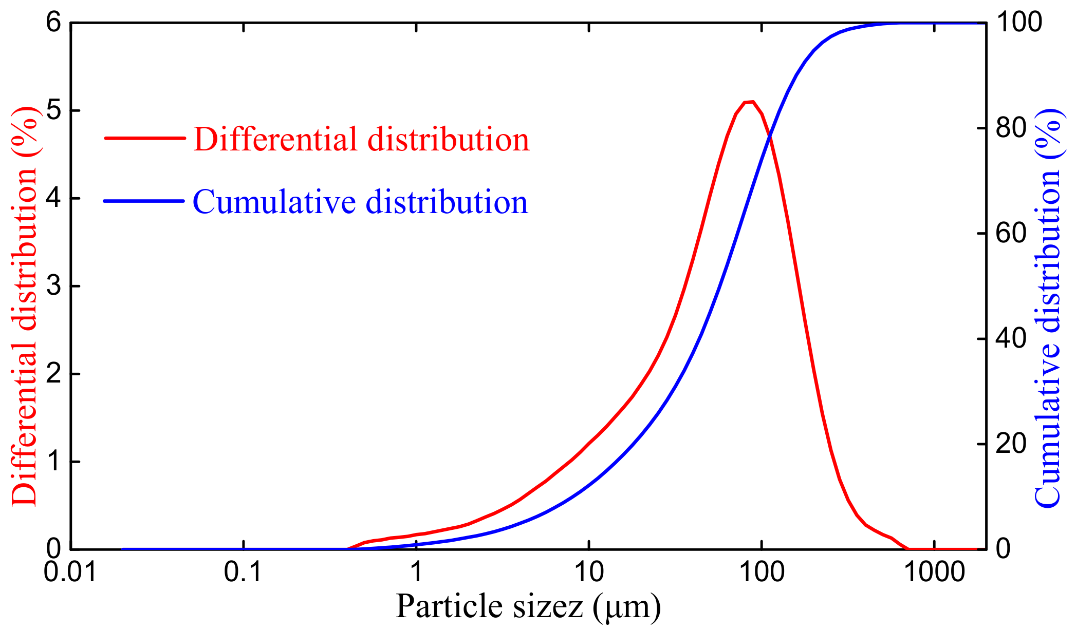
2.1. Materials

Unclassified tailings were taken from a mineral processing plant in Gansu, China. Gansu is located in the hinterland of Northwest China, between 92 degrees (20 min)–108 degrees (42 min) east longitude and 32 degrees (31 min)–42 degrees (50 min) north latitude. The mining area is located in the northwest of Gansu, and the location information is shown in Figure 1. The whole mining area is characterized by monoclinic structures and developed fault poles. The particle size distribution of unclassified tailings was analyzed by using a TopSizer laser particle analyzer (OMEC, Zhuhai, China), as shown in Figure 2. It is established that fine particles will affect the rheological properties of the paste [26]. The contents of −5 μm, −10 μm, and −20 μm were 6.29%, 12.21% and 21.67%, respectively. D10, D30 and D60 were the diameters of sieve holes with accumulative contents of 10%, 30% and 60%, respectively. The values were D10 = 8.1 μm, D30 = 30.7 μm, d60 = 72.4 μm. The tailing was composed of particles of different sizes. CU and the curvature coefficient CC were used to characterize the uniformity of particle size composition of the material. Generally, when CU ≥ 5, the size distribution of sand particles was large and the grading was good. CC represents the continuous gradation of sand. Generally, when CC = 1~3, the gradation was good and the density of sand was good. Therefore, CU and CC were used to evaluate the composition of the tailings. The non-uniformity coefficient CU was 8.94 and the curvature coefficient CC was 1.61, indicating that the particles were distributed over a wide range of size with good compactness, continuity and gradation. The mean density of the tailings was 2.852 t/m3. The loose and compact bulk density were measured to be 1.229 t/m3 and 1.545 t/m3, and the loose and compact porosity were 56.9% and 45.8%, respectively. The chemical components of the tailings are shown in Table 1. The tailings could be classified as weakly alkaline inert materials with an alkali coefficient of 0.699 and an activity coefficient of 0.213.
Crushed mine waste rocks, with diameters below 12 mm, were utilized as coarse aggregates. The average particle size was 4.12 mm. The mean density of the rocks was 2.809 t/m3. The loose and compact bulk density were measured to be 1.615 t/m3 and 1.844 t/m3, and the loose and compact porosity were 42.5% and 34.4%, respectively.
The composite Portland cement, P.C32.5R, was utilized as the binder, of which the chemical compositions are shown in Table 1.
The pumping agent used, JKJ-NF, was produced by Jinchang Building Materials Chemical Plant, Jinchang, China. This product was selected according to the preliminary comparison of slumping results. JKJ-NF pumping water reducer is a cement concrete pumping agent with naphthalene sulfonated formaldehyde condensate superplasticizer as the main component, which is composed of naphthalene sulfonated naphthalene formaldehyde superplasticizer, air entraining agent, retarder, water retaining agent, slump inhibitor, etc. It is a brown-yellow powder, with a fineness of less than 1.25 mm, and a solid content of more than 94%, and it is non-toxic and non-combustible. Other characteristics include: no corrosion to reinforcement; pH 5–6, water-insoluble matter ≤ 1%, sodium sulfate content ≤ 10%, and chloride ion content ≤ 0.5%. The main features include a high water-reducing rate, an obvious improvement of mixture workability, good pumpability at low and room temperature, and good compatibility with cement.
Tap water, at a pH value of 7.9, was used, which met the experimental requirements for CPB preparation.

2.2. Testing Procedures

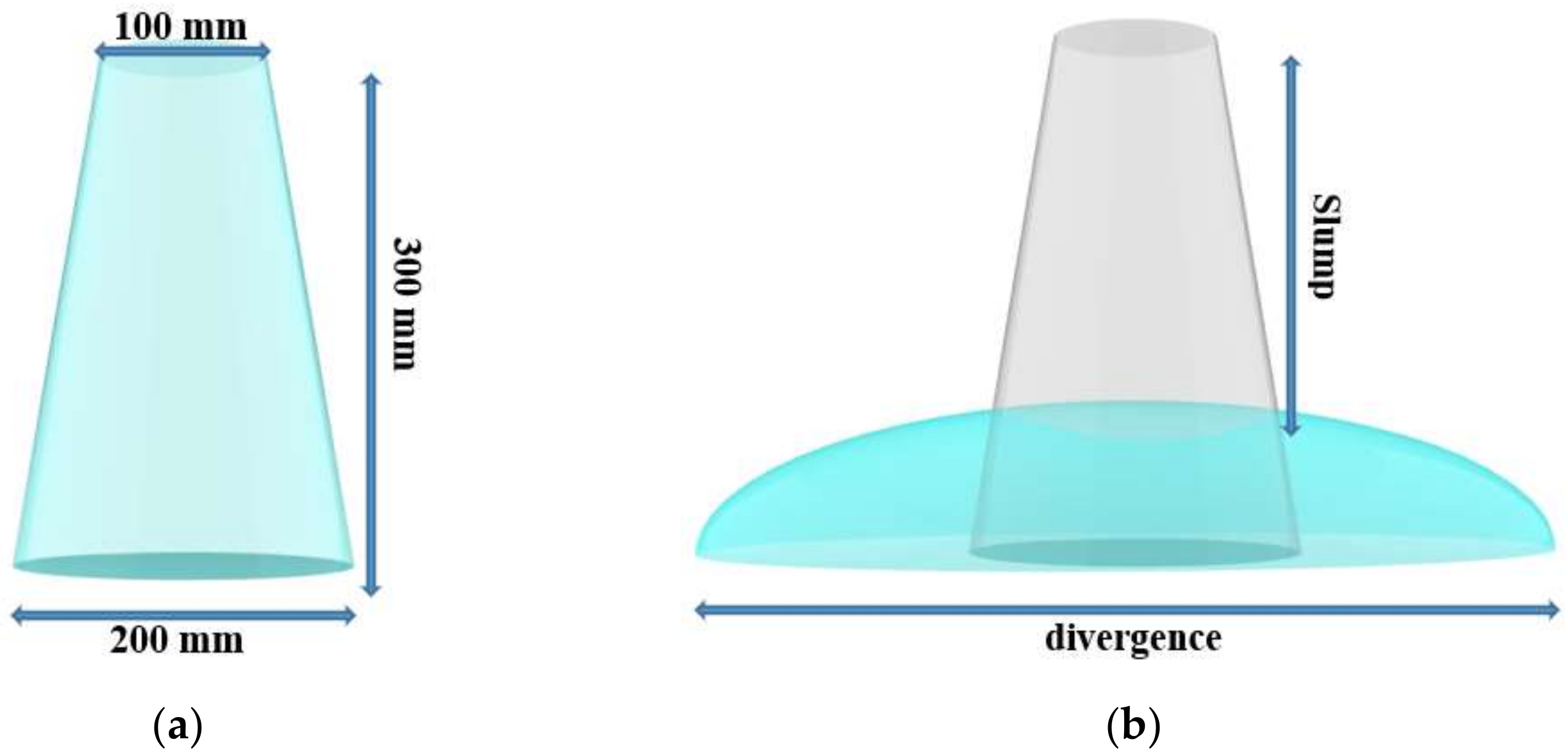
2.2.1. Fluidity Tests

The fluidity of CPB refers to its performance in terms of of how it flows by itself or under pump pressure, and its capability to maintain a certain flowing state uniformly and stably. Generally, the slump test can reflect the fluidity of paste and a desired slump value is around 23~26 cm [27].
The CPB samples were prepared at a cement content of 280 kg/m3, a solid concentration of 79 wt.%, and the ratio of tailings to waste rocks was 1:1, with various pumping agent dosages of 0, 2%, 3%, 4% and 5% relative to cement weight. The dimensions of the slump cone are shown in Figure 3a. In the slumping tests, the CPB was filled into the slump cone and compacted before the cone was lifted at a constant rate, which was completed within 5~10 s. The maximum drop of the paste was the slump and the diameter of the slumping was the divergence, as shown in Figure 3b. The latter is generally an average value of the longest and shortest diameters. To ensure the reliability of the experimental results, three tests were conducted for each CPB, and the average value was adopted.

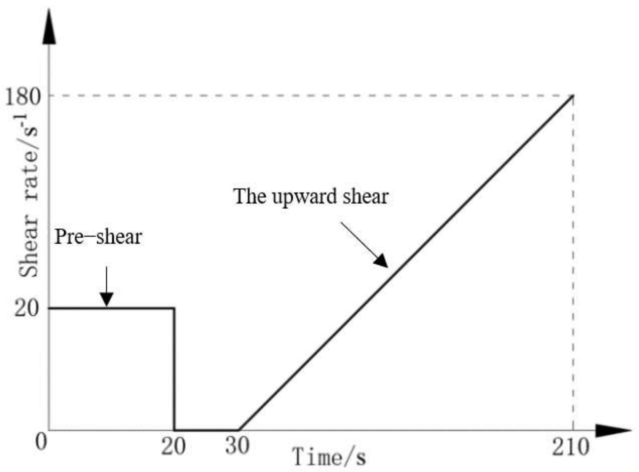
2.2.2. Rheological Tests

The proportioning of CPB samples used in the rheological tests was consistent with that in the fluidity tests. The experiments were conducted with a Brookfield R/S plus four-blade vane rheometer, and the vane diameter and height were 20 mm and 40 mm, respectively. According to the characteristics of the paste, the yield stress was measured using a controlled shear rate mode (CSR) [28,29]. The freshly prepared paste was tested at room temperature. A volume of 480 mL CPB in a beaker was pre-sheared at a constant shear rate of 15 s−1 for 20 s. Thereafter, the CPB was left standing for 10 s before undergoing an increasing shear from a shear rate of 0 to 180 s−1. From 30 s to 210 s, a data point was collected every second, and a total of 180 data points were collected, as shown in Figure 4.
The shear stress-shear rate curves obtained in the rheological tests were analyzed using the Bingham model to calculate the yield stress and plastic viscosity. The Bingham model is one of the classic models used for characterizing viscoplastic fluids with yield stress, and it describes the rheological properties of yielding fluids when their viscosity is independent of the shear rate (constant). The Bingham model is of good applicability to CPB and is widely used [30,31]. Its mathematical model expression is shown in formula (1):
γ ˙ = 0 τ < τ y τ = τ y + η p γ ˙ τ τ y
where τ is the shear stress, τy is the yield stress, ηp is the plastic viscosity, and γ ˙ is the shear rate.

2.2.3. ESEM Experiments

The microstructure of the paste was observed by using an environmental scanning electron microscope (FEI Quanta 200, FEI, Eindhoven, Netherlands). The CPB samples were prepared at a cement content of 280 kg/m3 and a solid concentration of 79 wt.%, and the ratio of tailings to waste rocks was 1:1. Two conditions were set: no pumping agent and 5% pumping agent. Fresh samples were prepared at room temperature for the ESEM test. The samples without pumping agent and those with a proportion of 5% underwent observation to analyze their effects on the microstructure of the paste. In order to better reflect the changes in the paste, the scanning was carried out at 1000 times, 2000 times and 5000 times magnification, respectively, in order to achieve a relatively comprehensive comparison.

3. Results

3.1. Experimental Results

1.
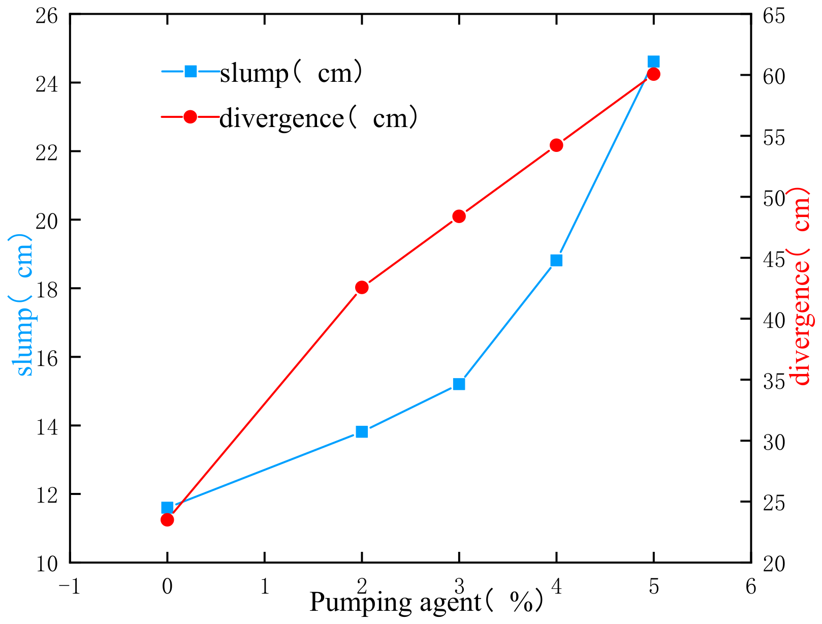
The results of the slump and divergence of paste with different contents of pumping agent are shown in Figure 5. The following trend was identified: the better the slump and divergence, the stronger the paste flow performance and the smoother the pipeline transportation flow. It can be seen that the two parameters were at a relatively low level before the pumping agent was added. As the dosage increased, the slump and divergence gradually increased. When the dosage reached 5%, the slump increased from 11 to about 24 cm, and the divergence increased from 25 to 60 cm. This shows that the pumping agent can effectively improve the fluidity of paste.
2.
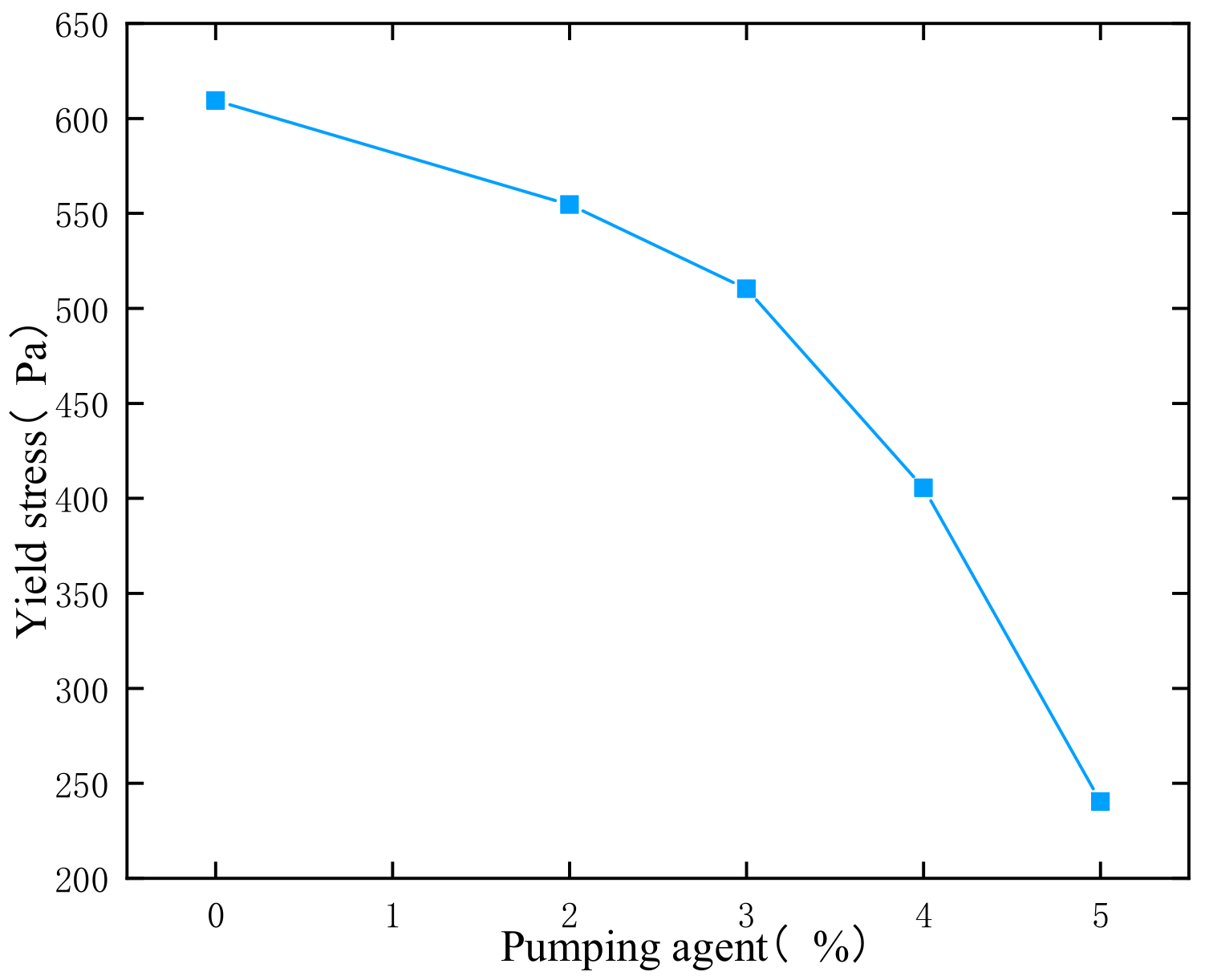
The yield stresses of paste at different dosages of pumping agent are shown in Figure 6. The paste with large yield stress had poor fluidity compared to the paste with small yield stress, which was found to be more likely to have greater pipeline friction in the transportation process and more likely to lead to pipe plugging. As shown in Figure 6, the yield stress of paste without pumping agent reached 600 Pa and did not have fluidity. With the increase in pumping agent, the yield stress gradually decreased. When the content reached 5%, the yield stress decreased to 200 Pa, about 1/3 of the original quantity, and the rheological properties of the paste were significantly improved.
3.
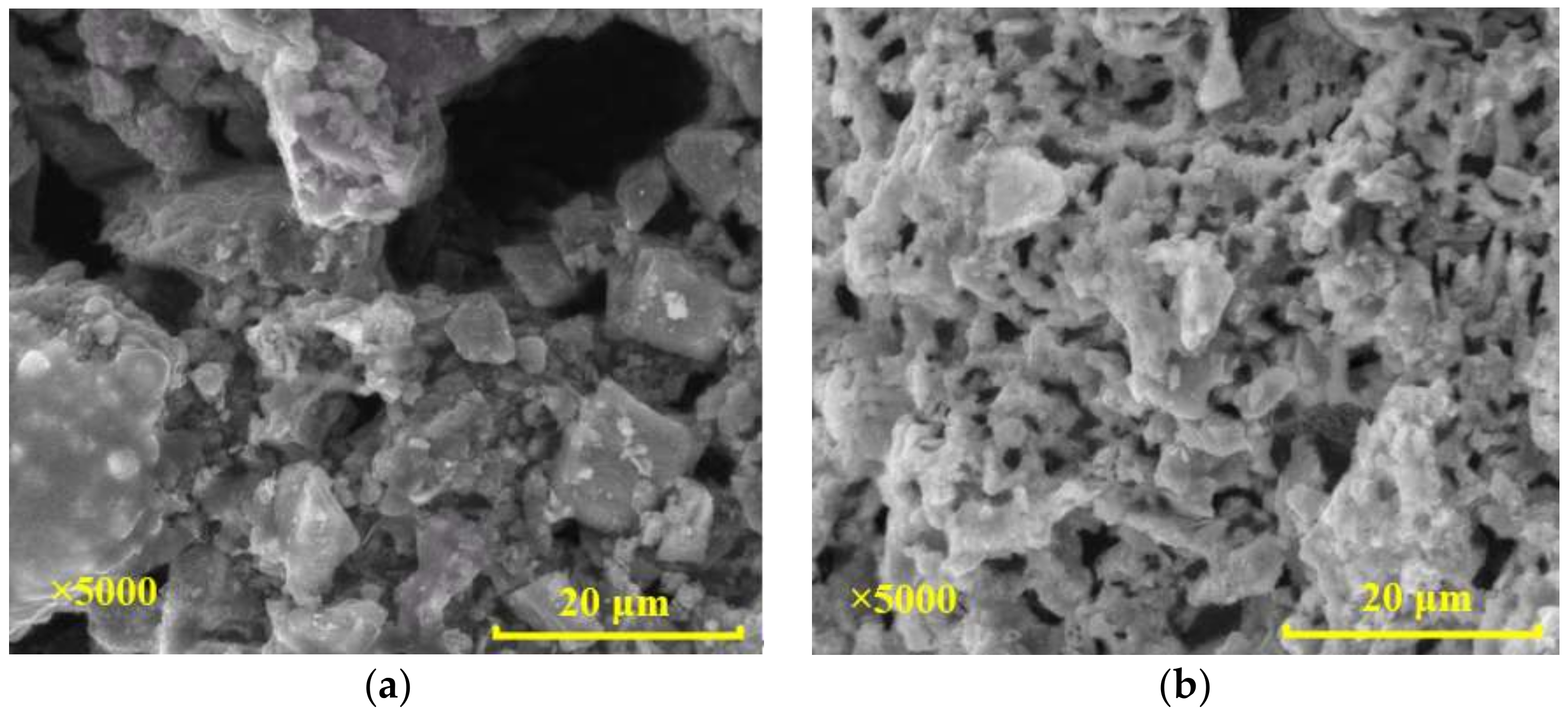
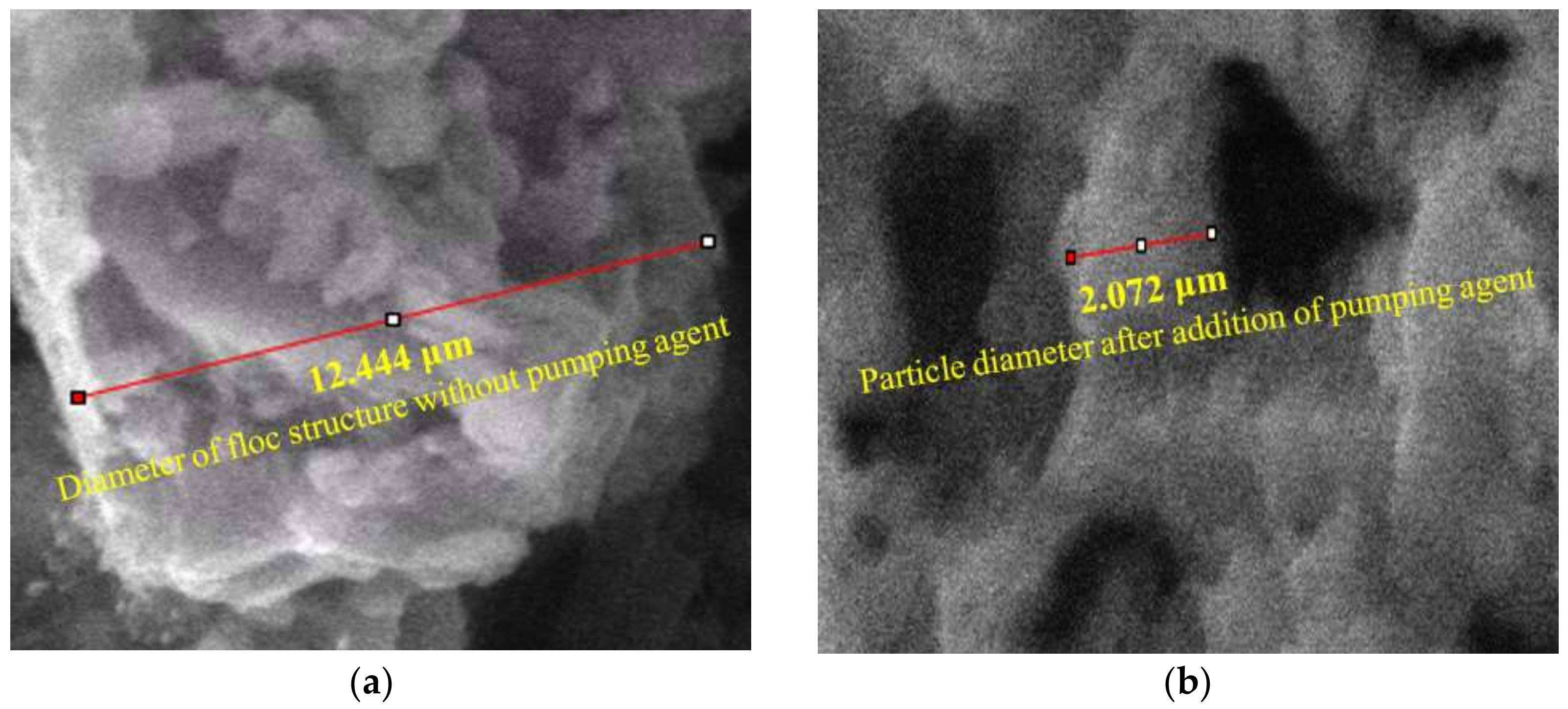
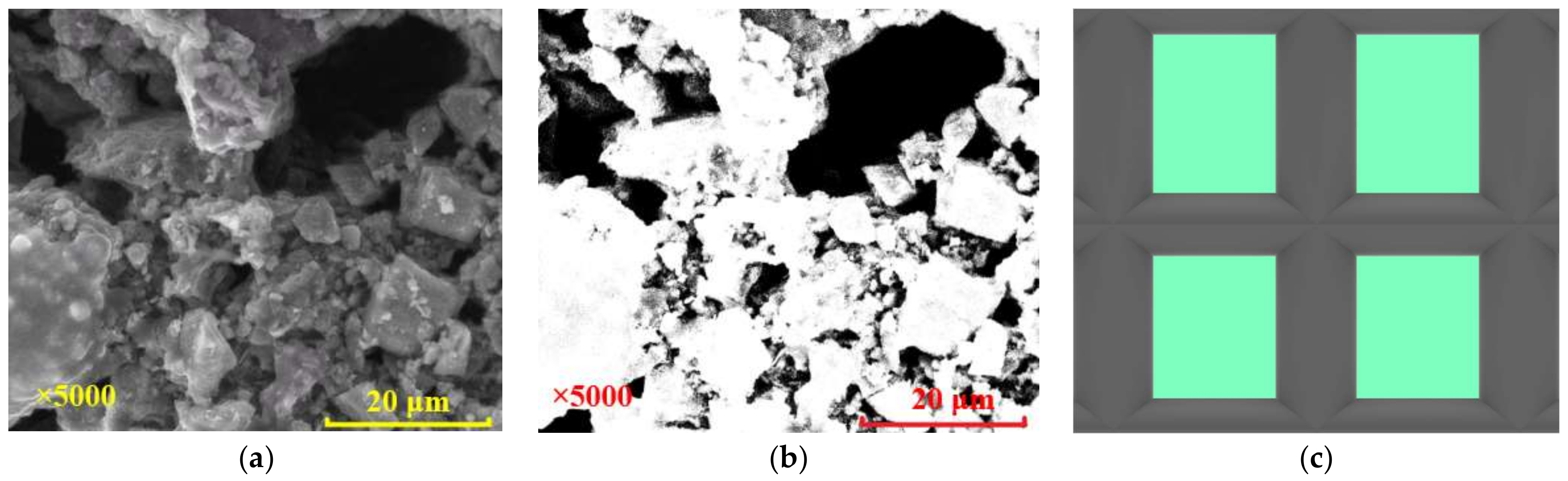
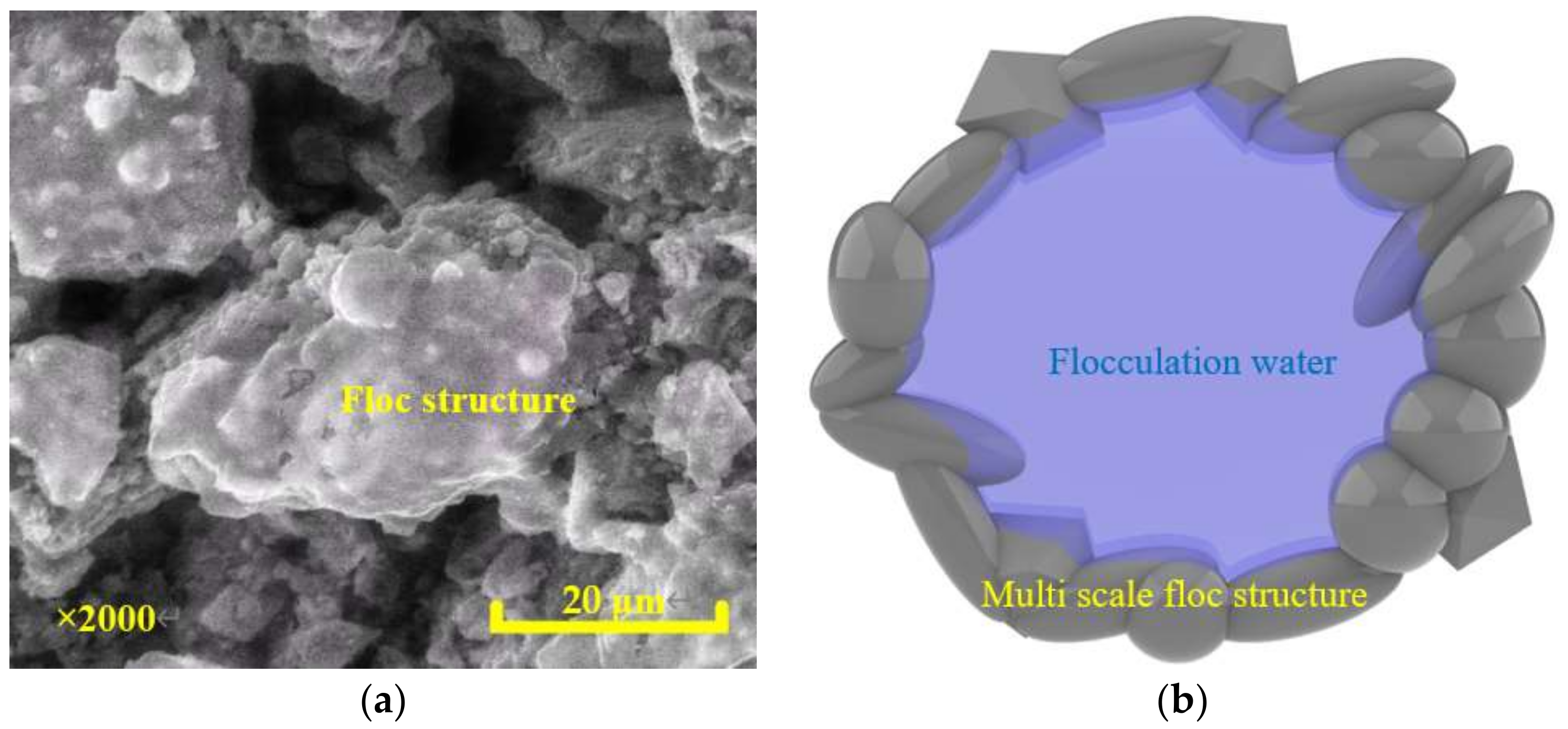
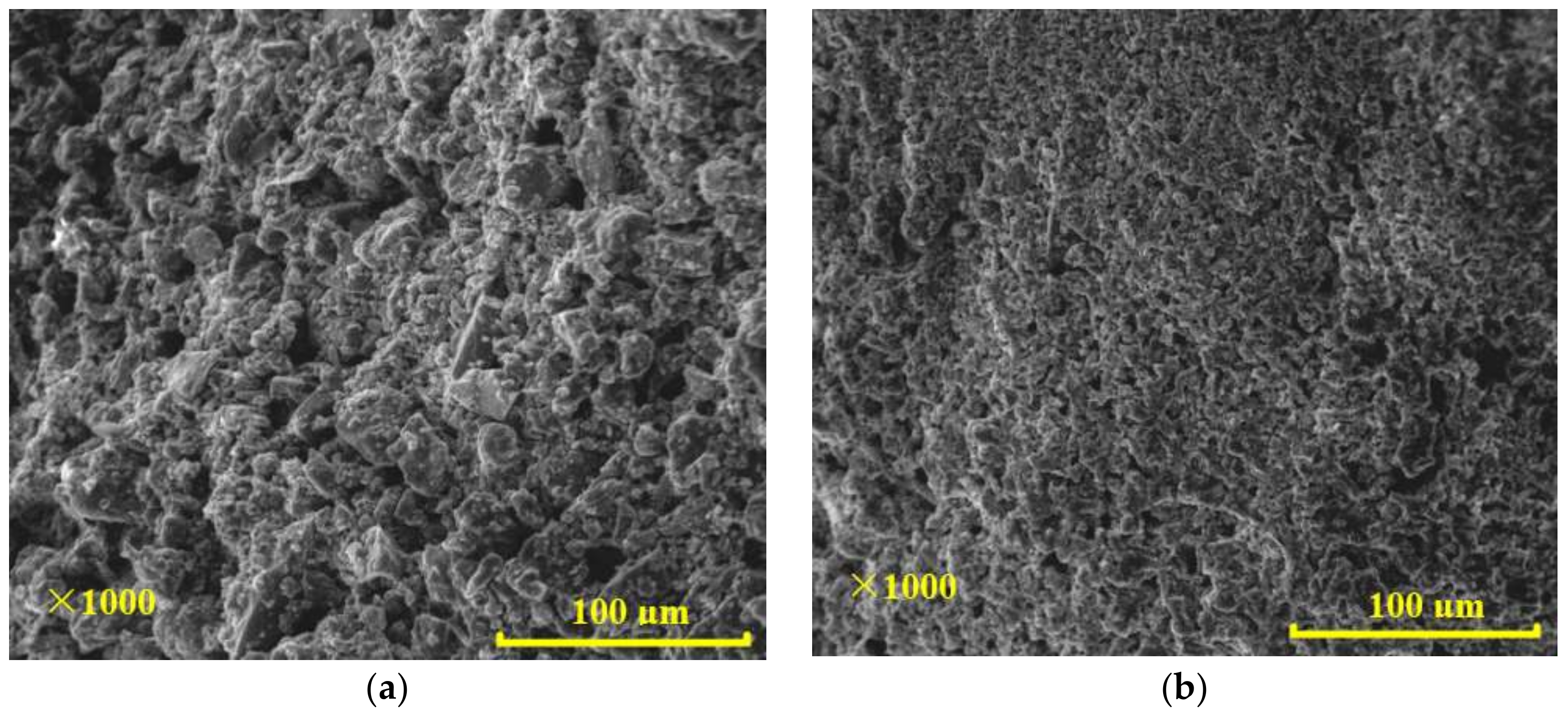
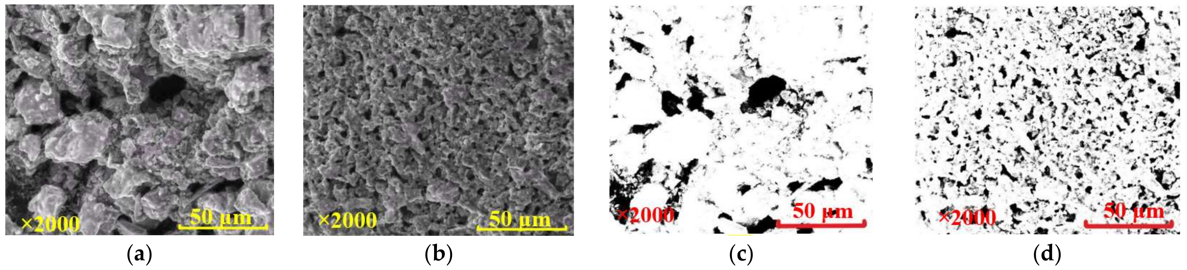
The ESEM images facilitate an insight into the microstructure of freshly prepared paste. As shown in Figure 7, the particles clustered into a dense structure and the pores between the clusters had a small number (a single pore area is large) and a nonuniform distribution without pumping agent. For those pastes that included pumping agent, flocs were disintegrated into smaller and uniformly-distributed particles; although the number of pores increased, the area of individual pores between particles decreased and the pore distribution was relatively uniform.
The results show that pumping agent can significantly reduce the yield stress of paste and improve its rheological properties. Moreover, it can enhance the fluidity of paste and, thus, the related issues in the pipeline transportation of paste, which occur as a result of excess yield stress and poor fluidity, can be tackled. The macroscopic performance is generally a result of the changes in the microstructure [32]. Next, the article will further study the mechanism of action of the pumping agent from the micro perspective.

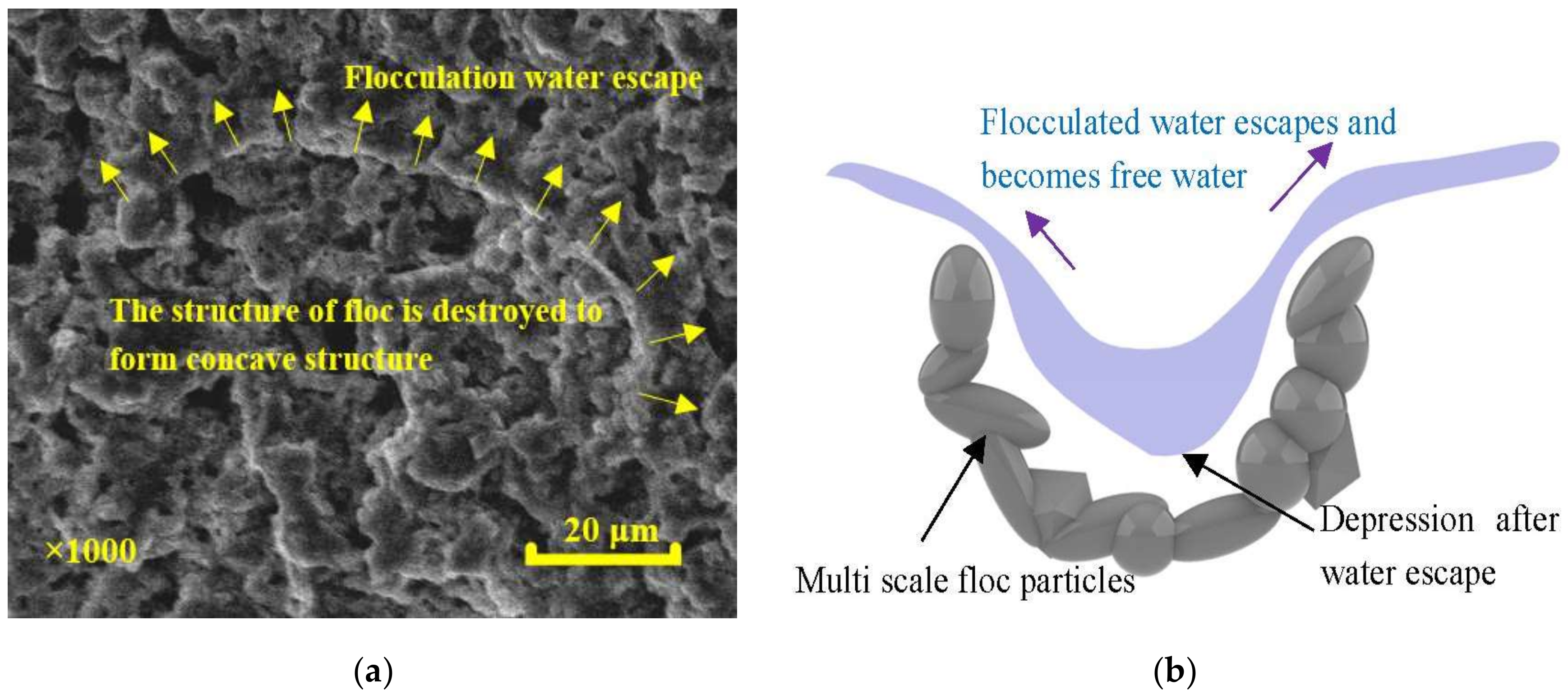
3.2. Effects of Pumping Agent on Flocs

Solids in CPB, including cement, tailings and waste stones, have a wide range of particle sizes. In the initial mixing process, flocs formed among particles, mainly as a result of interparticle force [33], as shown in Figure 8 [23,34].
The flocculation partially turned the free water into flocculated water, leading to a decrease in the mass fraction of free water, and the latter had an evident influence on the paste’s fluidity and rheology. The friction resistance between particles increased with the reduced lubrication of the water, thus increasing the yield stress and plastic viscosity of the paste. Free water could provide hydrodynamic force to drive the particles in the paste to move forward, and less free water led to the weakening of the hydrodynamic force and also to poor fluidity. A number of particles that could not move forward in a steady state due to lack of force were likely to cause problems such as settlement, segregation and pipe blockage.
The pumping agent was able to break down the floc structure as a result of adsorption and dispersion effects, and thereafter, the water enclosed in the flocs could escape and turned to be free water. The increase in the mass fraction of free water could improve the rheology and fluidity of the paste. It can be observed in SEM images that the floc structure was destroyed and a concave structure formed after the escape of flocculated water, as shown in Figure 9.
Furthermore, the flocs in the paste were generally larger than particles, particularly those huge ones, which caused a number of particles to be closely arranged and, thu, to have a nonuniform distribution. This led to a higher collision probability and larger contact area between the particles, thus increasing the shearing between flocs and leading to a larger yield stress. The diameters of typical flocs and particles were calculated by using ImageJ, and the results are shown in Figure 10. It can be seen that the diameter of a typical floc was larger than 10 microns and the pumping agent could break the flocs into small flocs and particles of several microns, thus obtaining a more uniform microstructure of CPB.
There were many flocs in the paste as shown in Figure 11a, which shows that the paste had many dense flocs that were coagulated together before the pumping agent was added. Flocculation could produce flocs of large diameter, reduce the proportion of free water, and cause the particles to be unevenly distributed and reduce their porosity, which significantly reduced the paste’s fluidity. In order to improve the fluidity and rheology of the paste, it was necessary to destroy these flocs, and the pumping agent could break most of them. As shown in Figure 11b, the particles became clearly smaller and uniformly distributed.

3.3. Evolution of Force Chains under the Effect of Pumping Agent

The flocs were destroyed under the action of pumping agent to different extents. The yield stress of the paste was reduced and its fluidity and rheology were improved. The force chain structure in the microstructure was constructed on the basis of SEM images, as shown in Figure 12 and Figure 13, which can reflect the changes of force chains under the action of the pumping agent. The changes in force chains can explain the changes in energy reserve and yield stress.
Figure 12 shows that the force chain was thick and the voids between force chains were large even over a small number, forming an enhancement effect for the paste without the pumping agent. The fully dispersed force chain was defined as the unit force chain. The force chain of the paste without the pumping agent is shown in Figure 12c. The shear stress required to overcome the yield stress increased linearly, and the growth was related to the number of flocs and the tightness of bonding.
For the paste that included pumping agent, the force chains were thinner and evenly distributed, and were similar to the unit force chain, while the voids were smaller and occurred in larger numbers, as shown in Figure 13c. When the unit force chain was damaged by a small shear stress, the fracture coefficient of force chain increased and the shear stress required to move the flocs increased nonlinearly due to the influence of the action time and the recombination coefficient. The force chain structure model is shown in Formula (2) [18]. The pumping agent could change the structure of force chains in paste, thus reducing the stress required to start a flow and improving the fluidity and rheology of the paste.
τ = a × n × τ 0 / f t , 1 a
where τ is the shear stress for breakage, τ0 is the yield stress of the unit force chain, a is the recombination coefficient, indicating the ratio of the force chain to the unit force chain, n is the degree of freedom for the linkage, indicating the number of force chains linked, and f t , 1 a is the fracture coefficient, which is positively correlated with the action time and the reciprocal of the recombination coefficient.

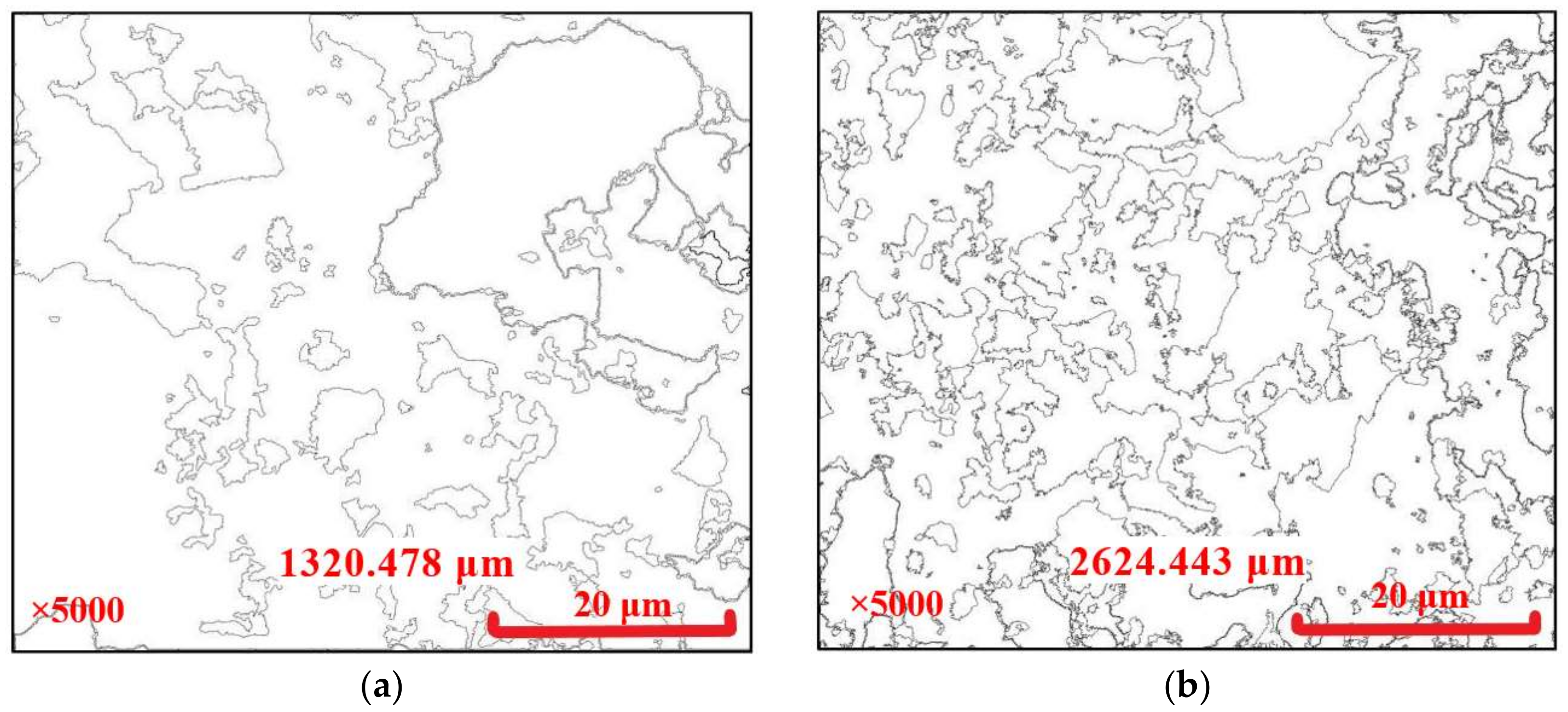
3.4. Evolution of Liquid Network

Liquid networks are composed of connected pores and free water, which is central to the lubricating and pushing of particles. A fully developed liquid network that has more branches and sufficient contact with particles will present a better performance in terms of lubrication and promotion, corresponding to better fluidity and rheology properties. The abundance of liquid networks can be quantitatively evaluated by the boundary line between pores and particles, that is, the wetted perimeter. In this study, this was measured using ImageJ, on the basis of Figure 11b and Figure 12b, and the results are shown in Figure 14.
The length of boundaries for the paste without pumping agent was measured to be 1320.478 um, as shown in Figure 14a, and this value was 2624.443 um for the paste that had pumping agent added, which was nearly twice as long as the former, as shown in Figure 14b. The addition of pumping agent caused the particles to more fully make contact with the free water, and the liquid network was more developed. This was more favorable for lubrication and promotion on particles. Therefore, the pumping agent was able to enhance the liquid network, thus improving the fluidity and rheology of the paste.

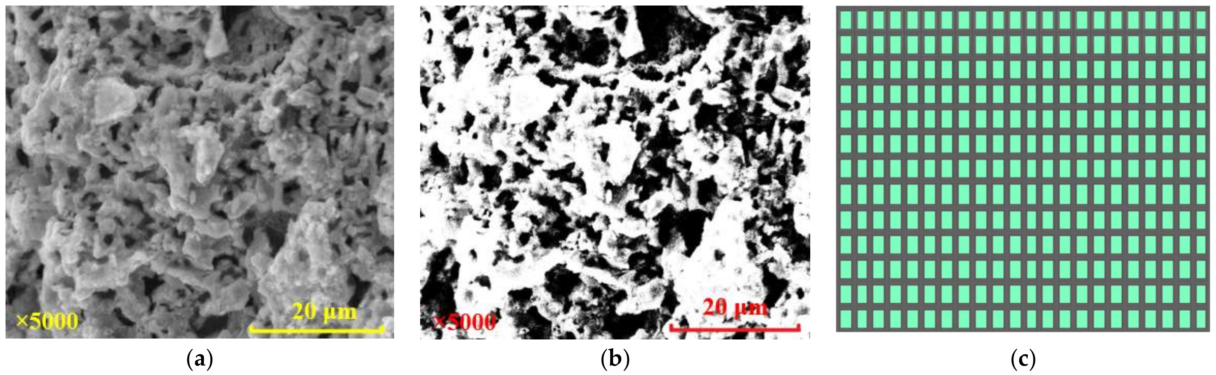
3.5. Analysis of Pore Area and Fractal Characteristics

A quantitative evaluation of the area of pores in the images was conducted to provide a direct illustration of the effect of the pumping agent on the porosity and distribution of pores, as well as their dimensions, and the minimum and maximum pore area. The processed images are shown in Figure 15a,b with a magnification of 2000 and the obtained binary pictures are shown in Figure 15c,d.
The area of pores, as shown in Figure 15c,d, were measured using ImageJ. Prior to measurement, the threshold had been set and binarized. The part where the particles were located is white and the part where the pores were located is black. The measurement and analysis module of ImageJ was used to statistically analyze the number and area of black areas, to number and calculate each closed black pore area, and to analyze their areas. With the pore distribution data obtained, the pore distribution was illustrated and is shown in Figure 16. Figure 16a shows that when no pumping agent was added, the number of extracted pores was 109, the maximum pore area was 411.301 μm2, there were two pores of more than 300 μm2, there were also nine pores of more than 50 μm2, and the pore area span was from several square microns to 400 square microns. Figure 16b shows that after adding the pumping agent, the number of pores was 422, the maximum pore area was only 79.887 μm2, there were only two pores above 50 μm2, and the pore area span was between a few square microns and 80 square microns. The porosities were 10.89% and 12.58% for samples without and with pumping agent, respectively. This shows that the use of the pumping agent led to a higher number of pores and a uniform pore distribution.
ImageJ has a built-in box counting dimension analysis module, which can directly process binary images. The box counting dimension reflects the occupancy of the fractal body in the space. Let F ∈ Rn be any non-empty bounded subset, Nx(F) represent the minimum number of covering f sets, and the maximum diameter of the set be x, then the upper and lower fractal box dimensions of F can be obtained as shown in Equations (3) and (4), respectively. When the two equations are equal, take this value as the fractal box dimension of F.
Dim B ( F ) = lim x sup lg N x ( F ) lg x
Dim B ( F ) = lim x inf lg N x ( F ) lg x
The binary images, shown in Figure 15c,d, were processed using ImageJ based on the fractal theory of the box-counting dimension, and the results are shown in Figure 17. The fractal dimension of the pores was 1.6431 for the paste without pumping agent, with a correlation coefficient of 0.99789. This figure became 1.7559 after adding pumping agent, with a correlation coefficient of 0.99561. The increase in the fractal dimension indicated that the self-similarity at the micro level was higher [35]. Furthermore, the pore structure became more complicated [36], the pore distribution became more uniform, and the proportion of pores was higher. These changes improved the development of the liquid network in the paste and enhanced its fluidity and rheology. The following pattern was observed: the larger the fractal dimension of the pores, the better the fluidity and rheology of the paste.

4. Conclusions

The characteristics of floc networks exert a dominant effect on the fluidity and rheology of paste. A closely connected and complex floc network tends to correspond to strong force chains and underdeveloped channels for free water. In this case, the paste needs to overcome a higher yield stress in order for the flow to begin. In contrast, the pumping agent will break the floc network and a liquid network will form, which will play a dominant role; as such, the lubrication and promotion of multi-scale particles will be enhanced and, thus, the fluidity and rheology of the paste will be improved. The main conclusions are as follows:
1.
The pumping agent could effectively improve the fluidity of paste and led to a larger slump and divergence. Flocs of more than 10 microns were, to a significant extent, broken into particles of several microns. In addition, the pumping agent caused the force chains to become fragile and scattered and, as a result, caused the yield stress to decrease.
2.
The pumping agent could facilitate the development of liquid networks. The boundaries between the pores and the particles increased from 1324.478 to 2624.443 um after using the pumping agent, allowing the particles to fully make contact with the free water. This allowed the lubrication and promotion of particles.
3.
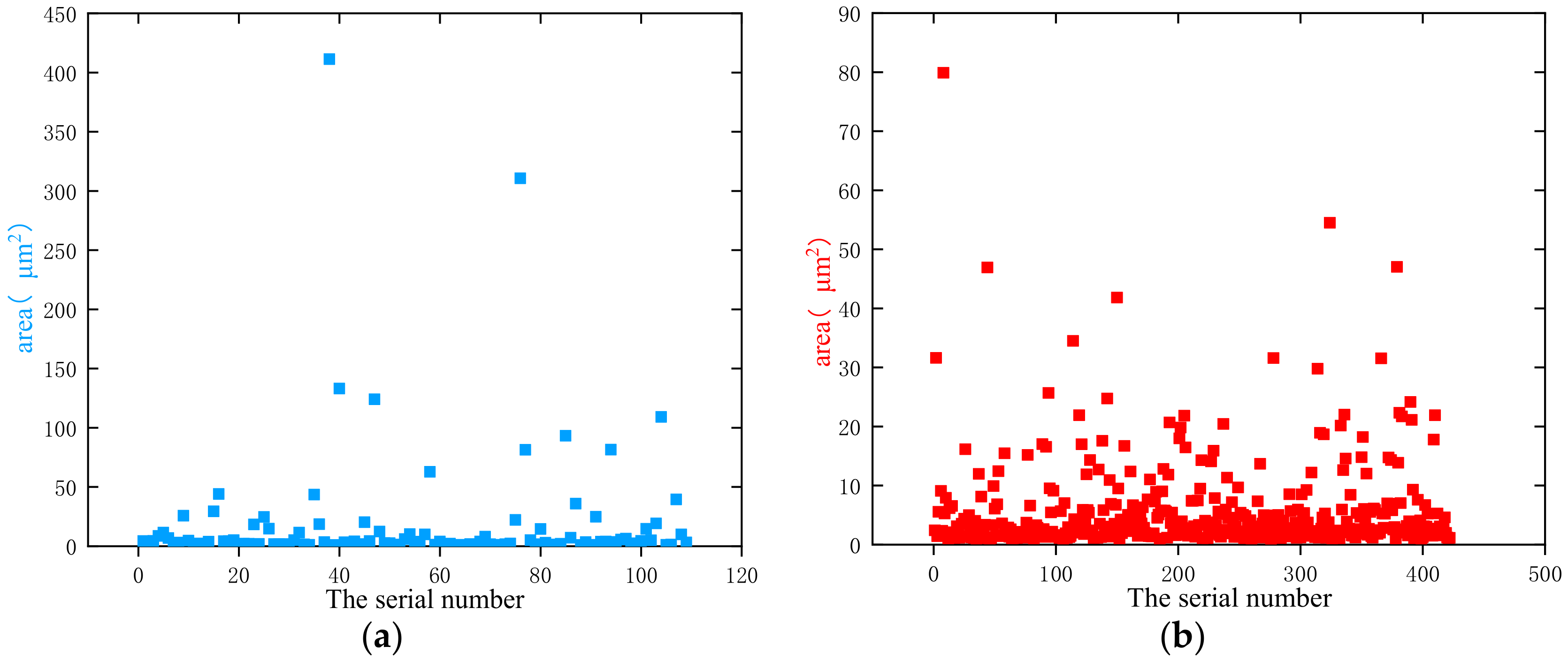
There were 109 pores nonuniformly distributed in the specified area of the paste without pumping agent. The maximum number of pores reached 411.301 um2 and the proportion of pores was 10.89%. In contrast, for paste with pumping agent added, the number of pores increased to 422, and these were of relatively uniform distribution, with a maximum pore area of 79.887 um2 and a pore proportion of 12.58%. The addition of pumping agent contributed to the development of a liquid network with more pores and more uniform pore distribution.
4.
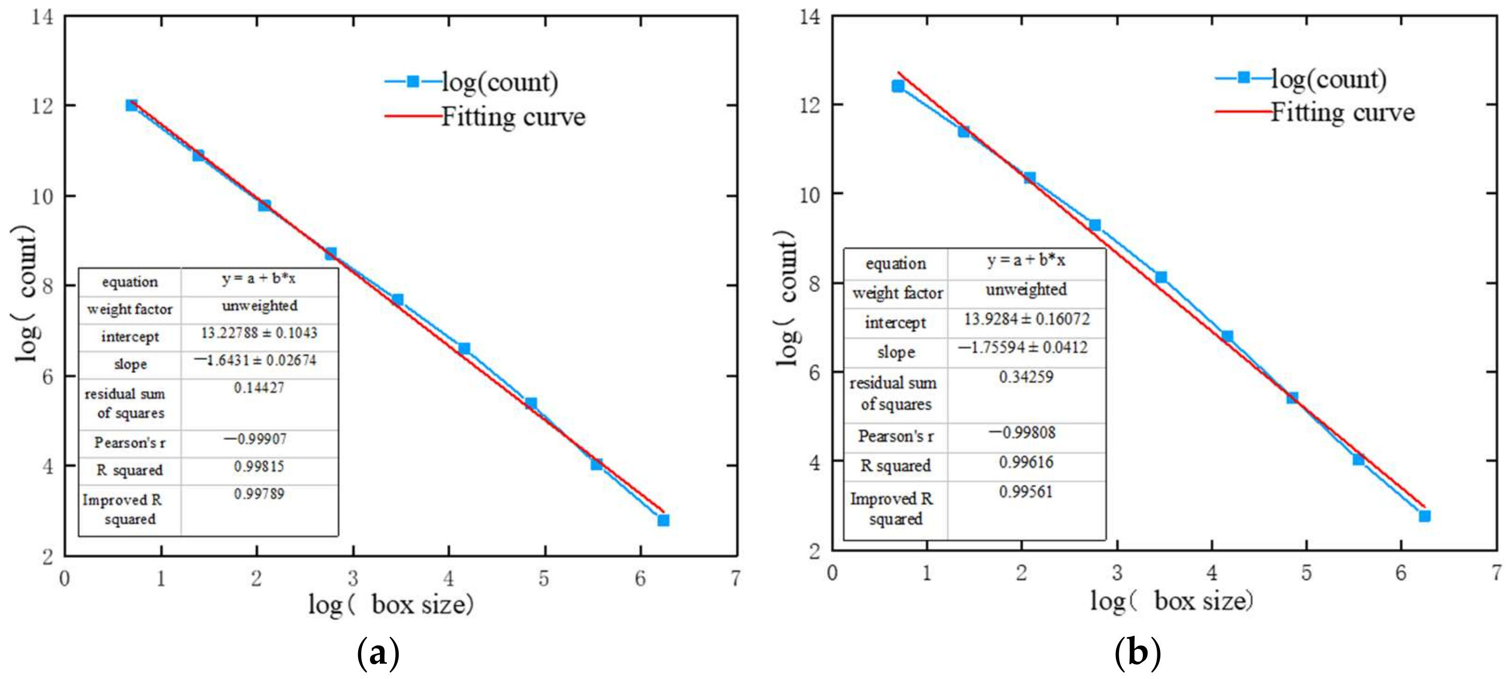
The fractal dimensions of pores in specified areas before and after the addition of pumping agent were 1.6431 and 1.7559, respectively. The increase in fractal dimension indicated that the self-similarity at the micro level was higher, the pore structure became more complicated, and the more complicated pore structure promoted the free water flow and the development of the liquid network. The enhancement of the liquid network made it possible to better promote and lubricate the migration of particles. The changes in the microstructure enabled the enhancement of the fluidity and rheological properties of the paste.

Author Contributions

Conceptualization, H.C. and J.Z.; methodology, S.W.; software, H.C. and J.Z.; validation, H.C. and J.Z. and S.W.; formal analysis, X.G.; investigation, J.L.; resources, H.C.; data curation, J.Z.; writing—original draft preparation, J.Z.; writing—review and editing, S.W.; visualization, J.L.; supervision, S.W.; project administration, H.C.; funding acquisition, H.C. All authors have read and agreed to the pblished version of the manuscript.

Funding

This research was funded by National Natural Science Foundation of China, grant number 52074137; the China Postdoctoral Science Foundation, grant number 2020T130272; the Yunnan Province Science Youth Experts Foundation, grant number 202001AU070036; the Yunnan Innovation Team, grant number 202105AE160023.

Data Availability Statement

Data sharing is not applicable.

Acknowledgments

This work was financially supported by the National Natural Science Foundation of China (52074137), the China Postdoctoral Science Foundation (2020T130272), the Yunnan Province Science Youth Experts Foundation (202001AU070036), and the Yunnan Innovation Team (202105AE160023).

Conflicts of Interest

The authors declare no conflict of interest.

References

  1. Jiao, H.; Wang, S.; Yang, Y.; Chen, X. Water recovery improvement by shearing of gravity-thickened tailings for cemented paste backfill. J. Clean. Prod. 2020, 245, 118882. [Google Scholar]
  2. Cheng, H.; Wu, S.; Li, H.; Zhang, X. Influence of time and temperature on rheology and flow performance of cemented paste backfill. Constr. Build. Mater. 2020, 231, 117117. [Google Scholar] [CrossRef]
  3. Yang, Y.; Zhao, T.; Jiao, H.; Wang, Y.; Li, H. Potential Effect of Porosity Evolution of Cemented Paste Backfill on Selective Solidification of Heavy Metal Ions. Int. J. Environ. Res. Public Health 2020, 17, 814. [Google Scholar] [CrossRef] [Green Version]
  4. Cheng, H.; Wu, S.; Zhang, X.; Wu, A. Effect of particle gradation characteristics on yield stress of cemented paste backfill. Int. J. Miner. Metall. Mater. 2020, 27, 10–17. [Google Scholar] [CrossRef]
  5. Mascaro, I.; Benvenuti, M.; Corsini, F.; Costagliola, P.; Lattanzi, P.; Parrini, P.; Tanelli, G. Mine wastes at the polymetallic deposit of Fenice Capanne (southern Tuscany, Italy). Mineralogy, geochemistry, and environmental impact. Environ. Geol. 2001, 41, 417–429. [Google Scholar]
  6. Wu, Y.Y.A.; Cheng, H.; Chen, S.; Han, Y. Status and prospects of paste technology in China. Chin. J. Eng. 2018, 40, 517–525. [Google Scholar]
  7. Henriquez, J.; Simms, P. Dynamic imaging and modelling of multilayer deposition of gold paste tailings. Miner. Eng. 2009, 22, 128–139. [Google Scholar] [CrossRef]
  8. Deschamps, T.; Benzaazoua, M.; Bussière, B.; Aubertin, M. Laboratory study of surface paste disposal for sulfidic tailings: Physical model testing. Miner. Eng. 2011, 24, 794–806. [Google Scholar] [CrossRef]
  9. Xue, Z.; Gan, D.; Zhang, Y.; Liu, Z. Rheological behavior of ultrafine-tailings cemented paste backfill in high-temperature mining conditions. Constr. Build. Mater. 2020, 253, 119212. [Google Scholar] [CrossRef]
  10. Cheng, H.; Wu, S.; Wu, A.; Cheng, W. Grading characterization and yield stress prediction based on paste stability coefficient. Chin. J. Eng. 2018, 40, 1168–1176. [Google Scholar]
  11. Lim, S.; Kim, S.; Ahn, K.; Lee, S. The effect of binders on the rheological properties and the microstructure formation of lithium-ion battery anode slurries. J. Power Sources 2015, 299, 221–230. [Google Scholar] [CrossRef]
  12. Uchikawa, H.; Sawaki, D.; Hanehara, S. Influence of kind and added timing of organic admixture on the composition, structure and property of fresh cement paste. Cem. Concr. Res. 1995, 25, 353–364. [Google Scholar] [CrossRef]
  13. Huynh, L.; Beattie, D.A.; Fornasiero, D.; Ralston, J. Effect of polyphosphate and naphthalene sulfonate formaldehyde condensate on the rheological properties of dewatered tailings and cemented paste backfill. Miner. Eng. 2006, 19, 28–36. [Google Scholar] [CrossRef]
  14. Liu, S.; Wang, H.; Wu, A.; Peng, N.; Yang, P. Study on the Rheological Properties of the Unclassified-tailings Paste Mixed with Pumping Agent. J. Wuhan Univ. Technol. 2014, 38, 919–922. [Google Scholar]
  15. Ercikdi, B.; Cihangir, F.; Kesimal, A.; Deveci, H.; Alp, I. Utilization of water-reducing admixtures in cemented paste backfill of sulphide-rich mill tailings. J. Hazard. Mater. 2010, 179, 940–946. [Google Scholar] [CrossRef]
  16. Yang, L.; Wang, H.; Wu, A.; Pan, G.; Liu, S.; Li, H. The Effect of Pumping Aid on Paste Pipeline Transportation. Metal Mine. 2014, 11, 22–26. [Google Scholar]
  17. Wu, A.; Ruan, Z.; Wang, Y.; Yin, S.; Wang, S.; Wang, Y.; Wang, J. Simulation of long-distance pipeline transportation properties of whole-tailings paste with high sliming. J. Cent. South Univ. 2018, 25, 141–150. [Google Scholar] [CrossRef]
  18. Wu, A.; Liu, X.; Wang, H.; Wang, Y.; Jiao, H.; Liu, S. Resistance characteristics of structure fluid backfilling slurry in pipeline transort. J. Cent. South Univ. 2014, 45, 4325–4330. [Google Scholar]
  19. Li, G.; Wang, H.; Wu, A.; Yang, P. Experimental study and mechanism analysis on the effect of pumping agents on the compressive strength of paste slurries. Chin. J. Eng. 2016, 38, 595–601. [Google Scholar]
  20. Zheng, J.; Gu, D. Study on influence of water-reducing agent on properties of total tailings cemented paste backfill. Nonferrous Met. 2014, 66, 60–65. [Google Scholar]
  21. Zuo, Y.; Wang, D.; Li, W.; Song, S. Review of interaction between superplasticizer and cement. Concrete 2007, 12, 79–83. [Google Scholar]
  22. Zheng, J.; Zhao, Z.; Lu, S. Effect of Superplasticizers on the Fluidity of Microfine Slurry. Met. Mine 2014, 01, 154–157. [Google Scholar]
  23. Yang, P.; Wu, A.; Wang, H.; Li, G.; Peng, N.; Chen, H. Microstructure model of paste slurry rheological properties with pumping admixture. Nonferrous Met. 2015, 67, 59–64. [Google Scholar]
  24. Wu, A.; Ai, C.; Wang, Y.; Yang, X.; Zhou, F. Test and mechanism analysis on improving rheological property of paste with pumping agent. J. Cent. South Univ. 2016, 47, 2752–2758. [Google Scholar]
  25. Zhang, L.; Wu, A.; Wang, H. Effects and mechanism of pumping agent on rheological properties of highly muddy paste. Chin. J. Eng. 2018, 40, 918–924. [Google Scholar]
  26. Hoang, Q.G.; Kaci, A.; Kadri, E.H.; Gallias, J.L. A new methodology for characterizing segregation of cement grouts during rheological tests. Constr. Build. Mater. 2015, 96, 119–126. [Google Scholar] [CrossRef]
  27. Liu, T.; Zhou, P.; Jin, M. Backfill Mining Technology and Application, 1st ed.; Metallurgical Industry Press: Beijing, China, 2001. [Google Scholar]
  28. Wu, A.X.; Jiao, H.Z.; Wang, H.J.; Li, H.; Yi, H.; Liu, X.; Liu, S. Yield stress measurements and optimization of paste tailings. J. Cent. South Univ. 2013, 44, 3371–3376. [Google Scholar]
  29. Boger, D.V. Rheology forming process. Int. J. Mech. Sci. 2009, 64, 4225–4536. [Google Scholar]
  30. Wu, A.; Li, H.; Cheng, H.; Wang, Y.; Li, C.; Ruan, Z.-E. Status and prospects of researches on rheology of paste backfill using unclassified-tailings (Part 1): Concepts, characteristics and models. Chin. J. Eng. 2020, 42, 803–813. [Google Scholar]
  31. Adeyinka, O.B.; Samiei, S.; Xu, Z.; Masliyah, J.H. Effect of particle size on the rheology of Athabasca clay suspensions. Can. J. Chem. Eng. 2009, 87, 422–434. [Google Scholar] [CrossRef]
  32. Cheng, H.; Wu, S.; Zhang, X.; Li, J. A novel prediction model of strength of paste backfill prepared from waste-unclassified tailings. Adv. Mater. Sci. Eng. 2019, 2019, 357419. [Google Scholar] [CrossRef] [Green Version]
  33. Tombácz, E.; Szekeres, M. Surface charge heterogeneity of kaolinite in aqueous suspension in comparison with montmorillonite. Appl. Clay Sci. 2006, 34, 105–124. [Google Scholar] [CrossRef]
  34. McFarlane, A.; Bremmell, K.; Addai-Mensah, J. Improved dewatering behavior of clay minerals dispersions via interfacial chemistry and particle interactions optimization. J. Colloid Interface Sci. 2006, 293, 116–127. [Google Scholar] [CrossRef] [PubMed]
  35. Cao, S.; Xue, G.; Song, W.; Teng, Q. Strain rate effect on dynamic mechanical properties and microstructure of cemented tailings composites. Constr. Build. Mater. 2020, 247, 118537. [Google Scholar] [CrossRef]
  36. Sun, W.; Hou, K.; Yang, Z.; Wen, Y. X-ray CT three-dimensional reconstruction and discrete element analysis of the cement paste backfill pore structure under uniaxial compression. Constr. Build. Mater. 2017, 138, 69–78. [Google Scholar] [CrossRef]
Figure 1. Location map of mining area.
Metals 11 01906 g001
Figure 2. Particle size distribution of unclassified tailings.
Metals 11 01906 g002
Figure 3. Schematic of slump tests: (a) size of the slump cone and (b) measurement of slump and divergence.
Metals 11 01906 g003
Figure 4. The test program.
Metals 11 01906 g004
Figure 5. Amount of slump and expansion degree with different pumping agents added.
Metals 11 01906 g005
Figure 6. Yield stress curve for different pumping agent dosages.
Metals 11 01906 g006
Figure 7. SEM image at magnification of 5000: (a) no pumping agent added; (b) pumping agent added.
Metals 11 01906 g007
Figure 8. The floc structure: (a) SEM image; (b) schematic diagram.
Metals 11 01906 g008
Figure 9. The concave structure formed after the breakage of flocs: (a) SEM image; (b) schematic diagram.
Metals 11 01906 g009
Figure 10. Particle diameter measurement: (a) diameter of typical floc structure without pumping agent; (b) particle diameter after the addition of pumping agent.
Metals 11 01906 g010
Figure 11. SEM pictures at a magnification of 1000 denoting the destructive effect of pumping agent on flocs: (a) CPB without pumping agent; (b) CPB with pumping agent.
Metals 11 01906 g011
Figure 12. Binary analysis of a microscopic image of the paste without pumping agent and the extraction process of the force chain: (a) SEM image at a magnification of 5000; (b) binary image; (c) idealized sketch of force chain.
Metals 11 01906 g012
Figure 13. Binary analysis of a microscopic image of paste with pumping agent and the extraction process of the force chain: (a) SEM image at a magnification of 5000; (b) binary image; (c) idealized sketch of force chain.
Metals 11 01906 g013
Figure 14. Quantitative analysis of boundaries between particles and pores: (a) no pumping agent added; (b) pumping agent added.
Metals 11 01906 g014
Figure 15. SEM images at 2000 magnification and binary pictures: (a) SEM without pumping agent; (b) SEM with pumping agent; (c) binary picture without pumping agent; (d) binary picture with pumping agent.
Metals 11 01906 g015
Figure 16. Distribution of pores: (a) no pumping agent added; (b) pumping agent added.
Metals 11 01906 g016
Figure 17. Calculation of fractal dimension: (a) Without pumping agent; (b) with pumping agent.
Metals 11 01906 g017
Table 1. Main chemical elements in the tailings, cement and crushed mine waste rocks.
ComponentTailings (wt.%)Crushed Mine Waste Rocks (wt.%)Cement (wt.%)
SiO236.4137.3121.5
Al2O37.773.394.5
Fe2O39.90- 12.0
CaO3.093.8663.5
MgO27.7928.154.0
SO31.63- 12.5
Others13.4110.382.0
1 “-“ indicates that the component was not measured.
Publisher’s Note: MDPI stays neutral with regard to jurisdictional claims in published maps and institutional affiliations.

