Article

Ultrasonic Welding of Nickel with Coarse and Ultrafine Grained Structures

by
Elvina R. Shayakhmetova
,
Mariya A. Murzinova
and
Ayrat A. Nazarov
*
Institute for Metals Superplasticity Problems, Russian Academy of Sciences, 39 Khalturin St., 450001 Ufa, Russia
*
Author to whom correspondence should be addressed.
Metals 2021, 11(11), 1800; https://doi.org/10.3390/met11111800
Submission received: 30 September 2021 / Revised: 2 November 2021 / Accepted: 4 November 2021 / Published: 9 November 2021

Abstract

Solid state joints of samples of coarse-grained (CG) and ultrafine-grained (UFG) nickel have been obtained for the first time using spot ultrasonic welding (USW). The UFG structure in disk-shaped samples was processed by means of high-pressure torsion (HPT). On the basis of lap shear tests, the optimal values of the clamping force resulting in the highest values of the joint strength are determined. The microstructures in the weld joints obtained at optimal parameters of USW are characterized by scanning electron microscopy. It is shown that during ultrasonic welding of coarse-grained nickel, a thin layer with an UFG microstructure is formed near the weld surfaces. The bulks of sheets retain the CG microstructure, but a significant dislocation activity is observed in these regions. During USW of samples having an UFG initial microstructure, significant grain growth occurs. Fine grains are observed only along the welding interface. An average lap shear strength of 97 MPa was obtained by welding the UFG samples, which was approximately 40% higher than the strength of samples processed by welding coarse-grained sheets (70 MPa). It is concluded that higher strength weld joints can be obtained by using sheets with the UFG structure as compared to the CG sheets.

1. Introduction

Ultrasonic welding (USW) of metals is a relatively new technology capable of joining metallic foils, thin sheets and wires [1,2,3,4,5]. Willrich [6], who carried out his experiments with ultrasonic-assisted resistant welding, was the first to demonstrate that the application of ultrasound alone could produce cold welding without any current. Since then, spot USW has developed into a mature technology, which is now widely used in electrical, automotive, medical, aerospace, and other industries [4,5].
USW is based on the use of the energy of mechanical vibrations generated in materials to be welded by a welding tool of an oscillatory system that performs reciprocating movements with an ultrasonic frequency, normally in the range of 19–25 kHz. Unlike the welding of plastics, when the vibrations occur normally to the joining interface, metals are ultrasonically welded by vibrations parallel to the interface. These vibrations cause the friction of surfaces to be welded, destruction of oxide layers, and the heating and plastic deformation of materials in the welding area followed by their bonding [4]. Moreover, the welding temperature is lower than the melting temperature of a metal, and therefore, USW of metals is a method of solid-state joining. Nevertheless, diffusion is believed to play a considerable role in the joining process too [2,5].
Ultrasonic welding is an underlying process of one the methods of additive manufacturing, ultrasonic consolidation, or ultrasonic additive manufacturing, which was recently invented by White [7]. The ultrasonic consolidation process has been applied to obtain bulk samples by seam welding of similar and dissimilar metal pairs such as Al-Al [8], Cu-Cu [9], TiAl [10,11], steel [12], etc. Ultrasonic additive manufacturing is a particularly promising technology for making composite materials by embedding different reinforcers or functional materials between metallic layers. Li and Soar [13] obtained a SiC fiber-reinforced composite with Al-alloy matrix. Chen et al. [14] designed by FEM modeling and fabricated a NiTi-Al matrix composite with a minimized coefficient of thermal expansion.
At present, joints of a satisfactory quality are normally obtained by ultrasonic welding of sheets and wires of relatively soft metals having a low hardness and yield strength, if their thickness is less than approximately 2 mm. Matheny and Graff [5] mentioned the following future directions of the studies on USW: (i) development of more powerful welding systems in order to increase the thickness of joints and weld new materials, (ii) improvement of the process control, (iii) deeper understanding of the mechanisms of welding, and (iv) development of new joint types. Obviously, the processes of microstructure evolution during welding and final mechanical characteristics of the joints processed by USW depend not only on the welding process parameters but also on the initial structure of the materials to be joined. Therefore, by the authors’ opinion, it is also important to study the role of the initial structure of materials in the process of USW and the resulting microstructures and properties of the joints.
In this regard, it is of a great interest to use ultrafine grained (UFG) sheets as materials for consolidation, since materials with the UFG structure have increased strength, hardness, and fatigue properties at room temperature [15,16]. At high temperatures, the UFG metals and alloys have an enhanced plasticity. Pressure welding of Ni-based superalloys [17] has shown that UFG alloys allow one to obtain sound diffusion bonds at significantly lower temperatures than with the same alloys in the coarse-grained state. The USW process results in a considerable, yet moderate, increase of temperature in the welding interface. Therefore, UFG metals may have better weldability during USW too.
Ultrafine grained metals and alloys can be processed by means of severe plastic deformation (SPD) methods such as high-pressure torsion (HPT) [18], equal-channel angular pressing [19], or by multiple isothermal forging (MIF) [20,21]. Sheets or foils with an UFG structure can be produced by rolling of the slabs pre-processed by MIF [22] which makes it possible to weld these materials by ultrasound and thus enables the use of UFG metals and alloys in ultrasonic additive manufacturing.
To date, there have been no studies on ultrasonic welding of metals in the UFG state. In a recent conference paper [23], we have reported preliminary results of studies on the structure and properties of ultrasonically welded joints of UFG nickel. The present paper aims at a detailed elucidation of the role of the UFG state of nickel in the evolution of its microstructure during USW, determination of the strength of the joints of UFG sheets obtained by USW, and a comparison of the results to the welding characteristics of nickel in the coarse-grained state.

2. Materials and Methods

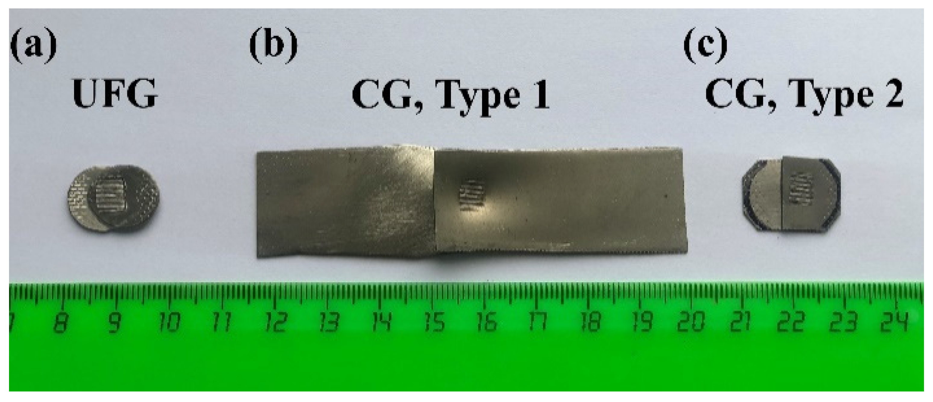
The studies were carried out using commercially pure nickel (99.5 wt.%, Grade NP2 according to the Russian classification). To obtain samples with an UFG structure, discs with the diameter of 12 mm and thickness of 1.2 mm were cut from a rod (bulk annealed billet) and subjected to HPT straining by 5 turns under a pressure of 6 GPa on a Bridgman anvil with grooves providing constrained conditions [18]. After torsion, the samples had the shape of discs with the same diameter of 12 mm and 0.7 mm thickness. As shown in [18], four turns of HPT are enough at the pressure of 6 GPa in order to obtain a fairly homogeneous microstructure in Ni discs. Moreover, when welding the UFG samples, the center of the welding tip was located approximately in the middle of their radius where the UFG microstructure is most uniform. Samples with a coarse-grained (CG) structure were cut from commercial sheets of 0.5 mm thickness. Two types of CG samples were used for welding: rectangular-shaped ones with the length of 50 mm and width of 20 mm (Type 1) and hexagonal-shaped ones with sizes about 12 mm similar to the discs with the UFG structure (Type 2). The samples of the first type were used to process joints for preliminary mechanical shear lap tests to obtain the optimal values of the clamping force during USW. The joints made from hexagonal-shaped samples were used for a final characterization of mechanical properties along with the ones obtained by welding of the UFG discs in order estimate the effect of the initial structure of nickel on the properties of joints obtained by USW.
Before welding, the surfaces of all samples were ground using 80 and 240 grit grinding papers and then washed in isopropanol and dried. USW was carried out on an experimental homemade USW setup working at a resonant frequency of 20 kHz, which was used earlier in [24] and is schematically presented in Figure 1. The amplitude of vibrations of the welding tip was set equal to 15 μm. It was measured at the end face of the welding instrument using a contactless capacity vibrometer described in [25]. A welding time of 2 s was used in all cases. The welding tip with dimensions of 4.5 mm × 6 mm having a serrated surface consisting of seven parallel teeth as schematically shown in the bottom right corner of Figure 1 oscillated parallel to the plane of the sheets. The static clamping forces (P) up to 7 kN were applied hydraulically using a resin buffer to stabilize the load.
A photographic image of the ultrasonically welded joints of Ni samples with different initial structures and shapes is presented in Figure 2.
Lap shear tests of the welded samples were carried out on an Instron 5982 universal testing machine (Instron Corp., Grove City, PA, USA) at room temperature and at constant crosshead speed of 0.5 mm/min. The samples were clamped in the wedge grips of the machine. The lap shear strength, τm, was obtained by dividing the maximum applied force of tension by the area of welding spot, i.e., 27 mm2. At least three samples were tested for the same structure, sample type, and welding conditions, and the results were averaged. Standard deviation was taken as the measurement error.
The microstructures of all samples were investigated in their cross-sections. The cross-sections of welded samples were cut parallel to the direction of vibrations of the welding instrument. The surfaces of the sections were mechanically ground and polished. The finishing treatment was carried out on a suspension with a particle size of 0.05 µm. Fractographic and structural analyses were performed by scanning electron microscopy on a TESCAN MIRA 3 LMH FEG scanning electron microscope (TESCAN ORSAY HOLDING a.s., Brno-Kohoutovice, Czech Republic) equipped with a CHANNEL 5 EBSD (electron back-scatter diffraction) analyzer (Oxford Instruments HKL, Oxford, UK). Depending on the structural state, the EBSD analysis was performed with a scanning step from 0.1 to 1 μm; two to three maps were obtained from each sample. CHANNEL 5 software (Oxford Instruments HKL, Oxford, UK) was used for processing the results of EBSD scanning. The analysis was carried out in accordance with the recommendations of [26,27]. When processing the EBSD maps, misorientations less than 2° were not taken into account; boundaries with misorientations from 2 to 15° were considered as low-angle boundaries (LABs), and boundaries with misorientations more than 15° were considered as high-angle boundaries (HABs). The high- and low-angle boundaries were plotted as black and white lines, respectively, in the crystal orientation maps (COMs). Twin boundaries were identified based on the Brandon criterion and were not highlighted in the COMs. Individual colors in the COMs corresponded to certain crystal orientations; the color-code triangles were shown in the upper right corners of the maps. The equivalent diameter was accepted as the grain size. The quantitative analysis of the microstructure was performed in accordance with the requirements of ASTM E112-10 with a confidence level of 90%.

3. Results and Discussion

3.1. Microstructures of Initial Samples

Initial microstructures of the CG and UFG samples used in the welding experiments are presented in Figure 3.
One can see that in both cases, equiaxed grains predominate in the microstructures, but the average grain sizes differ by a factor of more than 30: dav = 14.6 ± 2.1 μm (excluding twins) in the CG state and dav = 0.45 ± 0.02 μm in the UFG state. At the same time, a large fraction of the volume is occupied by grains with sizes in the range of 20–40 µm in CG samples and in the range of 0.7–1.1 µm in UFG samples (Figure 4a). Normalized distributions of grain areas/diameters are fitted to relatively narrow lognormal distributions where the largest diameter differs from the smallest one by a factor of about 10 that is typical for metals with a uniform microstructure. High angle boundaries predominate in the misorientation angle distributions (Figure 4b), and their fractions are more than 80% in both cases. However, in CG samples, about 40% of HABs are ∑3 twin boundaries, while in UFG samples, the fraction of twin misorientations is less than 3%.

3.2. Lap Shear Strength of Weld Joints

Rectangular shaped samples with the initial CG structure were welded at different clamping forces and subjected to lap shear tensile tests. These tests have shown that with an increase in the clamping force up to 7 kN, the lap shear failure load varies not monotonically. First it increases, attains the highest values of 1800–1900 N at the clamping force between 4.5 and 6 kN, and then decreases back (Figure 5a). Following these data, the effect of the initial structure on the shear strength of ultrasonically welded joints was studied at values of the clamping force P = 4.5 and 6 kN. Figure 5b shows the lap shear test results of the joints made by welding second-type (hexagonal-shaped) samples with the initial CG structure and the disc-shaped samples with the UFG structure. It is seen that the peak value of the lap shear force significantly depends on the initial microstructure of the welded samples and almost does not depend on the value of P. In both regimes of welding, the joints of UFG nickel samples are considerably stronger (the strength is higher by about 40%) than those made from the coarse-grained samples.
A comparison of Figure 5a,b shows that the shear strengths of joints of coarse-grained Ni measured using samples of different shapes are about the same. Therefore, the test results for welded discs with a diameter of 12 mm are quite reliable.
To the authors’ knowledge, only a few publications on USW of nickel and its alloys exist in the literature. Some available data from these publications are collected in Table 1. As one can see from the table, the ultimate lap shear force of nickel joints with the initial CG structure is similar to the one obtained for Inconel alloy [28,29]. The authors of Reference [28] note that “the strengths of welds in Inconel (1300–2400 N) are high and are comparable with those obtained in resistance spot welding”. As far as the samples with the initial UFG structure are concerned, their strength is similar to the highest of known values (K-Monel [29]).
Our study has shown that the strength of weld joints non-monotonically depends on the clamping force. This behavior is typical for USW and has been observed, for example, on similar Cu-Cu and dissimilar Al-Cu joints [30,31]. The increase in strength with increasing P is usually explained by an increase in the bonded area in the contact zone. A decrease in strength at high compressive forces can be associated with a significant decrease in the thickness of the sheets, especially on the periphery (along the perimeter) of the weld point, where the stress concentration is increased. The latter is true if the weld nugget pullout mode of failure is observed. In our experiments, the failure of first type CG samples occurred in the interfacial mode. The decrease of the weld strength with increasing clamping force in this case can be explained by the fact that the excess clamping load hinders the mutual displacement and friction of contacting surfaces. Local deformation in the contact zone then has a more elastic origin, the heat generation and plastic strain decrease that results in a worse bonding of the surfaces. Such an effect of the clamping force on the strength of the ultrasonically welded joints of nickel and its alloys has not been revealed before. The authors of [28,32] observed an increase in the strength of the joints with the clamping force growth that is probably a result of the narrow interval of its variation.
The presented results clearly demonstrate the effect of the UFG structure on the quality of the joints obtained by USW, which has not been studied previously. Moreover, we were unable to find any data on the effect of the initial structure of materials on the strength of joints obtained by USW. To elucidate the nature of this effect, the fracture surfaces and the structures of the samples in the welded joints are considered in the next sections.
Table 1. Values of the shear lap strength of joints of nickel and its alloys processed by spot USW.
AlloyThe Highest Tensile Shear Force, NClamping Force, kNFrequency, kHz/Amplitude, μm/Time, sSheet Thickness, mmFailure ModeReference
CP Ni UFG3000620/15/20.7Nugget pull-outThis work
CP Ni CG1998620/15/20.5Interface modeThis work
Ni 2002202.4 × 10−340/18/0.280.1Interface mode[32]
Inconel23801.320/60/1.50.47Nugget pull-out[28]
Inconel1425- 0.51-[29]
K-Monel3380- 0.51-[29]

3.3. Examination of Fracture Surfaces

The failure of weld joints processed from the samples with the initial CG structure occurred always in the interface mode, while joints of the samples with the UFG structure failed in both the interface and weld nugget pull-out modes. Most probably, this is why the results of tests of samples made from UFG sheets have a larger scatter (Figure 5b). The fracture surfaces of the joints of CG and UFG sheets (if in the latter case interfacial failure occurred) differ significantly (Figure 6 and Figure 7).
On the fracture surface of the CG sample, ridges and valleys are observed the locations of which correspond to the relief of the welding tip surface (Figure 6a). There is no such a macrorelief on the fracture surfaces of the samples with the initial UFG structure (Figure 7a). Obviously, this is related to different levels of the deformability of CG and UFG nickel at room and elevated temperatures. Most probably, the deformation of the CG sheets and formation of the macrorelief occur at the very beginning of the USW process, when the temperature is not much higher that the room one. In the further process, this relief impedes the mutual displacement of sheets, the deformation of their asperities, heating and, correspondingly, the bond formation. When the samples with the UFG structure are welded at the same conditions, the initial stage of welding does not lead to a significant plastic deformation of the sheets, since the yield stress of HPT-processed UFG nickel at room temperature is nearly three times higher than that of CG nickel [33,34]. This inhibits the formation of a microrelief on contacting surfaces unlike the case of CG samples. Due to this, in the early stages of USW, the surfaces of UFG samples are better cleaned from oxides and, most probably, are heated more intensively and their asperities are deformed better which results in the quicker formation of bonded areas and their expansion.
Higher-magnification images show that relatively smooth facets prevail on the fracture surfaces of the samples with the initial CG structure (typical area of this kind is marked as “A” in Figure 6c), and there are areas with a dimple-rupture relief (marked as “B” in Figure 6c). These facets and dimples are elongated in the direction of the tensile force (Figure 6b,c). These smooth facets differ from cleavage facets, since typical cleavage steps having different directions in adjacent grains are not observed on these surfaces. Probably, such facets appear during lap shear tensile tests when the fracture of areas with weak bonds occurs and scrubbing lines (scratches) result from the abrasion of the sheet surfaces during testing. Such lines and cracks are clearly visible on the images obtained from the peripheral zone of the joints (Figure 6d and Figure 7d). Dimples on fracture surfaces of the welded joints are usually formed during rupture of areas with strong bonds [35,36,37]. Only a dimple rupture is observed in the central zone of the fracture surfaces of the samples with the initial UFG structure (Figure 7b,c). These dimples vary in size and depth. Small dimples and lines of serpentine glide and ripples are observed on the walls of large dimples. Mentioned features are typical for metals that undergo considerable plastic deformation before rupture, and they are an indication of the high quality of the ultrasonically welded joints.

3.4. Misrostructure of Weld Joints

3.4.1. Microstructure Evolution in CG Samples during USW

Crystal orientation maps and BSE images of the zones of weld joints of sheets with the CG initial structure are presented in Figure 8. For the two values of the clamping force, there are no considerable differences in the microstructures of joints. In both cases, a layer of fine equiaxed grains with sizes up to 10 μm and a developed subgrain structure are formed near the contact surfaces of the samples welded. The width of the “fine-grained” layer varies from several micrometers to 30–50 μm, and small crystallites are present not only in the areas of good bonding but also near the pores and non-bonded regions, which are detected at microscope magnifications above 500. The grains located next to the fine-grained layer differ slightly in size from the initial ones (Figure 8 and Figure 9a). A developed LAB network has formed inside these grains. The fraction of LABs increases from 15–18% in the initial state up to 50–60%, and the fraction of twin misorientations decreases from 39–43% to 7–15% (Figure 9b). The sizes of the fragments separated by LABs vary widely from tenths to tens of microns. The highest specific length (density) of LABs is observed near the weld joint, in a layer with the width of about 150 μm. Such structural changes are typical of non-uniformly deformed metals. A fine-grained layer is formed as a result of dynamic recrystallization near the contact surface of the welded specimens, where the magnitude of deformation and temperature have the highest values [30,38]. With increasing distance from the contact surface, the strain rapidly decreases, and the processes of dynamic recovery prevail, which leads to the formation of a developed LAB network.
Microstructure development similar to that during the high-strain rate warm and hot deformation, which is accompanied by the grain refinement, can be related to intensive friction and deformation processes at the interfaces during welding. This is typical of USW of different metals and has been observed in many other studies. Yang et al. [39] found that the temperature in the welding zone during USW of 0.8 mm thick copper sheets increased to 300–450 °C depending on the welding energy, which ranged from 400 to 2400 J. At moderate energies, a fine-grained recrystallized microstructure was observed near the bond regions, while high energies resulted in large grains in the same regions. Similar microstructures with fine-grained recrystallized interface regions and original grains in the bulks were also observed by EBSD analysis by Fujii et al. [40] in Al-3003 builds made by ultrasonic consolidation. On the other hand, after ultrasonic consolidation of foils of Al alloy 3003 (150 µm thickness) and nickel alloy 201 (75 µm thickness) with original CG structures in different sequences including Al-Al, Al-Ni and Ni-Ni, the formation of UFG grains in Ni-Ni interfaces was observed only near oxide inclusions, and there were no structural changes in the zones of defect-free bonded regions [41]. It should be noted that the initial coarse-grained structure is typical for commercial sheets, and the evolution of this type of structure is very important for understanding the mechanism of joint formation.

3.4.2. Microstructure Evolution in UFG Samples during USW

The UFG structure of nickel samples is not retained after USW by the selected regimes (Figure 10 and Figure 11a). Small grains, with sizes up to 5 μm, are observed mainly near the welding interface. Grains with sizes of 15–25 μm predominate in the structure of welded specimens. Some of these grains “penetrate” into the neighbor sheet through the interface (for example, the grain in the center of Figure 10a). The results of the orientational analysis show that some HABs are “broken”, i.e., their high-angle misorientations change to small-angle ones (some of these boundaries are indicated by arrows in COMs in Figure 10a,c). As a result of this feature, the orientation maps contain abnormally large grains with an equivalent diameter of up to 80 μm, which occupy a significant fraction of the volume of the material in the joint zone (Figure 11a). All grains in the joint zone contain a developed substructure, which leads to an increase in the fraction of LABs up to 50–60% (Figure 11b).
A similar structure with a higher fraction of ∑3 twin boundaries was observed by Ghosh et al. [34] in nickel samples after HPT up to 10 revolutions under the pressure of 5 GPa at room temperature followed by annealing for 15 min at 400 °C and after HPT up to 10 revolutions at 400 °C, which can be classified as a warm severe shear deformation. Similar conditions can exist during USW too. Indeed, in the process of USW, there is a significant heating of the contact surfaces of the workpieces (the temperature can be as high as 0.8 Tm, where Tm is the melting temperature); the rate of alternating shear strain is of the order of 103 s−1, and the value of the accumulated deformation, accordingly, amounts to several thousand units. A noticeable growth of grains in nickel with an UFG structure processed by HPT or ECAP takes place upon subsequent heating above 150 °C [42,43], which is explained by the excess energy of grain boundaries [44]. An extremely high concentration of vacancies generated in this process can contribute to a faster grain growth during USW too [45]. Annealing of nickel with the original UFG structure for 1 h at 500 °C leads to anomalous grain growth (up to 140 μm) [43]. The authors of [34] explain the formation of abnormally large grains by the appearance of texture components at oblique cube orientations during HPT at temperatures of 523 and 673 K, which is not observed after HPT at 25 °C. In their opinion, thermally induced grain boundary migration favors GBs with <100>, <110> and <111> axes of misorientation. They believe that the fraction of larger recrystallized grains increases with increasing strain or strain rate.
It is likely that during USW of nickel with an initial UFG structure, grain growth occurs already at the initial stages of processing, before the appearance of bonds, when intense friction of the surfaces causes a rapid increase in temperature in the contact zone. After the formation of bonds, with an increase in the joint area, the temperature rise slows down, and the effect of high-rate alternating shear strain on the evolution of the joint structure increases. Therefore, along with grain growth, new fine grains/subgrains can form near the contacting surfaces (where the highest strain occurs).
The situation with ultrasonic welding of UFG metals described above is similar to the one with their diffusion welding. As has been shown [46], even though the exposition to a high temperature leads to the grain growth in UFG titanium alloy Ti-4Al-4V, the solid-state joints obtained by diffusion welding of samples with an initial UFG structure at temperatures of 600–800 °C possess a considerably higher strength as compared to that of the joints made by welding of coarse-grained titanium alloy at the even higher temperature of 900 °C. In other words, it is possible to obtain a compromise between the high weldability in the UFG state and the deterioration of strength properties due to the grain growth during welding. To obtain such a compromise, systematic studies should be carried out, which would involve the measurements of temperature and detailed structure and property characterization at different welding regimes. It should also be noted that “penetration” of growing grains through the welding interface similar to the phenomenon observed here (Figure 10a,c) improves the quality of joints processed by diffusion bonding of Ni-based alloys [47].
The present studies have shown that ultrasonic welding can be efficiently used to obtain sound weld joints of nickel sheets with both coarse-grained and UFG structures. Dividing the lap shear failure loads obtained in mechanical tests by the area of welding tip, one can estimate the strength of the bonds, which is equal to 70 MPa in the case of welding CG sheets and 97 MPa in the case of welding UFG sheets. Thus, the results obtained in this work show that USW of metals in an UFG state can have a good potential in improving the properties of the welds and consolidated materials. The lap shear strength of the samples processed by USW from UFG sheets are approximately 40% higher than in the case when commercial, coarse-grained sheets are welded.
Therefore, in the present work, first studies on the effect of initial UFG structure on the microstructure and properties of ultrasonically welded joints of nickel have been carried out, and it has been shown that with the welding of UFG sheets it is generally possible to consolidate materials possessing higher strength than by welding of ordinary polycrystals with coarse-grained microstructure. In the authors’ opinion, detailed studies of the regimes of USW allowing to retain the UFG structure as much as possible are needed to further explore the potential of increasing the characteristics of ultrasonically consolidated materials.

4. Conclusions

Experiments on the ultrasonic welding of nickel sheets with significantly different microstructures consisting of coarse grains with sizes in the range of tens of micrometers and ultrafine grains with sizes below one micrometer have been carried out to explore the role of the initial microstructure on the characteristics of weld joints. Microstructural changes caused by USW, lap shear strength of the joints, and fracture surfaces were studied. These studies lead to the following conclusions:
  • Sound weld joints can be obtained by welding of nickel sheets at certain regimes of spot USW. The highest strength of the joints is obtained with the used apparatus at the welding time of 2 s with clamping force in the range of 4.5 to 6 kN.
  • During ultrasonic welding of nickel with initial coarse-grained structure, grain refinement takes place near weld interfaces, and a thin layer of ultra-fine grains is formed. A developed network of sub-boundaries is formed within large grains adjacent to this layer.
  • During ultrasonic welding of samples having an UFG initial microstructure, growth of grains up to the sizes of 15–25 µm occurs, and fine grains are observed only along weld interfaces.
  • The average lap shear strength of samples made by welding of UFG sheets is about 97 MPa, which is approximately 40% higher than the strength of samples processed by welding coarse-grained sheets.
  • Fractographic studies show that a more ductile fracture occurs during lap shear tests of samples processed by welding of UFG samples. These studies suggest that the differences in the formation of weld joints of CG and UFG sheets can be related to different behaviors of the yield stress of nickel in these states: UFG Ni is significantly stronger than the CG Ni, which results in a less plastic deformation at the very beginning of the USW process, while with increasing temperature, the plasticity of UFG Ni, on the contrary, becomes higher.
  • More detailed studies of USW of UFG metals are expected to find better regimes for the process, which would limit the grain growth and simultaneously increase the bond strength and the overall strength of structures produced by the ultrasonic consolidation.

Author Contributions

Formal analysis, E.R.S. and M.A.M.; investigation, E.R.S. and M.A.M.; methodology, E.R.S. and M.A.M.; supervision, A.A.N.; writing—original draft preparation, E.R.S.; writing—review and editing, M.A.M. and A.A.N. All authors have read and agreed to the published version of the manuscript.

Funding

The present work was initially supported by the Russian Science Foundation (grant No. 16-19-10126) and finally accomplished in terms of state assignment of the Institute for Metals Superplasticity Problems of the Russian Academy of Sciences financed by the Ministry of Science and Higher Education of Russia (Registration No. AAAA-A17-117041310213-0). Electron microscopic studies and mechanical tests were carried out on the facilities of shared services center of IMSP RAS “Structural and Physical-Mechanical Studies of Materials”.

Institutional Review Board Statement

Not applicable.

Informed Consent Statement

Not applicable.

Data Availability Statement

The data presented in this study are available in the article.

Conflicts of Interest

The authors declare no conflict of interest.

References

  1. Silin, L.L.; Balandin, G.F.; Kogan, M.G. Ultrasonic Welding; Mashgiz: Moscow, Russia, 1962. (In Russian) [Google Scholar]
  2. Mitskevich, A.M. Ultrasonic welding of metals. In Physical Foundations of Ultrasonic Technology; Rosenberg, L.D., Ed.; Plenum Press: New York, NY, USA, 1973; Volume 1, Part 2; pp. 101–238. [Google Scholar]
  3. Kumar, S.; Wu, C.S.; Padhy, G.K.; Ding, W. Application of ultrasonic vibrations in welding and metal processing: A status review. J. Manuf. Processes. 2017, 26, 295–322. [Google Scholar] [CrossRef]
  4. Graff, K.F. Ultrasonic metal welding. In New Developments in Advanced Welding; Ahmed, T., Ed.; Woodhead: Cambridge, UK, 2005; pp. 241–269. [Google Scholar]
  5. Matheny, M.P.; Graff, K.F. Ultrasonic welding of metals. In Power Ultrasonics-Applications of High-Intensity Ultrasound; Gallego-Juárez, J.A., Graff, K.F., Eds.; Woodhead: Cambridge, UK, 2015; pp. 259–293. [Google Scholar]
  6. Willrich, H.O. Application of ultrasonic waves. Weld. J. 1950, 18, 61–66. [Google Scholar]
  7. White, D. Ultrasonic Object Consolidation. U.S. Patent 6,519,500, 23 March 2000. [Google Scholar]
  8. Shimizu, S.; Fujii, H.T.; Sato, Y.S.; Kokawa, H.; Sriraman, M.R.; Babu, S.S. Mechanism of weld formation during very-high-power ultrasonic additive manufacturing of Al alloy 6061. Acta Mater. 2014, 74, 234–243. [Google Scholar] [CrossRef]
  9. Sriraman, M.R.; Babu, S.S.; Short, M. Bonding characteristics during very high power ultrasonic additive manufacturing of copper. Scr. Mater. 2010, 62, 560–563. [Google Scholar] [CrossRef]
  10. Hopkins, C.D.; Dapino, M.J.; Fernandez, S.A. Statistical characterization of ultrasonic additive manufacturing Ti/Al composites. J. Eng. Mater. Technol. 2010, 132, 041006. [Google Scholar] [CrossRef]
  11. Wolcott, P.J.; Sridharan, N.; Babu, S.S.; Miriyev, A.; Frage, N.; Dapino, M.J. Characterisation of Al–Ti dissimilar material joints fabricated using ultrasonic additive manufacturing. Sci. Technol. Weld. Join. 2016, 21, 114–123. [Google Scholar] [CrossRef]
  12. Levy, A.; Miriyev, A.; Sridharan, N.; Han, T.; Tuval, E.; Babu, S.S.; Dapino, M.J.; Frage, N. Ultrasonic additive manufacturing of steel: Method, post-processing treatments and properties. J. Mater. Process. Tech. 2018, 256, 183–189. [Google Scholar] [CrossRef]
  13. Li, D.; Soar, R.C. Characterization of process for embedding SiC fibers in al 6061 o matrix through ultrasonic consolidation. J. Eng. Mater. Technol. 2009, 131, 021016. [Google Scholar] [CrossRef]
  14. Chen, X.; Hehr, A.; Dapino, M.J.; Anderson, P.M. Deformation mechanisms in NiTi-Al composites fabricated by ultrasonic additive manufacturing. Shap. Mem. Superelasticity 2015, 1, 294–309. [Google Scholar] [CrossRef]
  15. Nazarov, A.A.; Mulyukov, R.R. Nanostructured materuials. In Nanoscience, Engineering and Technology Handbook; Lyshevski, S., Brenner, D., Iafrate, J., Goddard, W., Eds.; CRC Press: Boca Raton, FL, USA, 2002; pp. 22-1–22-41. [Google Scholar]
  16. Valiev, R.Z.; Zhilyaev, A.P.; Langdon, T.G. Bulk Nanostructured Materials: Fundamentals and Applications; Wiley: Hoboken, NJ, USA, 2013. [Google Scholar] [CrossRef]
  17. Galieva, E.; Valitov, V.; Lutfullin, R.; Bikmukhametova, A. Low-temperature superplasticity of the Ni-based EK61 superalloy and application of this effect to obtain solid phase joints. Def. Diff. Forum. 2018, 385, 150–154. [Google Scholar] [CrossRef]
  18. Zhilyaev, A.P.; Langdon, T.G. Using high-pressure torsion for metal processing: Fundamentals and applications. Progr. Mater. Sci. 2008, 53, 893–979. [Google Scholar] [CrossRef]
  19. Valiev, R.Z.; Langdon, T.G. Principles of equal-channel angular pressing as a processing tool for grain refinement. Prog. Mater. Sci. 2006, 51, 881–981. [Google Scholar] [CrossRef]
  20. Mulyukov, R.R.; Imayev, R.M.; Nazarov, A.A. Production, properties and application prospects of bulk nanostructured materials. J. Mater. Sci. 2008, 43, 7257–7263. [Google Scholar] [CrossRef]
  21. Imayev, R.M.; Nazarov, A.A.; Mulyukov, R.R.; Khasanova, G.F. The principles of producing an ultrafine-grained structure in large-section billets. Lett. Mater. 2014, 4, 295–301. [Google Scholar] [CrossRef][Green Version]
  22. Valiakhmetov, O.R.; Galeyev, R.M.; Ivan’ko, V.A.; Imayev, R.M.; Inozemtsev, A.A.; Koksharov, N.L.; Kruglov, A.A.; Lutfullin, R.Y.; Mulyukov, R.R.; Nazarov, A.A.; et al. The use of nanostructured materials and nanotechnologies for the elaboration of hollow structures. Nanotechnol. Russ. 2010, 5, 108–122. [Google Scholar] [CrossRef]
  23. Shayakhmetova, E.R.; Nazarov, A.A.; Samigullina, A.A.; Zhilyaev, A.P. Ultrasonic welding of ultrafine grained nickel. IOP Conf. Ser. Mater. Sci. Eng. 2021, 1008, 012009. [Google Scholar] [CrossRef]
  24. Parkhimovich, N.Y.; Yusupova, N.R.; Nazarov, A.A. Strength of copper joints obtained by ultrasonic welding using copper intermediate layers in different structure states. Lett. Mater. 2020, 10, 322–327. [Google Scholar] [CrossRef]
  25. Contactless Vibrometer. Available online: https://cavitation.bsuir.by/en/non-contact-vibrometer (accessed on 1 November 2021).
  26. Humphreys, F. Review Grain and subgrain characterisation by electron backscatter diffraction. J. Mat. Sci. 2001, 36, 3833–3854. [Google Scholar] [CrossRef]
  27. Danilenko, V.N.; Mironov, S.; Belyakov, A.N.; Zhilyev, A.P. Application of EBSD analysis of physical materials (review). Factory Laboratory. Diagn. Mater. 2012, 2, 28–46. (In Russian) [Google Scholar]
  28. Lewis, W.J.; Antonevich, J.N.; Monroe, R.E.; Rieppel, P.J. Fundamental studies on the mechanism of ultrasonic welding. Mater. Sci. 1959. Available online: https://www.semanticscholar.org/paper/PROGRESS-REPORT-ON-RESEARCH-AND-DEVELOPMENT-OF-FOR-Lewis-Antonevich/19e4ceb12b374cb20b6ef0551b564f30fcf1e26a (accessed on 1 November 2021).
  29. Devine, J.; Welding, U. Mechanical Properties. In ASM Handbook; Welding, Brazing, and Soldering 1994; ASM International: Materials Park, OH, USA, 1994; Volume 6, pp. 907–909. [Google Scholar]
  30. Su, Z.; Zhu, Z.; Zhang, Y.; Zhang, H.; Xiao, Q. Recrystallization behavior of a pure Cu connection interface with ultrasonic welding. Metals 2021, 11, 61. [Google Scholar] [CrossRef]
  31. Ni, Z.L.; Ye, F.X. Dissimilar joining of aluminum to copper using ultrasonic welding. Mater. Manuf. Process. 2016, 31, 2091–2100. [Google Scholar] [CrossRef]
  32. Park, D.S.; Kim, J.H.; Seo, J.S. Ultrasonic Welding of Ni Thin Sheet. Int. J. Min. Metall. Mech. Eng. 2013, 1, 168–172. [Google Scholar]
  33. Zhilyaev, A.P.; Lee, S.; Nurislamova, G.V.; Valiev, R.Z.; Langdon, T.G. Microhardness and microstructural evolution in pure nickel during high-pressure torsion. Scripta Mater. 2001, 44, 2753–2758. [Google Scholar] [CrossRef]
  34. Ghosh, P.; Renk, O.; Pippan, R. Microtexture analysis of restoration mechanisms during high pressure torsion of pure nickel. Mater. Sci. Eng. A 2017, 684, 101–109. [Google Scholar] [CrossRef]
  35. Wolcott, P.J.; Dapino, M.J. Fatigue Characterization of Ultrasonic Additive Manufactured Aluminum 3003; Department of Mechanical and Aerospace Engnieering, The Ohio State University: Columbus, OH, USA, 2012. [Google Scholar]
  36. Patel, V.; Bhole, S.D.; Chen, D. Ultrasonic spot welded AZ31 magnesium alloy: Microstructure, texture, and lap shear strength. Mater. Sci. Eng. A 2013, 569, 78–85. [Google Scholar] [CrossRef]
  37. Peng, H.; Chen, D.L.; Bai, X.F.; She, X.W.; Li, D.; Jiang, X.Q. Ultrasonic spot welding of magnesium-to-aluminum alloys with a copper interlayer: Microstructural evolution and tensile properties. J. Manuf. Process. 2019, 37, 91–100. [Google Scholar] [CrossRef]
  38. Haddadi, F.; Tsivoulas, D. Grain structure, texture and mechanical property evolution of automotive aluminium sheet during high power ultrasonic welding. Mater. Charact. 2016, 118, 340–351. [Google Scholar] [CrossRef]
  39. Yang, J.; Cao, B.; Lu, Q. The effect of welding energy on the microstructural and mechanical properties of ultrasonic-welded copper joints. Materials 2017, 10, 193. [Google Scholar] [CrossRef]
  40. Fujii, H.T.; Sriraman, M.R.; Babu, S.S. Quantitative evaluation of bulk and interface microstructures in Al-3003 alloy builds made by very high power ultrasonic additive manufacturing. Metall. Mater. Trans. 2011, 42, 4045–4055. [Google Scholar] [CrossRef]
  41. Janaki Ram, G.D.; Yang, Y.; Nylander, C.; Aydelotte, B.; Stucker, B.E.; Adams, B.L. Interface Microstructures and Bond Formation in Ultrasonic Consolidation. In Proceedings of the 2007 International Solid Freeform Fabrication Symposium, Austin, TX, USA, 5 September 2007; pp. 266–283. [Google Scholar] [CrossRef]
  42. Korznikov, A.V.; Korznikova, G.F.; Myshlyaev, M.M.; Valiev, R.Z.; Salimonenko, D.; Dimitrov, O. Evolution of nanocrystalline Ni structure during heating. Phys. Met. Metall. 1997, 84, 413–417. [Google Scholar]
  43. Zhilyaev, A.P.; Nurislamova, G.V.; Valiev, R.Z.; Baró, M.D.; Langdon, T.G. Thermal stability and microstructural evolution in ultrafine-grained nickel after equal-channel angular pressing (ECAP). Metall. Mater. Trans. 2002, 33, 1865–1868. [Google Scholar] [CrossRef]
  44. Zhilyaev, A.P.; Nurislamova, G.V.; Suriñach, S.; Baró, M.D.; Langdon, T.G. Calorimetric measurements of grain growth in ultrafine-grained nickel. Mater. Phys. Mech. 2002, 5, 23–30. [Google Scholar]
  45. Chen, Y.C.; Bakavos, D.; Gholinia, A.; Prangnell, P. HAZ development and accelerated post-weld natural ageing in ultrasonic spot welding aluminium 6111-T4 automotive sheet. Acta Mater. 2012, 60, 2816–2828. [Google Scholar] [CrossRef]
  46. Lutfullin, R.Y.; Mukhametrakhimov, M.K. Effect of initial structure on the mechanical properties of specimens of titanium alloy VT6 joined in the superplastic state. Met. Sci. Heat Treat. 2006, 48, 54–56. [Google Scholar] [CrossRef]
  47. Drozdov, A.A.; Povarova, K.B.; Valitov, V.A.; Galieva, E.V.; Arginbaeva, E.G.; Bazyleva, O.A.; Bulakhtina, M.A.; Raevskikh, A.N. Effect of the Temperature of Pressure Welding of a Wrought EP975 Nickel Alloy and a Single-Crystal Intermetallic VKNA-25 Alloy on the Structure and Properties of the Welded Joints. Rus. Metall. 2020, 7, 752–759. [Google Scholar] [CrossRef]
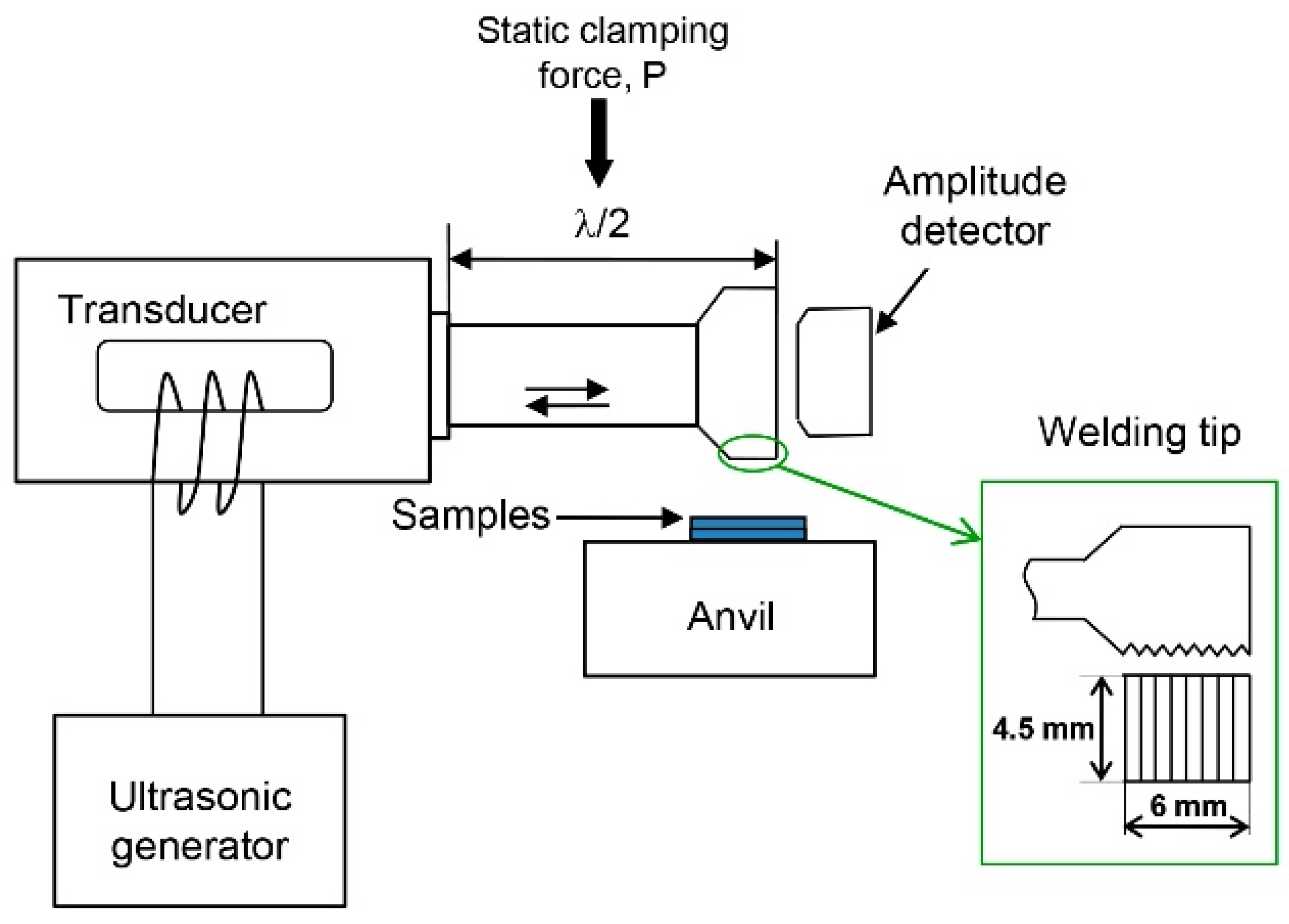
Figure 1. Schematic diagram of the ultrasonic spot welding. The static clamping force P is applied to the middle of the half-wave (λ/2) welding instrument, i.e., at the displacement node.
Metals 11 01800 g001
Figure 2. Joints of Ni samples with the initial ultrafine-grained structure (a) and Type 1 (b) and Type 2 (c) joints of samples with the initial coarse-grained structure.
Metals 11 01800 g002
Figure 3. Crystal orientation maps (a,c) and electron backscatter diffraction (EBSD) images (b,d) of the coarse-grained nickel sheet (a,b) and of HPT-processed UFG nickel (c,d) before USW.
Metals 11 01800 g003aMetals 11 01800 g003b
Figure 4. Normalized distributions of grain areas/diameters (a) and misorientation angle distributions (b) in nickel samples with the initial coarse grained and ultrafine grained structures.
Metals 11 01800 g004
Figure 5. The dependence of the lap shear strength of welds made from Type 1 CG samples on the clamping force (a) and the lap shear strengths of the USW joints made from Type 2 CG sheets and UFG discs (b).
Metals 11 01800 g005
Figure 6. Typical SEM images of lap shear fracture surfaces of coarse-grained welded samples: an overall view (a), central zone of the fracture surface (b), higher-magnification view of the area in the rectangle in (b,c), and peripheral zone of the fracture surface (d).
Metals 11 01800 g006aMetals 11 01800 g006b
Figure 7. Typical SEM images of lap shear fracture surfaces joints of samples with initial UFG structure: an overall view (a), central zone of the fracture surface (b), higher-magnification view of the area in the rectangle in (b,c), and peripheral zone of the fracture surface (d).
Metals 11 01800 g007
Figure 8. Crystal orientation maps (a,c) and BSE images (b,d) of the ultrasonically welded joints obtained under clamping forces 4.5 kN (a,b) and 6 kN (c,d) from the samples with initial CG microstructure.
Metals 11 01800 g008
Figure 9. Typical distributions of grain sizes in the original sheet and in welded joints (a) and distributions of misorientation angles in welded joints made of discs with the initial CG structure (b).
Metals 11 01800 g009
Figure 10. Crystal orientation maps (a,c) and BSE images (b,d) of ultrasonically welded joints obtained under clamping forces 4.5 kN (a,b) and 6 kN (c,d) from the samples with initial UFG microstructure.
Metals 11 01800 g010
Figure 11. Typical distributions of grain sizes in the original sheet and in weld joints (a) and distributions of misorientation angles in weld joints processed from disks with initial UFG structure at clamping loads of 4.5 and 6 kN, respectively (b).
Metals 11 01800 g011
Publisher’s Note: MDPI stays neutral with regard to jurisdictional claims in published maps and institutional affiliations.