
Copper Cathode Contamination by Nickel in Copper Electrorefining


Department of Chemical and Metallurgical Engineering, School of Chemical Engineering, Aalto University, P.O. Box 16200, FI 00076 Aalto, Finland
*
Author to whom correspondence should be addressed.
Metals 2021, 11(11), 1758; https://doi.org/10.3390/met11111758
Submission received: 24 September 2021
/
Revised: 28 October 2021
/
Accepted: 29 October 2021
/
Published: 2 November 2021
(This article belongs to the Special Issue Electrorefining in Sustainable Metals Production)
Abstract
:Nickel behavior has a significant role in the electrorefining of copper, and although it has been extensively studied from the anode and electrolyte point of view over the past decades, studies on nickel contamination at the cathode are limited. In the current paper, three possible contamination mechanisms—particle entrapment, electrolyte inclusions and co-electrodeposition—were investigated. Copper electrorefining (Cu-ER) was conducted at the laboratory scale, and the cathodes were analyzed by scanning electron microscopy with energy-dispersive X-ray spectroscopy (SEM-EDS) and flame atomic absorption spectroscopy (AAS). Particle entrapment was studied by adding NiO and Fe2O3 to the system to simulate nickel anode slime, and the experiments were replicated with industrial anode slime material. The possibility of electrolyte entrapment due to nodulation was explored through the addition of graphite to produce nodules on the cathode. Co-electrodeposition was analyzed by experiments that utilized a Hull cell. The results indicate that particle entrapment can occur at the cathode and is a major source of the nickel contamination in Cu-ER, whereas nickel compounds were not shown to promote nodulation. Inclusions of bulk electrolytes within the surface matrix were observed, proving that electrolyte entrapment is possible. As co-electrodeposition of Ni in Cu-ER is thermodynamically unlikely, these experimental results also verify that it does not occur to any significant extent.
1. Introduction
Copper electrorefining is the most common method for the production of high-purity copper cathodes. In copper electrorefining, copper metal is dissolved from a copper anode to the electrolyte and deposited on the cathode using electricity. Impurities within the copper anode either dissolve into the electrolyte or form anode slime, which settles predominantly to the bottom of the electrorefining cell. One of the typical impurities found in copper electrorefining is nickel, which mainly dissolves into the electrolyte, although it may also be found within the different compounds that form anode slimes. Due to the increased emphasis on circular economy and recycling, the concentration of nickel in anodes is expected to increase as nickel is a common alloying element used to improve the strength and corrosion resistance of copper products. Consequently, nickel concentrations can differ significantly between different refineries from approximately 80 to 27,600 µg/g on the anode and from 0.3 to 23 g/L in the electrolyte. Even within individual refineries, Ni concentrations in the anode can vary from 50–9000 µg/g and 15–19 g/L in the electrolyte [1]. In refineries that treat e-scrap, the Ni concentration of the electrolyte can rise above 30 g/L, especially when Ni is not crystallized from the bleed solution [2]. Above 3000 ppm, Ni exists primarily as NiO and kupferglimmer in the anode [3], and Adams et al. have previously classified 2000 µg/g as a high Ni concentration in the anode [4].
Earlier research of the phenomena related to nickel in the context of copper electrorefining has focused on its effects on the anode and within the electrolyte. A majority of the nickel dissolves into the electrolyte, increasing the resistivity of the electrolyte. Consequently, this increases the electricity consumption of the process [2,5]. In the anode, nickel exists primarily as NiO and kupferglimmer [3], and it has been suggested that nickel increases the porosity of the slime layer on the anode surface and causes a layered structure. This makes the passive layer less stable and less effective at slowing down the transport of electrons [6,7,8]. Nickel has not only been linked to decreased current efficiencies, but it has also been previously suggested by Tetsuka and Okamoto that the presence of nickel may cause nodulation, although the exact mechanism was not explained [9].
To date, limited research has been undertaken related to the contamination of copper cathode by nickel specifically, and the effect of nickel on the cathode side of electrorefining is not fully understood. In contrast, for other impurities, three different contamination mechanisms have been investigated. Particle entrapment on the cathode has been extensively researched [10,11,12,13,14], and it is known that floating slimes are especially detrimental to cathode quality as these entrapped particles may cause nodules on the cathode [15,16]. Severe nodulation increases the likelihood of anode–cathode pairs short-circuiting as the electrodes connect through the nodule. Moreover, despite the fact there is a general agreement that electrolyte entrapment within the cathode is possible, few investigations have been performed on the topic, and as a result, the extent of electrolyte entrapment that can occur remains unclear. Research in electrolyte entrapment has focused primarily on the adsorption of additives to the cathode [17,18]. For example, the adsorption of sulfur from the electrolyte has been studied by Brown and Hope [19], whereas Aromaa et al. noted in their nucleation study that electrolyte might be entrapped between the steel plate and copper cathode [20]. In addition, Dutrizac and Chen have found traces of leached steel blank precipitate in the microcavities located at the roots of nodules caused by anode slime clusters [21]. Co-electrodeposition of impurities on the cathode has been reported with arsenic, antimony and possibly bismuth as these elements have standard electrode potentials close to that of copper [22,23]. On the other hand, thermodynamically, nickel co-electrodeposition is extremely unlikely as this would require the copper concentration of electrolytes to be almost zero and free of bismuth, and even in this case, hydrogen evolution is likely to occur first.
The current paper aims to study and determine the role of three different mechanisms for nickel contamination in copper electrorefining. Nickel electrodeposition is investigated using a Hull cell, while electrolyte inclusions are studied with electrolysis in high Ni concentration electrolytes with additions of graphite for nodulation. Particle entrapment is investigated by performing regular electrorefining using both synthetic and two sets of industrial slimes.
2. Materials and Methods
2.1. Particle Entrapment
Three different anode slimes were used for the particle entrapment experiments: a synthetic slime and two sets of industrial anode slime. The mineralogy of the industrial anode slimes was analyzed with XRD (PANalytical X’Pert Pro MPD Alpha 1, Malvern Panalytical Ltd., Malvern, UK), and the XRD spectra were analyzed with HighScore Plus (v. 4.5, Malvern Panalytical, Malvern, UK). Elemental analysis was undertaken with ICP-OES (Perkin Elmer Optima 7100 DV, Waltham, MA, USA). The elemental composition of the industrial anode slimes is shown in Table 1, and the related XRD spectra and particle size distribution are shown in Figure 1 and Figure 2. Ni was identified to exist as Ni0.8Cu0.2O in both slimes. Both industrial slimes were also found to contain barium sulfate, lead sulfate and copper silver selenide. Copper selenide was found in slime B, whereas antimony copper and copper telluride were found in slime A. Both industrial slimes were similar in size distribution. As can be seen from Figure 2, both industrial slimes showed some agglomeration, which is indicated by the decrease at the >100 µm side of the distribution after 2 min of ultrasonication, although, overall, the slimes were of equal size.
Synthetic anode slime (SS) was composed of NiO (powder, max. 45 µm, GoodFellow Cambridge Ltd., Huntingdon, UK) and Fe2O3 (98% metal basis, −345 mesh powder, Alfa Aesar, Haverhill, MA, USA) at a ratio of 1:4. Synthetic electrolyte that contained 170 g/L (1.73 M) H2SO4, 60 g/L (0.95 M) Cu2+ and 7 g/L (0.13 M) Fe2+ was used in the experiments. Fe2+ was added to the electrolyte to increase viscosity to levels similar to those found under industrial conditions. This synthetic electrolyte was made by dissolving copper sulfate pentahydrate (technical grade, VWR Chemicals, Leuven, Belgium) and iron sulfate heptahydrate (ACS, 99+%, Alfa Aesar, Haverhill, MA, USA) to 95% sulfuric acid (technical grade, VWR chemicals, Leuven, Belgium) that had been previously diluted with ion-exchanged water.
Thin copper sheets (C310) were used as anodes, and a steel plate (AISI 304) was used as the cathode. Epoxy (Loctite Power Epoxy 5 min Universal) was used to cover the backsides of the anode and cathode to ensure that the active anode and cathode surface areas were approximately 15 cm2 (3 cm × 5 cm). A thermometer was used to monitor the electrolyte temperature, and the cell was heated with an external water bath. Magnetic stirring was used to keep the solid particles in suspension. The particle size distribution of the industrial anode slimes was analyzed using a Malvern Mastersizer 3000 (Malvern Panalytical Ltd., Malvern, UK), and the industrial anode slimes were determined to have an average particle size of about 20 µm. Cathode deposit thicknesses of 100 µm were estimated to be sufficient for significant entrapment to occur, and electrorefining times were calculated based on this desired thickness. An overview of the experimental series used for the particle entrapment studies is shown in Table 2.
Following the experiments, cathodes were rinsed with ion-exchanged water and ethanol (99.5% Altia Oyj, Rajamäki, Finland). Cathodes were then cut into three separate segments: One part was dissolved into aqua regia and analyzed for Ni content via atomic absorption spectroscopy (AAS, Thermo Fisher Scientific, Waltham, MA, USA), and Fe was also analyzed in cases with synthetic anode slime. The second section was mounted into epoxy for cross-section analysis, and the remaining part was left in an unmodified state for surface analysis. The cathode cross-sections were etched with a solution containing 28–30% ammonium hydroxide, 3% hydrogen peroxide and de-ionized water at a ratio of 5:5:1. These cathode cross-sections and the unmodified surfaces segments were analyzed with scanning electron microscopy and energy-dispersive X-ray spectroscopy (SEM-EDS, Tescan, Brno, Czech Republic).
2.2. Electrolyte Inclusions
Thin copper sheets (C310) were used as anodes, and a steel plate (AISI-304) was used as the cathode material. Epoxy (Loctite Power Epoxy 5 min Universal) was used to cover the backsides of the anode and cathode to ensure that the respective active surface areas were 6 cm2 (2 cm × 3 cm). A GillAC ACM potentiostat with a red rod reference electrode (Radiometer REF201, +199 mV vs. SHE) was used to control the applied current. The temperature of the electrolyte was monitored by a thermometer, and the cell was heated using an external water bath. Graphite powder was added to the electrolyte, such that the graphite content was 5 g/L in order to induce nodules on the cathode surfaces, and a magnetic stirrer was used to keep the graphite powder in suspension. The experimental series for the electrolyte entrapment experiments are outlined in Table 3. Synthetic electrolyte contained 40 g/L (0.63 M) Cu2+, 30 g/L (0.51 M) Ni2+ and 170 g/L (1.73 M) H2SO4 and was prepared by dissolving copper sulfate pentahydrate (technical grade, VWR Chemicals, Leuven, Belgium) and nickel sulfate hexahydrate (Baker analyzed, J.T. Baker Chemicals, Deventer, The Netherlands) into diluted sulfuric acid. Diluted sulfuric acid was made by diluting 95% sulfuric acid (technical grade, VWR Chemicals, Leuven, Belgium) with ion-exchanged water. The industrial electrolyte composition is shown in Table 4.
On completion of the experiments, cathodes were rinsed with ion-exchanged water and ethanol (99.5% Altia Oyj, Rajamäki, Finland) before being cut into three parts. One part was dissolved into aqua regia and analyzed for Ni. The second segment was sealed in epoxy for cross-section analysis, and the last section was left as is. Cross-sectional cathodes were etched with a solution containing 30% ammonium hydroxide, 3% hydrogen peroxide and de-ionized water in a ratio of 5:5:1. Cathode cross-sections and surfaces were analyzed with SEM-EDS.
2.3. Electrodeposition
A standard 250 mL Hull cell was used in the experiments. A one-millimeter thick stainless steel sheet (AISI 304) was used as the cathode material, and an LME-A grade 5 mm thick copper plate was used as the anode. The synthetic electrolyte composition for the electrodeposition experiment was the same as utilized in the electrolyte inclusion experiments. The setup was placed into a 65 °C water bath, and 1.2 A of direct current (DC) was supplied to the cell for a total of 3 h. The temperature of the electrolyte varied from 55 to 57 °C during the experiments.
The cathodes were washed with de-ionized water and ethanol (99.5% Altia Oyj, Rajamäki, Finland). Cathodes were cut into three pieces, each corresponding to a specific current density region. Selected current density ranges were 600–1900 A/m2, 420–600 A/m2 and 310–420 A/m2. Cathode pieces were then dissolved in aqua regia and analyzed for Ni with AAS (Thermo Scientific iCE 3300, Thermo Fisher Scientific, Waltham, MA, USA).
To verify the findings gained from the Hull cell investigation, high current density experiments were conducted using a regular cell design. Electrorefining was performed at 500 and 1000 A/m2 at 60 °C with GillACpotentiostat (ACM Instruments, Cark, UK) and a red rod reference electrode (Radiometer REF201, +199 mV vs. SHE). Glassy carbon was used as the cathode, and the anode was comprised of an LME-A grade copper sheet.
3. Results and Discussion
The results indicate that both particle entrapment and electrolyte inclusions can cause major contamination, which exceeds the impurity limits of cathode grades Cu-CATH-1 and Cu-CATH-2 as well as the unalloyed Cu products that are produced from Cu-CATH-1 [24]. In contrast, the co-electrodeposition of Ni in Cu electrorefining does not occur, at least to the extent that it would reduce the grading of the cathode material.
3.1. Particle Entrapment
Both the synthetic (Fe2O3 and NiO at a ratio of 4:1) and the two industrial slimes were used for the entrapment studies to determine whether certain conditions result in particle inclusion on the cathode and subsequent formation of nodules. Table 5 summarizes the observations of the particle entrapment studies. As can be seen, synthetic slime did not result in nodulation, despite the relatively high levels of Ni contamination. Overall, Fe contamination of the cathodes with synthetic slime was significantly lower than that found for Ni, with only 8–12 ppm found on some of the cathodes, cf. Ni contamination of 14–1242 ppm.
Table 5 also demonstrates that, on average, the current efficiencies achieved with synthetic slime were significantly lower when compared to that of the industrial anode slimes. Although the exact cause for this remains unknown, this phenomenon is most likely related to the nucleation of Cu. The manufacturer only guaranteed a maximum particle size of 45 µm for NiO and Fe2O3. The particle size distribution has favored the lower end of the distribution, and thus, the concentration of submicron particles has been higher than with the industrial anode slime. When combined with mixing to keep the suspension, this characteristic most likely increased the number of particle collisions occurring at potential nucleation sites compared with the SA and SB-series. For example, some Cu clusters may not have fully adhered to the cathode lattice structure prior to the collision with a particle leading to dislodgement from the surface and subsequent cluster dissolution.
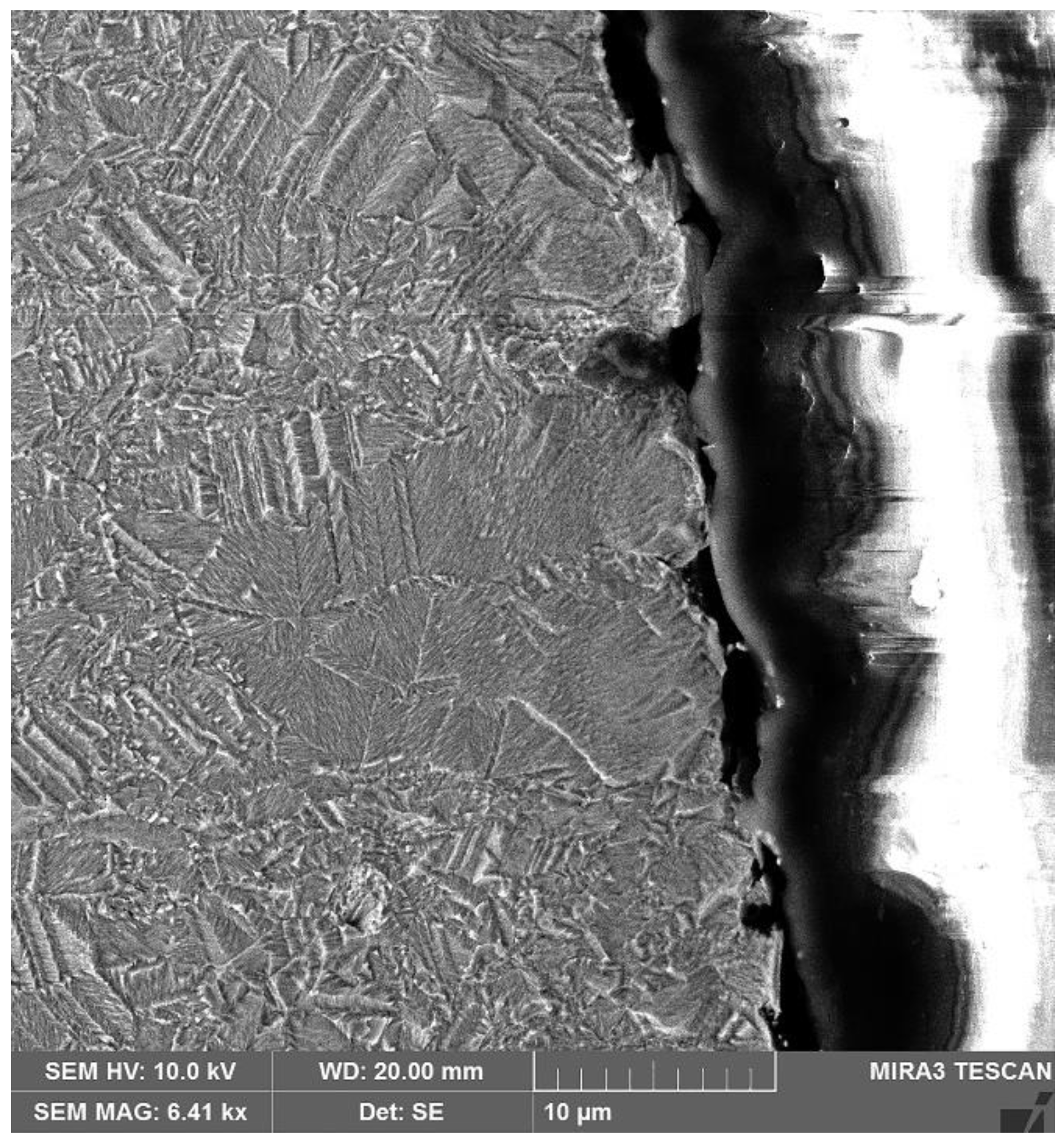
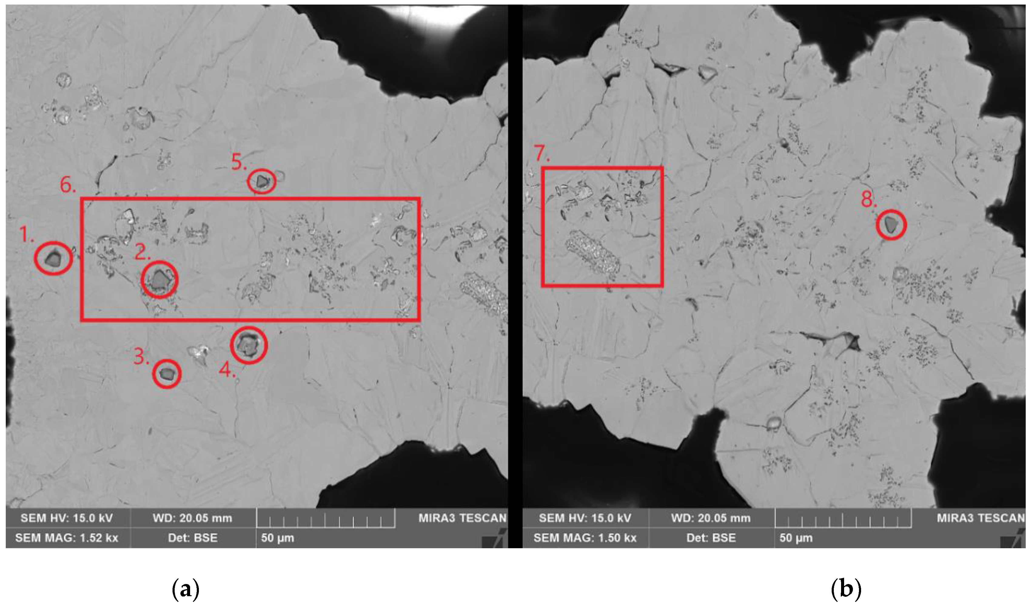
Studies of the cathode surfaces after the experiments showed that cathode surfaces are not perfectly smooth. As can be seen from Figure 3, small growth cavities of about 5 µm were found on the cathode surface, and these may provide adhesion for the entrapment of slime particles, which may, in turn, lead to nodulation. Particles found in the cathodes after experiments were typically about 10 µm or less, as can be seen in Figure 4, Figure 5 and Figure 6. Clusters of anode slime were also observed to be more abundant in nodulated regions. In addition, small pin holes were noticeable in the cathode cross-sections, and such behavior may result from anode slime dissolution due to etching or bubbles that have attached to slime clusters, as has been suggested previously [21]. Individual Ni-containing anode slime particles were found in some samples; however, these did not seem to lead to nodulation, as can be seen in Figure 4a, where the cathode surface remained smooth after particle entrapment. In contrast, a small nodule, present in Figure 4b after experiment SA-3, was found to be composed of a Cu-containing particle that adhered to the nodule root. Overall, the occurrence of nodulation appears to be dependent on the particle surface properties and conductivity. For example, the presence of the Cu-Ni-O particle—highlighted in Figure 5—results in a discernible discontinuity on the cathode surface.
The individual Cu-Ni-O particle shown in Figure 5 is probably insufficient to cause the growth of a significant nodule, which would lead to short-circuits within an industrial-scale process. Nevertheless, a significant nodule could be observed in experiment SA-5, as shown in Figure 6. In this case, clusters of anode slime were determined to be present at both the root and tip of the nodule. Even though nickel-containing particles were found to be concentrated at the nodule root, it is unclear which particle resulted in the initial nodule formation. Slimes found on the nodule also contained Fe, Se, Sn Ag and Zn (Table 6). As the presence of an individual Cu-Ni-O particle only caused a minor surface discontinuity, it is most likely that severe nodulation by a Ni-containing slime requires several particles to coalesce to form the initial nodule, thereby resulting in a positive feedback loop, where more anode slime is trapped within the nodule as it grows.
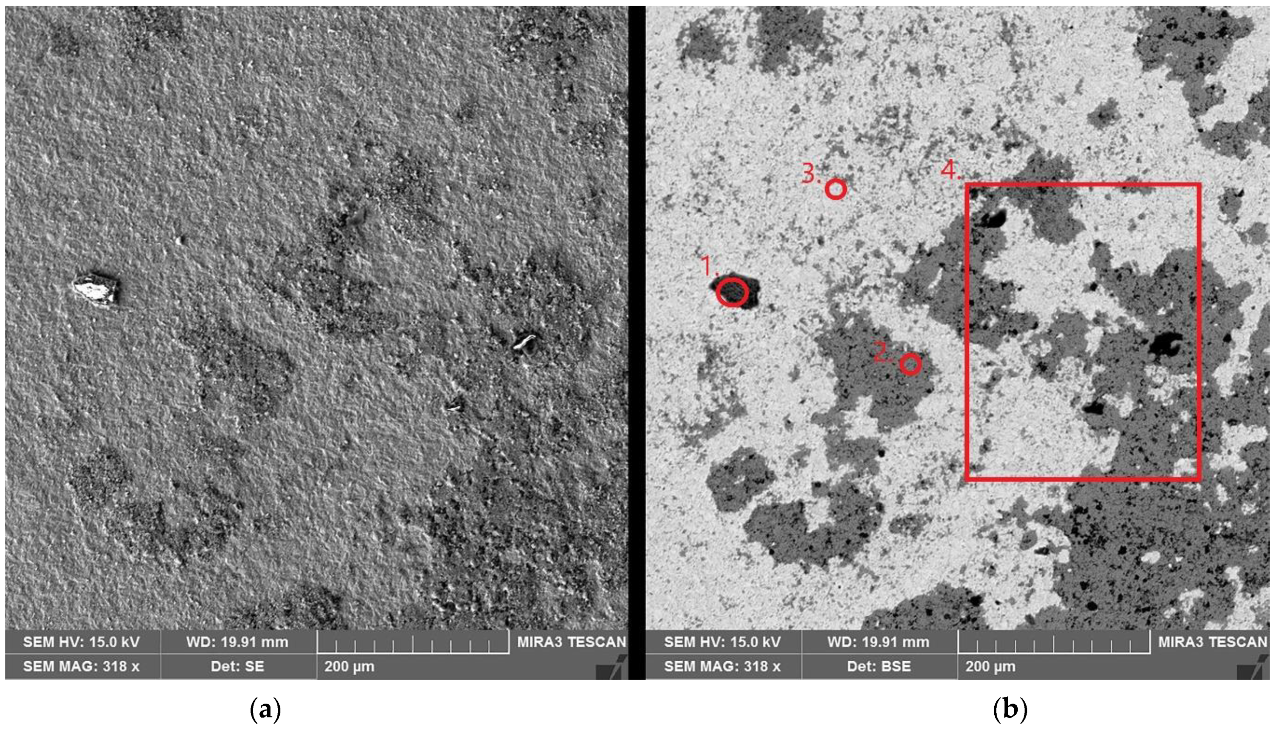
Whilst no nodulation was observed when synthetic slime was used, as can be seen from the SS-2 cathode surface micrograph presented in Figure 7, resistive particles do adhere to the cathode surface in large quantities. The related EDS results (Table 7) highlight that Fe—only present in point 1—is associated with sulfate, which indicates that the Fe contamination is due to electrolyte precipitation on the cathode rather than particle entrapment. In comparison, NiO has caused significant contamination in point 2 and area 4, although traces of NiO are found across the entire cathode surface, as highlighted by point 3, which is mostly Cu.
Ni contamination is very abundant across the whole surface, as shown by the dark gray in the BSE micrograph (Figure 7b); nonetheless, it is unclear how the presence of NiO would affect cathode growth. Given the wide area of contamination—over 100 µm in several patches—and the resistive nature of NiO, during prolonged electrorefining operations, the contamination may lead to an uneven surface as Cu deposition would favor the less resistive areas. Moreover, such an uneven morphology will, in turn, cause more anode slime to attach to the surface; however, as the NiO layer thickness is unknown, it may not be sufficient to inspire uneven cathode growth.
As can be seen from Table 5, the presence of nickel particles can result in significant contamination of the cathode. Conversely, cathode iron levels are appreciably lower (or even non-existent) than the nickel concentrations when synthetic slimes were used, despite synthetic slime being 80% Fe2O3. As the particle size of both NiO and Fe2O3 were the same, it suggests that particle surface properties have a significant role in contamination. No nodulation of cathodes was observed with synthetic slime, which supports the previous observations by Andersen et al. [25] that only conductive particles cause nodulation.
For the industrial slimes, although the SA anode slime had a lower nickel content, it resulted in markedly more contamination when compared to that observed with the SB anode slime. SA anode slimes were also shown to result in more abundant nodulation, unlike SB slime, which produced only a few observable nodules. Ni contamination increased with an increasing degree of nodulation, indicating that nickel-containing particle entrapment is mechanical in nature and does not result from electrochemical conditions.
Based on the results, it is suggested that nickel contamination is the result of cathode nodulation rather than being a root cause of such surface morphology. With real industrial slimes, the current efficiency was found to be between 90% and 100%, which is typical for industrial operations [26]. Even though the Ni and Fe levels determined in this study were considerably higher than in industrial cathodes [26], it should be noted that these results are from a small cathode, with a high degree of contamination and small surface area, whereas industrial cathode averages are determined from across the whole cathode sheet and do not correspond to localized contamination. In this case, results are more comparable to localized contamination present in industrial cathodes, i.e., nodules.
From the findings, it appears that the current density does not seem to have any effect either on the contamination by particle entrapment in the case of non-conductive particles or on the current efficiency. Nevertheless, cathodes produced at 250 A/m2 showed signs of uneven cathode growth as the lower current density results in a reduced nucleation rate [27], resulting in resistive particles having more time to attach to the steel blank and thus hindering Cu nucleation.
3.2. Electrolyte Inclusion
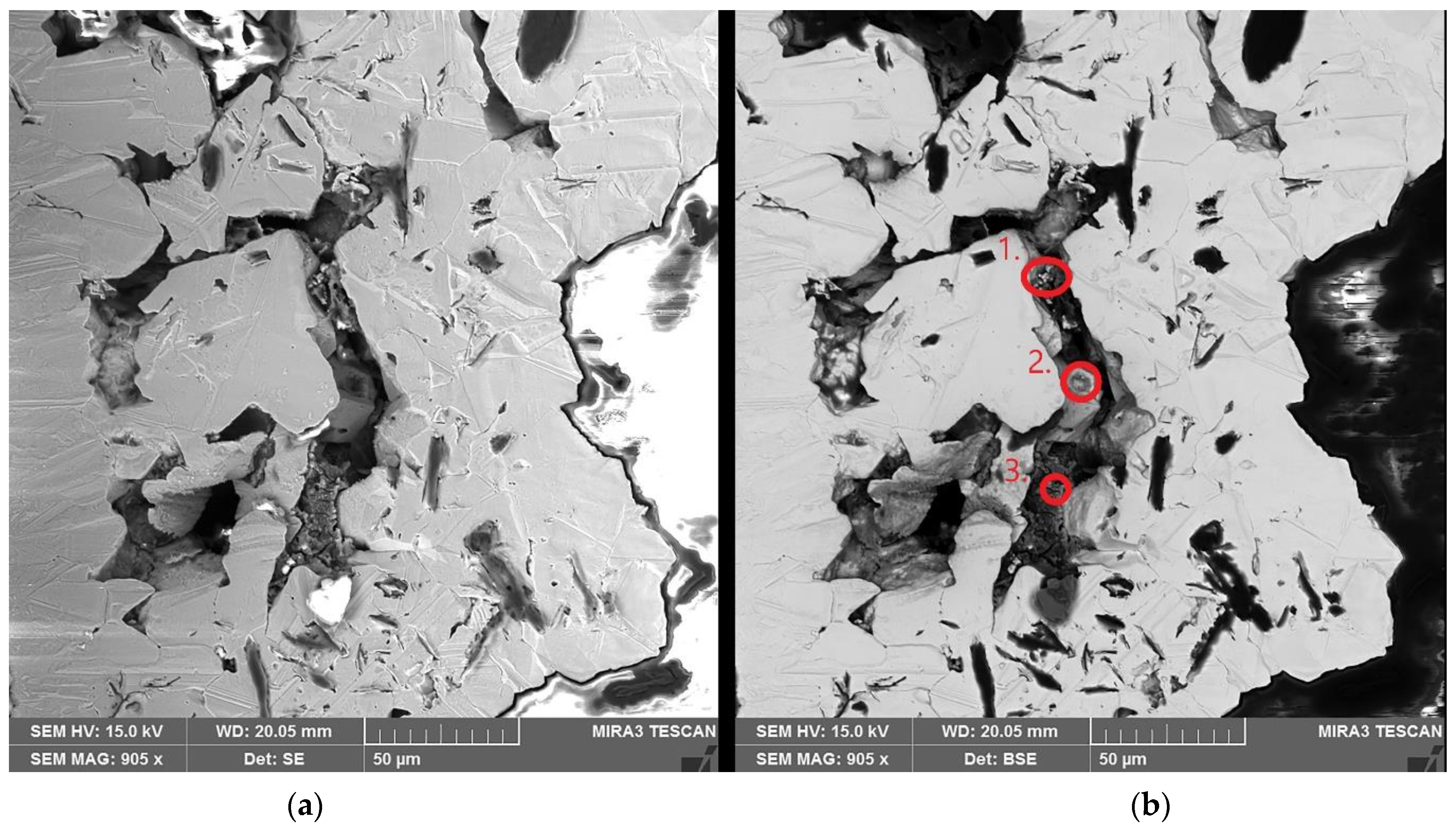
The possibility of electrolyte inclusion was studied by the addition of graphite particles, which result in nodules and create microcavities for electrolyte inclusions in the cathode. As can be seen from Figure 8, the microcavities generated can be >50 µm in size and can therefore create areas for bulk electrolyte entrapment. EDS results from the analysis points in Figure 8b are shown in Table 8. Even though a majority of the entrapped electrolyte is removed during the polishing and etching processes, the traces of nickel and sulfur indicate that electrolyte entrapment has occurred within the confines of the cavity.
The results from Table 9 demonstrate that significant electrolyte entrapment is possible with severe micro-nodulation; however, it should be noted that some of the contamination shown in Table 9 is due to precipitated electrolyte on the surface. ISS cathodes displayed a rougher surface, which is significantly harder to completely clean, and precipitation has occurred within the surface cavities.
The measured current efficiencies were similar to those previously determined under industrial conditions [26], and the IES-series, which was performed with an industrial electrolyte, had better current efficiency, probably as a result of the low-level presence of additives, such as bone glue, chloride and thiourea. These additives reduce current differences across the cathode and thus producing a smoother cathode [28]. Consequently, there are no fragile nodules that fall from the cathode due to their own weight. Current efficiency decreased with increasing current density with synthetic electrolytes, and this is probably due to the increase in the number of fragile nodules.
3.3. Electrodeposition
Based on thermodynamics, the reduction of nickel on the cathode is extremely unlikely, and the copper concentration on the cathode surface would have to be practically non-existent. Table 10 clearly demonstrates that nickel co-deposition in Cu-ER does not occur even at higher current densities. Traces of Ni on HC-1 and NiED-1 cathodes are probably due to precipitated nickel sulfate.
4. Conclusions
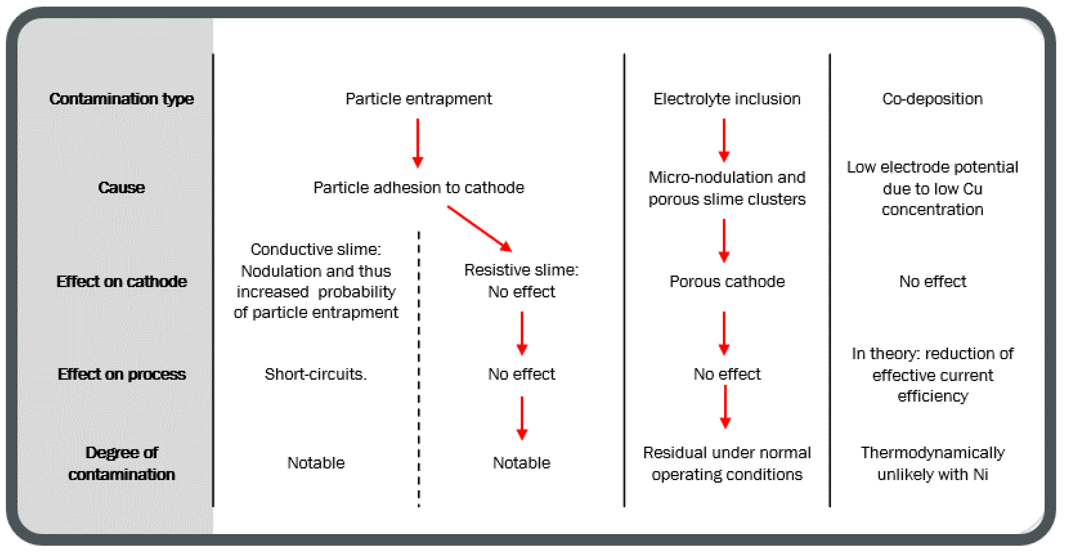
The observed contamination behavior of Ni in copper electrorefining is summarized in Figure 9. Based on the results, it can be concluded that particle entrapment is the most significant source of cathode contamination by nickel in normal electrorefining operations.
Nickel particles do not lead to cathode nodulation as was observed with synthetic anode slime, and a higher anode slime nickel concentration resulted in lower cathode Ni contamination when using industrial anode slimes. The probability of nickel contamination by particle entrapment increases due to cathode nodulation, although nodulation itself can result from improper additive levels within the electrolyte or anode slimes [10,17,21]. The presence of Ni in anode slimes alone does not appear to promote nodulation, but rather, the occurrence of nodulation is due to other elements in the particle. Furthermore, the results demonstrate that particle size is not a determining factor in nodulation, as both graphite (<45 µm) and industrial anode slimes (non-agglomerated max ≈ 100 µm) resulted in significant nodulation. Instead, the particle surface properties, such as surface charge, are likely to have a major role, as the NiO in the synthetic slime led to major cathode contamination, whereas Fe2O3 did not, despite having similar particle sizes and that Fe2O3 was more abundant within the synthetic slime.
Based on these findings, more research needs to be conducted on the effects of anode slime Ni on cathode growth. Nickel mainly exists as complex oxides in anodes, and the resistivity of these oxides will have an influence on cathode growth. For example, depending on the distribution of resistive anode slime across the cathode, an uneven surface can result from regions of preferential cathode growth. This effect may be a significant contributor to the so-called “lacy cathode growth” that can occur in the latter stages of cathode production cycles. As the anodes dissolve in CuER, the edges tend to dissolve first, resulting in an uneven current distribution on the cathodes and the consequential increase in current density enhances the nucleation rate [27] due to the decrease in cathode potential. As cathodes are switched for new steel blanks, the uneven current distribution results in Cu growth favoring the center of the cathode. With Cu nucleation further favoring the existing cathode sheet rather than the steel blank, this essentially causes local passivation of the cathode. If resistive particles settle on this steel blank after new cathodes are inserted, nucleation is likely to be further hindered.
With regard to the idea of the resistive slime layer settling on the Cu cathode surface to a significant extent, it should be noted that resistive particles do conduct electricity, so the deposition would still be possible on the slime layer. Nevertheless, the question remains as to what degree and with what type of slime composition. In such a situation, there are two scenarios:
- Cathode nodulation when slime is resistive. Anode slime particle size may determine whether slime causes a nodule or not, with larger slimes causing nodules as the base cathode growth does not reach the slime level before significant Cu deposition has occurred on the slime.
- Local passivation of the cathode. Slime is resistive enough, no Cu nucleation occurs on the slime, and the cathode starts to grow elsewhere. The authors are not aware of this phenomenon occurring in industrial operations.
Electrolyte entrapment of bulk electrolytes is possible and can lead to significant contamination of the copper cathode, but this type of contamination requires extensive micro-nodulation and the presence of numerous microcavities, which is not typical for copper electrorefining operations. Entrapped electrolyte clearly degrades the cathode product; however, from the results, no significant impacts of the entrapped electrolyte on industrial process operations could be identified. Major micro-nodulation may lead to decreased current efficiency as the deposit structure will be more fragile.
The co-electrodeposition of nickel in copper electrorefining is unlikely to occur due to associated process thermodynamics, and the analysis of the results indicates that no co-deposition occurs. It should be noted, however, that the co-deposition of Ni and Cu itself is not impossible, and nanocrystalline Ni-Cu alloys have been produced under different conditions to those used in copper electrorefining [29].
Overall, future research into the effect of nickel in producing high-purity cathodes should focus on the possible indirect effects the presence of nickel may have on cathode purity. It has been suggested that Ni affects the slime structure on the anode surface [6,7,8], and this may impact the slime settling, which, in turn, would affect particle transportation to the cathode.
Author Contributions
M.S. designed and performed the experiments and data analysis as part of his master’s thesis and performed further experiments and verifications for the paper. J.A. acted as the thesis advisor and guided practical work. M.S. and J.A. wrote the paper. M.L. reviewed the paper and provided the research funding and resources. All authors have read and agreed to the published version of the manuscript.
Funding
This research was funded by Boliden Harjavalta Oy. The APC was funded by Boliden Harjavalta Oy.
Institutional Review Board Statement
Not applicable.
Informed Consent Statement
Not applicable.
Data Availability Statement
Data regarding this article is available from the corresponding author upon a reasonable request.
Acknowledgments
This work made use of Aalto University RawMatters Facilities. Benjamin Wilson is acknowledged for his support in scientific writing.
Conflicts of Interest
The authors declare no conflict of interest. The funders had no role in the design of the study, in the collection, analyses or interpretation of data. The funders had an opportunity to review the manuscript before the publication of the results.
References
- Moats, M.S.; Robinson, T.; Davenport, W.G.; Karcas, G.; Demetrio, S. Electrolytic Copper Refining—2007 World Tankhouse Operating Data. In Proceedings of the Sixth International Copper-Cobre Conference, Toronto, ON, Canada, 25–30 August 2007; Houlachi, G.E., Edwards, J.D., Robinson, T.G., Eds.; Canadian Institute of Mining, Metallurgy and Petroleum: Montréal, QC, Canada, 2007; Volume V, pp. 195–242. [Google Scholar]
- Ikemoto, T.; Yamashita, T.; Inoue, O. Electrolytic Refining of High Ni Copper Anode at the Tankhouse in Naoshima Smelter and Refinery. In Proceedings of the 58th Annual Conference of Metallurgists (COM) Hosting the 10th Internatioanl Copper Conference 2019, Vancouver, BC, Canada, 21 August 2019. [Google Scholar]
- Chen, T.T.; Dutrizac, J.E. A Mineralogical Overview of the Behavior of Nickel during Copper Electrorefining. Metall. Trans. B 1990, 21, 229–238. [Google Scholar] [CrossRef]
- Adams, J.F.; Fossenier, J.; Shannon, J.; Sist, C. Hydrometallurgical Strategies for Higher Impurities in Copper Refining. In Proceedings of the 58th Annual Conference of Metallurgists (COM) Hosting the 10th Internatioanl Copper Conference 2019, Vancouver, BC, Canada, 21 August 2019. [Google Scholar]
- Kalliomäki, T.; Aromaa, J.; Lundström, M. Modeling the Effect of Composition and Temperature on the Conductivity of Synthetic Copper Electrorefining Electrolyte. Minerals 2016, 6, 59. [Google Scholar] [CrossRef] [Green Version]
- Jarjoura, G.; Kipouros, G.J. Cyclic Voltametric Studies of the Effect of Nickel on Copper Anode Passivation in a Copper Sulfate Solution. Can. Metall. Q. 2005, 44, 469–482. [Google Scholar] [CrossRef]
- Jarjoura, G.; Kipouros, G.J. Effect of Nickel on Copper Anode Passivation in a Copper Sulfate Solution by Electrochemical Impedance Spectroscopy. J. Appl. Electrochem. 2006, 36, 691–701. [Google Scholar] [CrossRef]
- Jarjoura, G.; Kipouros, G.J. Electrochemical Studies on the Effect of Nickel on Copper Anode Passivation in a Copper Sulphate Solution. Can. Metall. Q. 2006, 45, 283–294. [Google Scholar] [CrossRef]
- Tetsuka, D.; Okamoto, H. Effect of Antimony, Nickel and Sulfuric Acid in Copper Electrorefining. In Proceedings of the 58th Annual Conference of Metallurgists (COM) Hosting the 10th Internatioanl Copper Conference 2019, Vancouver, BC, Canada, 21 August 2019. [Google Scholar]
- Mubarok, Z.; Filzwieser, I.; Paschen, P. Analysis of Nodulated Cathodes from Atlantic Copper and New Boliden. Erzmetall 2005, 58, 203–209. [Google Scholar]
- Zeng, W.; Wang, S.; Free, M.L. Two-Phase Flow Modeling of Copper Electrorefining Involving Impurity Particles. J. Electrochem. Soc. 2017, 164, E233. [Google Scholar] [CrossRef]
- Zeng, W.; Free, M.L.; Werner, J.; Wang, S. Simulation and Validation Studies of Impurity Particle Behavior in Copper Electrorefining. J. Electrochem. Soc. 2015, 162, E338. [Google Scholar] [CrossRef] [Green Version]
- Zeng, W.; Wang, S.; Free, M.L. Experimental and Simulation Studies of Electrolyte Flow and Slime Particle Transport in a Pilot Scale Copper Electrorefining Cell. J. Electrochem. Soc. 2016, 163, E111. [Google Scholar] [CrossRef] [Green Version]
- Zeng, W.; Wang, S.; Free, M.L. Experimental Studies of the Effects of Anode Composition and Process Parameters on Anode Slime Adhesion and Cathode Copper Purity by Performing Copper Electrorefining in a Pilot-Scale Cell. Metall. Mater. Trans. B 2016, 47, 3178–3191. [Google Scholar] [CrossRef]
- Mubarok, Z.; Antrekowitsch, H.; Mori, G. Problems in the Electrolysis of Copper Anodes with High Content of Nickel, Antimony, Tin and Lead. In Proceedings of the Sixth International Copper-Cobre Conference, Toronto, ON, Canada, 25–30 August 2007; Houlachi, G.E., Edwards, J.D., Robinson, T.G., Eds.; Canadian Institute of Mining, Metallurgy and Petroleum: Montréal, QC, Canada, 2007; Volume V, pp. 59–76. [Google Scholar]
- Hiskey, J.B. Mechanism and Thermodynamics of Floating Slimes Formation. In Proceedings of the T.T. Chen Honorary Symposium on Hydrometallurgy, Electrometallurgy and Materials Characterization, Orlando, FL, USA, 11–15 March 2012; Wang, S., Dutrizac, J.E., Free, M.L., Hwang, J.Y., Kim, D., Eds.; John Wiley & Sons, Ltd.: Hoboken, NJ, USA, 2012; pp. 101–112, ISBN 978-1-118-36483-3. [Google Scholar]
- Muhlare, T.A.; Groot, D.R. The Effect of Electrolyte Additives on Cathode Surface Quality during Copper Electrorefining. J. South. Afr. Inst. Min. Metall. 2011, 111, 371–378. [Google Scholar]
- Brown, G.M.; Hope, G.A.; Schweinsberg, D.P.; Fredericks, P.M. SERS Study of the Interaction of Thiourea with a Copper Electrode in Sulphuric Acid Solution. J. Electroanal. Chem. 1995, 380, 161–166. [Google Scholar] [CrossRef]
- Brown, G.M.; Hope, G.A. In-Situ Spectroscopic Evidence for the Adsorption of SO2−4 Ions at a Copper Electrode in Sulfuric Acid Solution. J. Electroanal. Chem. 1995, 382, 179–182. [Google Scholar] [CrossRef]
- Aromaa, J.; Kekki, A.; Stefanova, A.; Forsén, O. Copper Nucleation and Growth Patterns on Stainless Steel Cathode Blanks in Copper Electrorefining. J. Solid State Electrochem. 2012, 16, 3529–3537. [Google Scholar] [CrossRef]
- Dutrizac, J.E.; Chen, T.T. Problems in the Electrolysis of Copper Anodes with High Content of Nickel, Antimony, Tin and Lead. In Proceedings of the Copper 99-Cobre 99 International Conference, Phoenix, AZ, USA, 10–13 October 1999; Dutrizac, J.E., Ramachandran, V., Eds.; The Minerals, Metals & Materials Society: Pittsburgh, PA, USA, 1999; Volume III, pp. 383–404. [Google Scholar]
- Girgis, M.; Ghali, E. Electrochemical Investigations on the Behaviour of Arsenic during Copper Electrodeposition. In The Electrorefining and Winning of Copper, Proceedings of the of the Symposium Sponsored by TMS Copper, Nickel, Cobalt, Precious Metals, and Eletrolytic Processes Committees, Held at the TMS 116th Annual Meeting, Denver, CO, USA, 24–26 February 1987; Hoffman, J.E., Bautista, R.G., Ettel, V.A., Kudryk, V., Wesely, R.J., Eds.; Metallurgical Society: Warrendale, PA, USA, 1987; pp. 173–193. [Google Scholar]
- Hiskey, J.B.; Maeda, Y. A Study of Copper Deposition in the Presence of Group-15 Elements by Cyclic Voltammetry and Auger-Electron Spectroscopy. J. Appl. Electrochem. 2003, 33, 393–401. [Google Scholar] [CrossRef]
- Finnish Standards Association SFS. CEN-TS-13388 Copper and Copper Alloys-Compendium of Compositions and Products; Finnish Standards Association SFS: Helsinki, Finland, 2013; pp. 1–70. [Google Scholar]
- Andersen, T.N.; Pitt, C.H.; Livingston, L.S. Nodulation of Electrodeposited Copper Due to Suspended Particulate. J. Appl. Electrochem. 1983, 13, 429–438. [Google Scholar] [CrossRef]
- Moats, M.S.; Filzwieser, A.; Wang, S.; Davenport, W.G.; Siegmund, A.; Robinson, T. Global Survey of Copper Electrorefining: 2019 World Tankhouse Operating Data. In Proceedings of the 58th Annual Conference of Metallurgists (COM) Hosting the 10th Internatioanl Copper Conference 2019, Vancouver, BC, Canada, 21 August 2019. [Google Scholar]
- Brande, P.V.; Winand, R. Nucleation and Initial Growth of Copper Electrodeposits under Galvanostatic Conditions. Surf. Coat. Technol. 1992, 52, 1–7. [Google Scholar] [CrossRef]
- Hiskey, J.B. The Historical Development of Electrolyte Additives and Their Specific Role and Influence on Cathode Quality. In Proceedings of the 58th Annual Conference of Metallurgists (COM) Hosting the 10th Internatioanl Copper Conference 2019, Vancouver, BC, Canada, 21 August 2019. [Google Scholar]
- Natter, H.; Schmelzer, M.; Hempelmann, R. Nanocrystalline Nickel and Nickel-Copper Alloys: Synthesis, Characterization, and Thermal Stability. J. Mater. Res. 1998, 13, 1186–1197. [Google Scholar] [CrossRef]
Figure 1.
XRD spectra of the industrial anode slimes. Major components of the slimes are marked in the spectra. In addition, slime A contains antimony copper and copper telluride, and slime B contains also copper selenide.
Figure 1.
XRD spectra of the industrial anode slimes. Major components of the slimes are marked in the spectra. In addition, slime A contains antimony copper and copper telluride, and slime B contains also copper selenide.
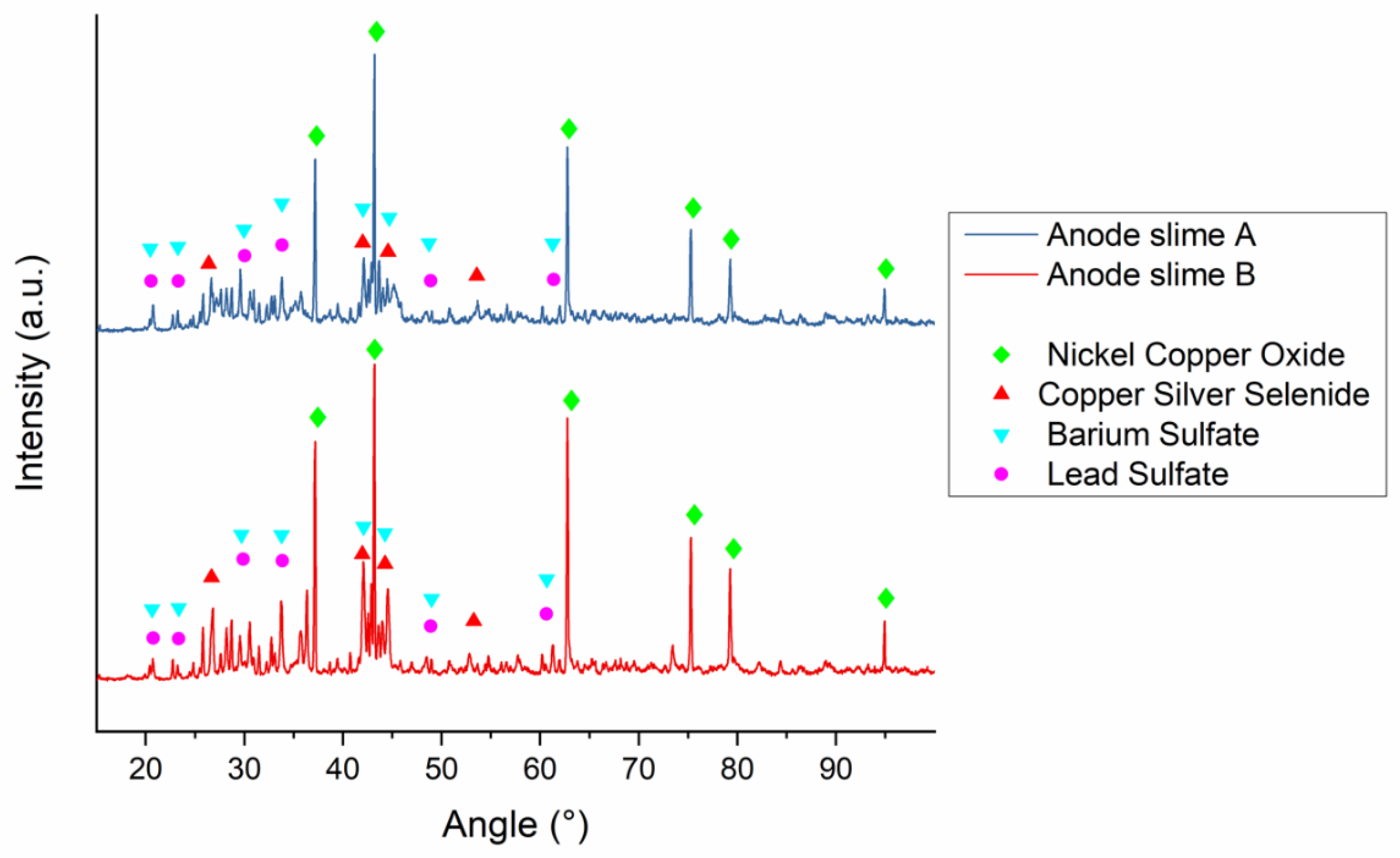
Figure 2.
Particle size distribution of the industrial anode slimes.
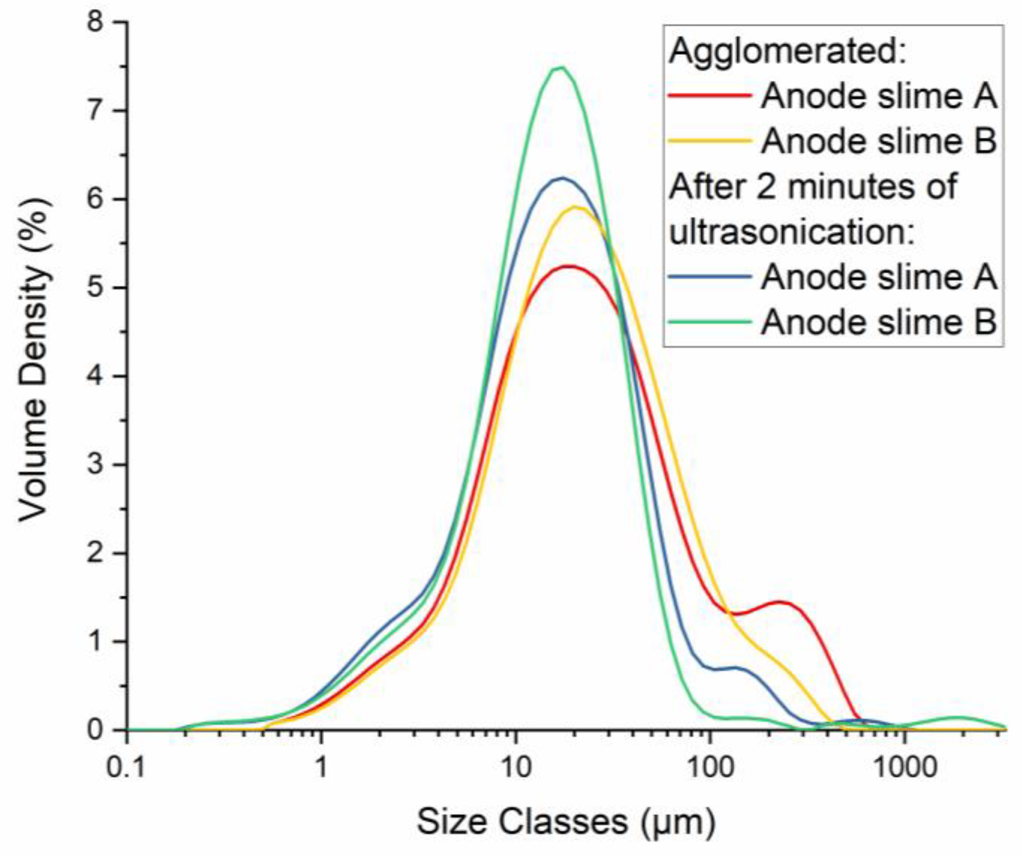
Figure 3.
Micrograph of the SS-19 cathode cross-section. No nodulation has occurred, but 5 µm ridges are visible and may act as adhesion sites for anode slime.
Figure 3.
Micrograph of the SS-19 cathode cross-section. No nodulation has occurred, but 5 µm ridges are visible and may act as adhesion sites for anode slime.

Figure 4.
BSE micrographs of SB-8 (a) and SA-3 (b) cathodes. Ni-containing anode slime was found inside the cathode without nodulation (a), and a Cu-containing particle was found at the root of a small nodule (b). The particles of interest are highlighted with a red circle.
Figure 4.
BSE micrographs of SB-8 (a) and SA-3 (b) cathodes. Ni-containing anode slime was found inside the cathode without nodulation (a), and a Cu-containing particle was found at the root of a small nodule (b). The particles of interest are highlighted with a red circle.
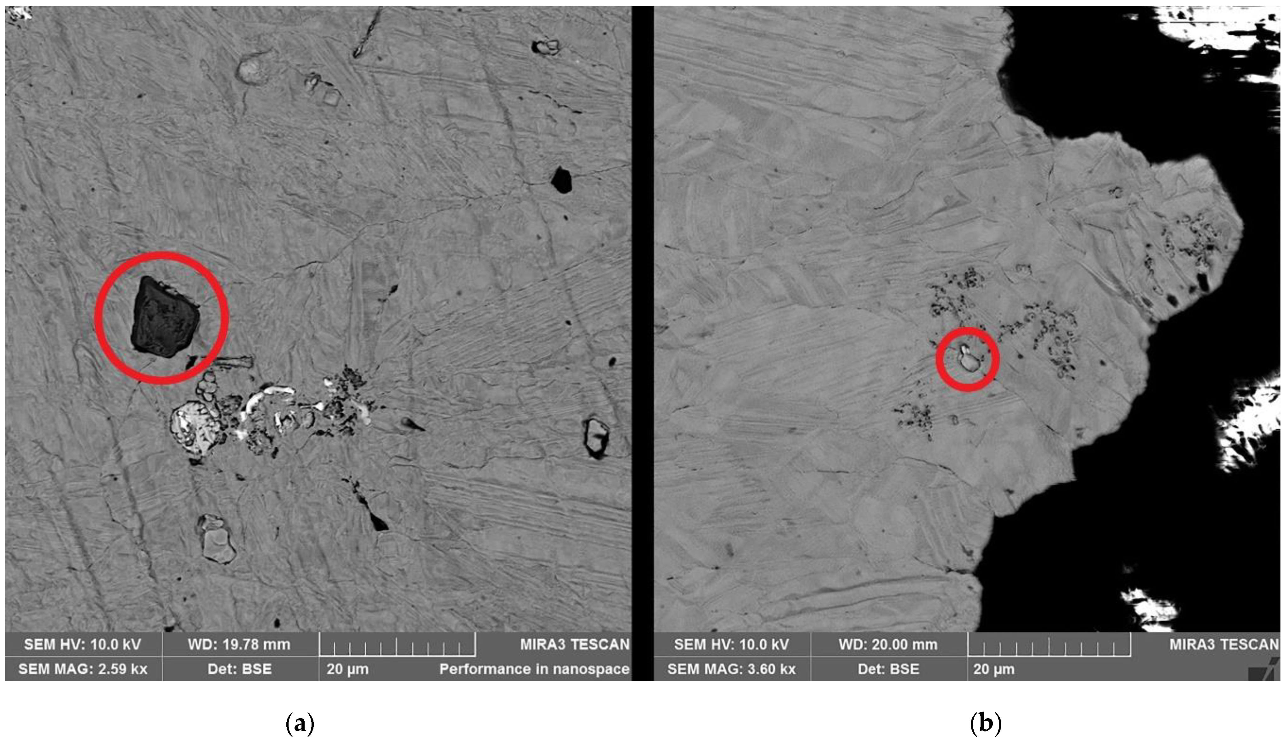
Figure 5.
Cu-Ni-O particle, highlighted with red, found at the root of a small bump on the SB-4 cathode cross-section.
Figure 5.
Cu-Ni-O particle, highlighted with red, found at the root of a small bump on the SB-4 cathode cross-section.
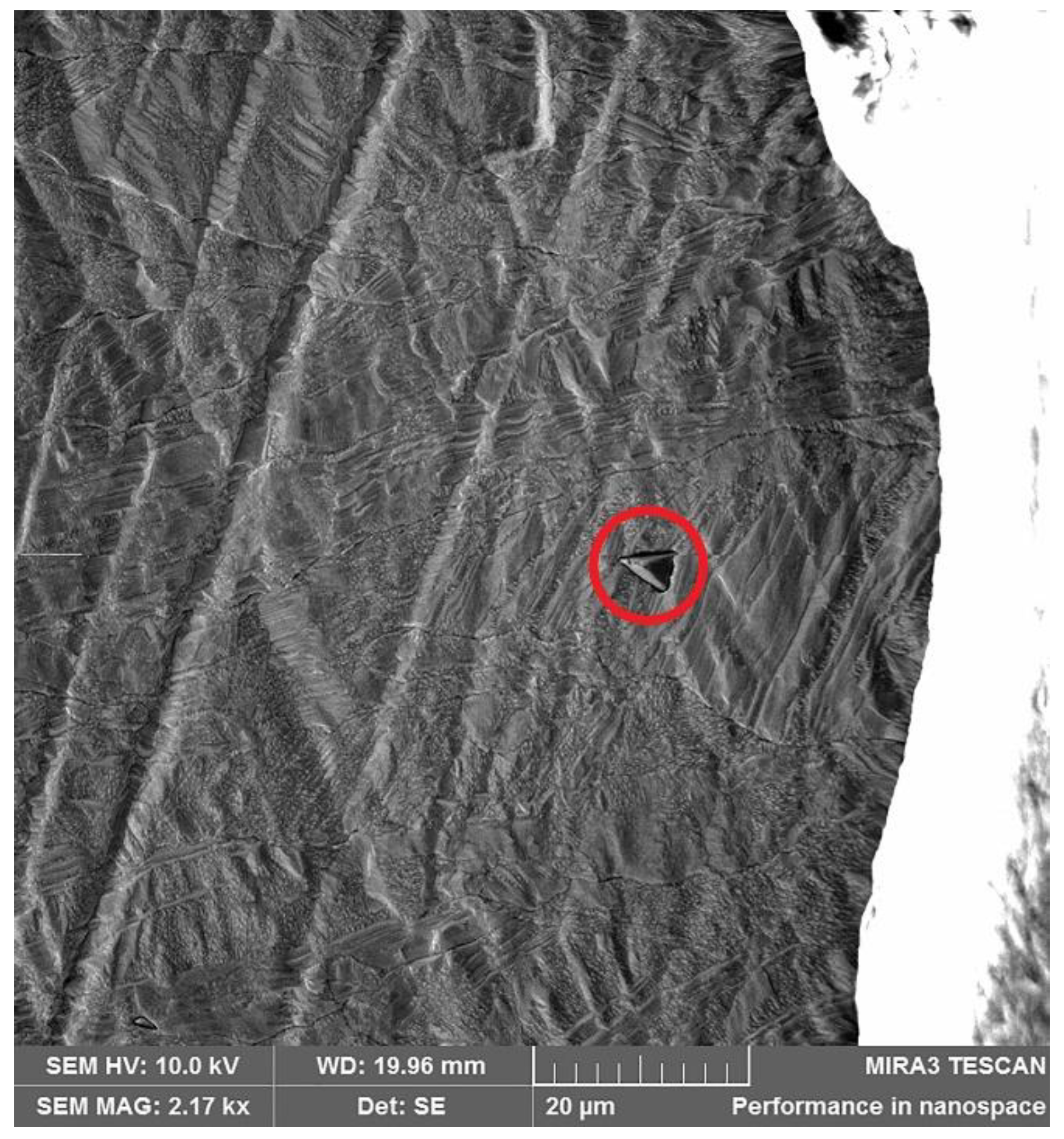
Figure 6.
Micrograph of a nodule on the cathode cross-section (SA-5). Clusters of anode slime are seen both at the root (a) and the tip (b) of the nodule. Numbers indicate the analysis points in Table 6.
Figure 6.
Micrograph of a nodule on the cathode cross-section (SA-5). Clusters of anode slime are seen both at the root (a) and the tip (b) of the nodule. Numbers indicate the analysis points in Table 6.

Figure 7.
Micrograph of the SS-2 cathode surface (a) with EDS analysis points shown on the BSE micrograph (b). Numbers indicate the analysis points in Table 7.
Figure 7.
Micrograph of the SS-2 cathode surface (a) with EDS analysis points shown on the BSE micrograph (b). Numbers indicate the analysis points in Table 7.

Figure 8.
Micrograph of the IIE-2 cathode cross-section. (a) represents the SE micrograph, and (b) is a BSE micrograph with EDS analysis points (1–3) marked. Numbers indicate the analysis points in Table 8.
Figure 8.
Micrograph of the IIE-2 cathode cross-section. (a) represents the SE micrograph, and (b) is a BSE micrograph with EDS analysis points (1–3) marked. Numbers indicate the analysis points in Table 8.

Figure 9.
Pathways for Ni contamination in copper electrorefining. Red arrows mark the observed behavior of nickel.
Figure 9.
Pathways for Ni contamination in copper electrorefining. Red arrows mark the observed behavior of nickel.


Table 1.
Composition of the industrial anode slimes.
| Element | Anode Slime A (w-%) | Anode Slime B (w-%) |
|---|---|---|
| As | 5.55 | 7.62 |
| Bi | 2.59 | 3.33 |
| Cu | 15.5 | 22 |
| Fe | 0.18 | 0.21 |
| Ni | 10.3 | 20.4 |
| Pb | 4.9 | 3.93 |
| Sb | 1.53 | 1.22 |
| Sn | 0.42 | 0.35 |
Table 2.
Experimental series used for the particle entrapment experiments. SS stands for synthetic slime. SA and SB refer to industrial anode slimes A and B.
Table 2.
Experimental series used for the particle entrapment experiments. SS stands for synthetic slime. SA and SB refer to industrial anode slimes A and B.
| Experiment | Temperature (°C) | Solid Content (g/L) | Current Density (A/m2) |
|---|---|---|---|
| SS-1 | 60 | 20 | 250 |
| SS-2 | 65 | 20 | 250 |
| SS-3 | 70 | 20 | 250 |
| SS-4 | 60 | 40 | 250 |
| SS-5 | 65 | 40 | 250 |
| SS-6 | 70 | 40 | 250 |
| SS-7 | 60 | 60 | 250 |
| SS-8 | 65 | 60 | 250 |
| SS-9 | 70 | 60 | 250 |
| SS-10 | 60 | 20 | 350 |
| SS-11 | 65 | 20 | 350 |
| SS-12 | 70 | 20 | 350 |
| SS-13 | 60 | 40 | 350 |
| SS-14 | 65 | 40 | 350 |
| SS-15 | 70 | 40 | 350 |
| SS-16 | 60 | 60 | 350 |
| SS-17 | 65 | 60 | 350 |
| SS-18 | 70 | 60 | 350 |
| SA/SB-1 | 60 | 20 | 250 |
| SA/SB-2 | 65 | 20 | 250 |
| SA/SB-3 | 70 | 20 | 250 |
| SA/SB-4 | 60 | 20 | 350 |
| SA/SB-5 | 65 | 20 | 350 |
| SA/SB-6 | 70 | 20 | 350 |
Table 3.
Experimental series for electrolyte inclusion experiments. ISS-series was conducted with synthetic electrolytes and IES-series represents the experiments with industrial electrolytes.
Table 3.
Experimental series for electrolyte inclusion experiments. ISS-series was conducted with synthetic electrolytes and IES-series represents the experiments with industrial electrolytes.
| Experiment | Temperature (°C) | Current Density (A/m2) |
|---|---|---|
| ISS-1 | 60 | 250 |
| ISS-2 | 65 | 250 |
| ISS-3 | 70 | 250 |
| ISS-4 | 60 | 300 |
| ISS-5 | 65 | 300 |
| ISS-6 | 70 | 300 |
| ISS-7 | 60 | 350 |
| ISS-8 | 65 | 350 |
| ISS-9 | 70 | 350 |
| IES-1 | 60 | 350 |
| IES-2 | 65 | 350 |
| IES-3 | 70 | 350 |
Table 4.
Elemental composition of the industrial electrolytes used in the IES-series.
| Element | Concentration |
|---|---|
| As | 12.00 g/L (160.2 mM) |
| Ba | 0.00012 g/L (0.9 µM) |
| Bi | 0.351 g/L (1.7 mM) |
| Cu | 35.80 g/L (563.37 mM) |
| Fe | 0.213 g/L (3.8 mM) |
| Ni | 18.40 g/L (313.5 mM) |
| Pb | 0.0227 g/L (0.1 mM) |
| S | 84.70 g/L (2641.5 mM) |
| Sb | 0.315 g/L (2.6 mM) |
| Sn | 0.00173 g/L (14.6 µM) |
Table 5.
Summary of the particle entrapment experiments. Ni and Fe values are concentrations in the solid cathode based on the total dissolution to aqua regia and analysis by AAS. * Solution analysis results below the detection limit (<0.2 µg/mL). Fe analysis was not performed for the SA and SB-series.
| Experiment | Current Efficiency (%) | Ni (µg/g) | Fe (µg/g) | Visual Description of Cathode Quality |
|---|---|---|---|---|
| SS-1 | 73.73 | 1242 | 12 | Smooth surface. |
| SS-2 | 65.75 | 88 | - * | No nodulation but uneven growth of cathode. |
| SS-3 | 65.05 | 148 | - * | No nodulation but uneven growth of cathode. |
| SS-4 | 72.82 | 32 | - * | No nodulation but uneven growth of cathode. |
| SS-5 | 65.18 | 14 | - * | No nodulation but uneven growth of cathode. |
| SS-6 | 60.81 | 233 | - * | No nodulation but uneven growth of cathode. |
| SS-7 | 60.45 | 183 | - * | No nodulation but uneven growth of cathode. |
| SS-8 | 63.51 | 284 | 23 | No nodulation but uneven growth of cathode. |
| SS-9 | 59.63 | 180 | - * | No nodulation but uneven growth of cathode. |
| SS-10 | NA | 309 | 8 | Smooth surface. |
| SS-11 | NA | 525 | 14 | No nodulation but NiO visible on top right section of the cathode. |
| SS-12 | 166.07 | 698 | - * | No nodulation but NiO visible on top left section of the cathode. |
| SS-13 | 103.06 | 813 | 12 | Smooth surface. |
| SS-14 | 80.06 | 1128 | - * | Smooth surface. |
| SS-15 | 78.27 | 470 | 10 | Smooth surface. |
| SS-16 | NA | 914 | - * | Smooth surface. |
| SS-17 | 75.95 | 900 | - * | Smooth surface. |
| SS-18 | 71.88 | 388 | - * | Smooth surface. |
| SA-1 | 92.81 | 137 | - | Small clusters of nodules on the right side of the cathode. |
| SA-2 | 87.94 | 118 | - | Small clusters of nodules on the right side of the cathode. |
| SA-3 | 96.92 | 29 | - | Small nodules across the cathode. |
| SA-4 | 101.14 | 368 | - | Nodules across the cathode. |
| SA-5 | 99.58 | 238 | - | Nodules across the cathode. |
| SA-6 | 109.25 | 22 | - | Few nodules on the bottom of the cathode and visible slime on the surface. |
| SB-1 | 98.20 | - * | - | Smooth surface. |
| SB-2 | 102.60 | - * | - | Smooth surface. |
| SB-3 | 103.72 | - * | - | Smooth surface. |
| SB-4 | 98.15 | 126 | - | Small nodules across the cathode. |
| SB-5 | 100.16 | 125 | - | Small clusters of nodules on the right side of the cathode. |
| SB-6 | 100.32 | - * | - | Smooth surface. |
Table 6.
EDS results from points shown in Figure 6.
Table 6.
EDS results from points shown in Figure 6.
| Point | Cu (w-%) | Ni (w-%) | Fe (w-%) | O (w-%) | Se (w-%) | Sn (w-%) | Ag (w-%) | Zn (w-%) | C (w-%) |
|---|---|---|---|---|---|---|---|---|---|
| 1 | 4.46 | 68.91 | 0.85 | 25.79 | - | - | - | - | 0.00 |
| 2 | 6.04 | 44.62 | 7.54 | 24.73 | - | 8.64 | - | 8.43 | 0.00 |
| 3 | 10.94 | 74.25 | - | 4.84 | - | - | - | - | 9.97 |
| 4 | 5.53 | 52.35 | 7.15 | 24.73 | - | 3.81 | - | 3.87 | 0.00 |
| 5 | 5.67 | 68.67 | - | 25.67 | - | - | - | - | 0.00 |
| 6 | 98.77 | - | - | 1.23 | - | - | - | - | 0.00 |
| 7 | 94.54 | - | - | 0.92 | 2.80 | - | 1.74 | - | 0.00 |
| 8 | 4.67 | 63.89 | - | 24.08 | - | - | - | - | 7.36 |
Table 7.
EDS results from the analysis points shown in Figure 7b. No carbon was used in the experiment, but the traces detected by the EDS are from the chamber atmosphere as carbon is commonly sputtered on poorly conductive samples.
Table 7.
EDS results from the analysis points shown in Figure 7b. No carbon was used in the experiment, but the traces detected by the EDS are from the chamber atmosphere as carbon is commonly sputtered on poorly conductive samples.
| Point # | Cu (w-%) | Ni (w-%) | Fe (w-%) | O (w-%) | S (w-%) | C (w-%) |
|---|---|---|---|---|---|---|
| 1 | 37.85 | - | 3.05 | 38.48 | 18.98 | 1.60 |
| 2 | 3.32 | 73.88 | - | 21.56 | 0.15 | 0 |
| 3 | 96.42 | 1.77 | - | 1.34 | - | 0.42 |
| 4 | 48.76 | 32.64 | - | 15.92 | 0.20 | 1.26 |
Table 8.
EDS analysis results from points shown in Figure 8b. Traces of carbon are from graphite but also from the SEM chamber, as carbon is a common coating material for poorly conductive samples.
Table 8.
EDS analysis results from points shown in Figure 8b. Traces of carbon are from graphite but also from the SEM chamber, as carbon is a common coating material for poorly conductive samples.
| Point | C (w-%) | Cu (w-%) | Ni (w-%) | S (w-%) | O (w-%) |
|---|---|---|---|---|---|
| 1 | 4.93 | 86.35 | - | - | 4.18 |
| 2 | 0.57 | 98.27 | - | 0.07 | 1.09 |
| 3 | 17.11 | 43.30 | 2.72 | 4.31 | 31.87 |
Table 9.
Summary of the electrolyte inclusion experiments. Ni concentration in the solid cathode, based on total dissolution to aqua regia and analysis by flame-AAS.
Table 9.
Summary of the electrolyte inclusion experiments. Ni concentration in the solid cathode, based on total dissolution to aqua regia and analysis by flame-AAS.
| Experiment | Current Efficiency (%) | Ni (µg/g) |
|---|---|---|
| ISS-1 | 95.3 | 43 |
| ISS-2 | 98.7 | 69 |
| ISS-3 | 95.7 | 271 |
| ISS-4 | 100.7 | 130 |
| ISS-5 | 93.4 | 152 |
| ISS-6 | 90.7 | 330 |
| ISS-7 | 76.6 | 80 |
| ISS-8 | 85.3 | 206 |
| ISS-9 | 99.9 | 72 |
| IES-1 | 99.0 | 51 |
| IES-2 | 100.9 | 81 |
| IES-3 | 101.1 | 72 |
Table 10.
Summary of Ni co-electrodeposition experiments. Ni concentration in the solid cathode, based on total dissolution to aqua regia and analysis by flame-AAS. * Solution analysis results below the detection limit (<0.2 µg/mL).
Table 10.
Summary of Ni co-electrodeposition experiments. Ni concentration in the solid cathode, based on total dissolution to aqua regia and analysis by flame-AAS. * Solution analysis results below the detection limit (<0.2 µg/mL).
| Experiment | Current Density Region (A/m2) | Ni (µg/mg) |
|---|---|---|
| HC-1 | 600–1900 | 12 |
| 420–600 | 8 | |
| 310–420 | 18 | |
| HC-2 | 600–1900 | - * |
| 420–600 | - * | |
| 310–420 | - * | |
| HC-3 | 600–1900 | - * |
| 420–600 | - * | |
| 310–420 | - * | |
| NiED-1 | 1000 | 40 |
| NiED-2 | 1000 | - * |
| NiED-3 | 1000 | - * |
| NiED-4 | 500 | - * |
| NiED-5 | 500 | - * |
| NiED-6 | 500 | - * |
Publisher’s Note: MDPI stays neutral with regard to jurisdictional claims in published maps and institutional affiliations. |
© 2021 by the authors. Licensee MDPI, Basel, Switzerland. This article is an open access article distributed under the terms and conditions of the Creative Commons Attribution (CC BY) license (https://creativecommons.org/licenses/by/4.0/).
Share and Cite
MDPI and ACS Style
Sahlman, M.; Aromaa, J.; Lundström, M. Copper Cathode Contamination by Nickel in Copper Electrorefining. Metals 2021, 11, 1758. https://doi.org/10.3390/met11111758
AMA Style
Sahlman M, Aromaa J, Lundström M. Copper Cathode Contamination by Nickel in Copper Electrorefining. Metals. 2021; 11(11):1758. https://doi.org/10.3390/met11111758
Chicago/Turabian StyleSahlman, Mika, Jari Aromaa, and Mari Lundström. 2021. "Copper Cathode Contamination by Nickel in Copper Electrorefining" Metals 11, no. 11: 1758. https://doi.org/10.3390/met11111758
Note that from the first issue of 2016, this journal uses article numbers instead of page numbers. See further details here.