
Study on the Hot Cracking Law of Inconel 690/52M Welding Material on F304LN Base Metal by Multi-Layer Cladding

Abstract
:1. Introduction
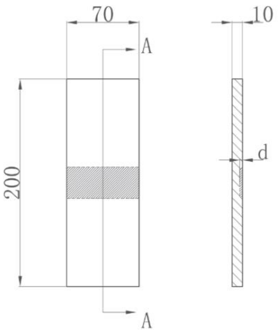
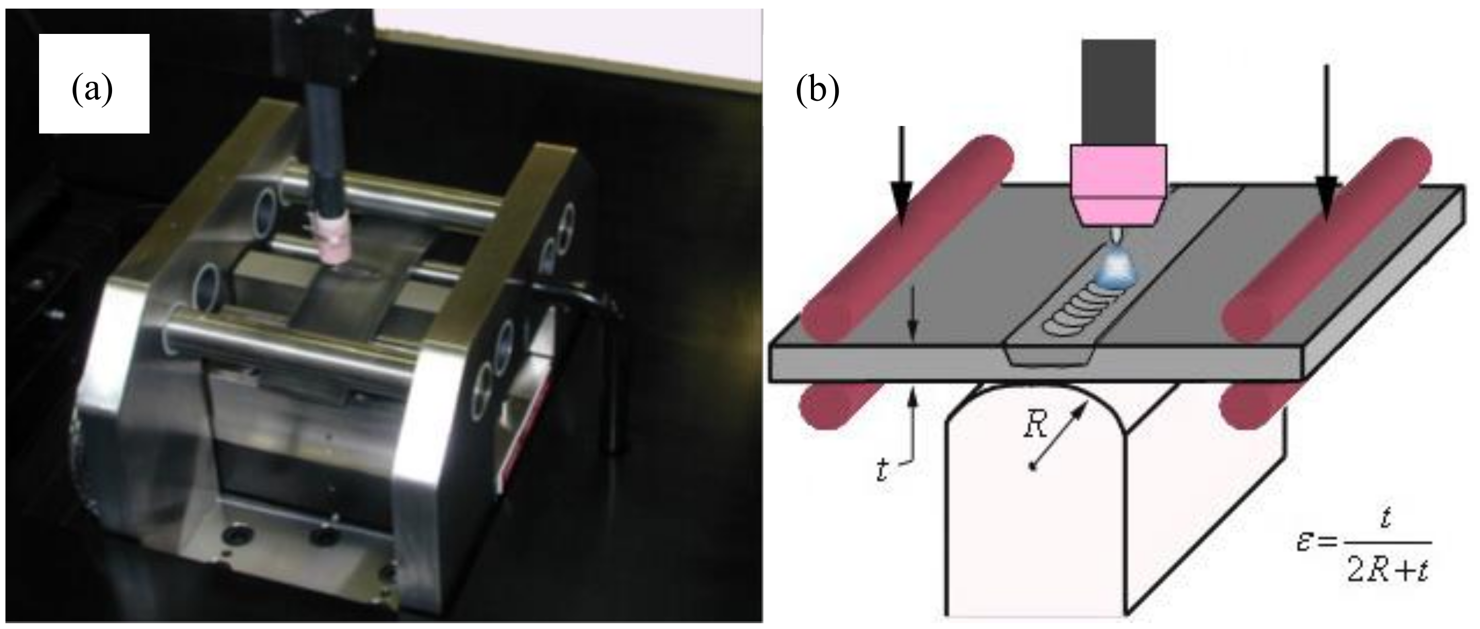
2. Materials and Methods
3. Results
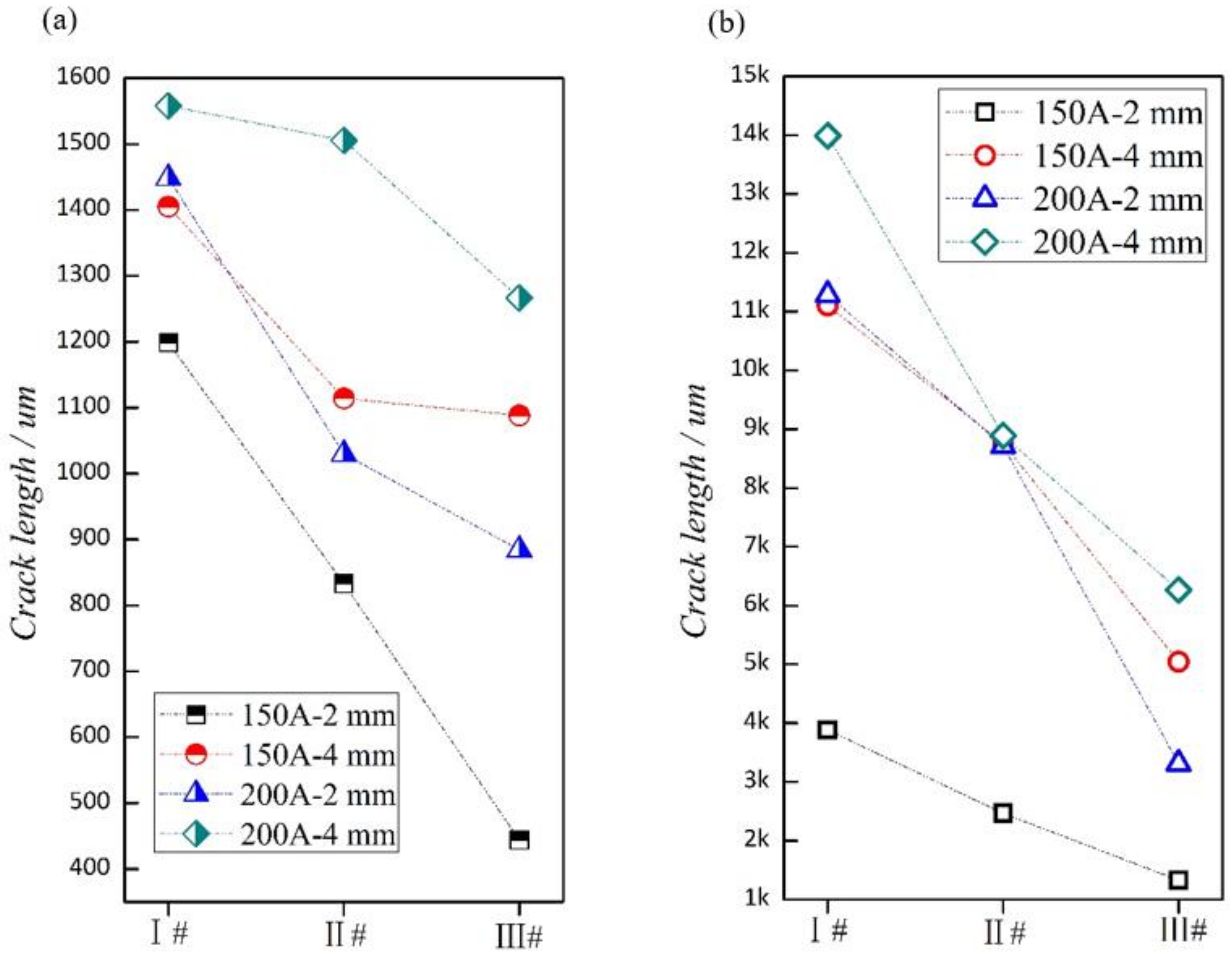
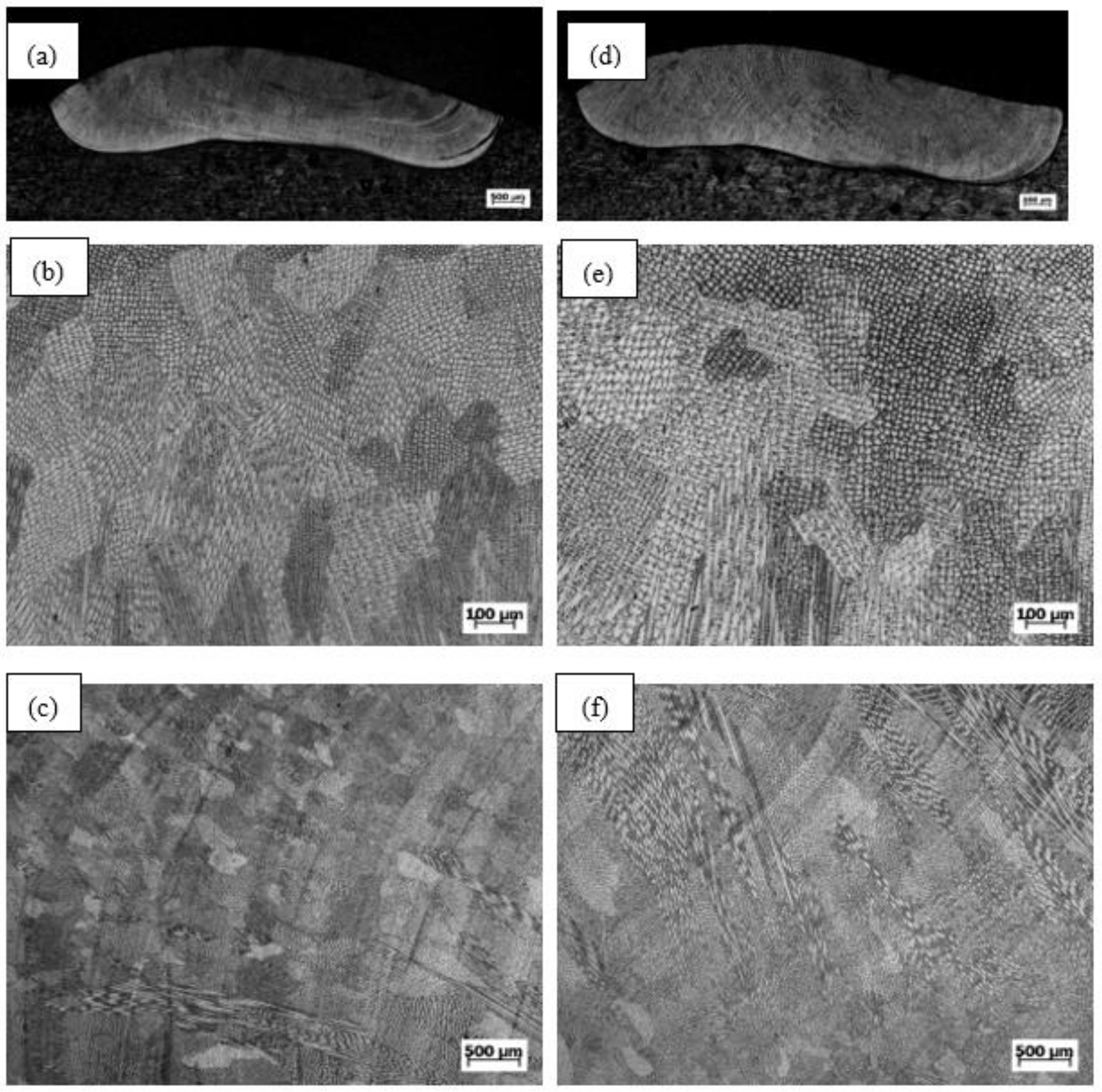
3.1. Varestraint Test Results
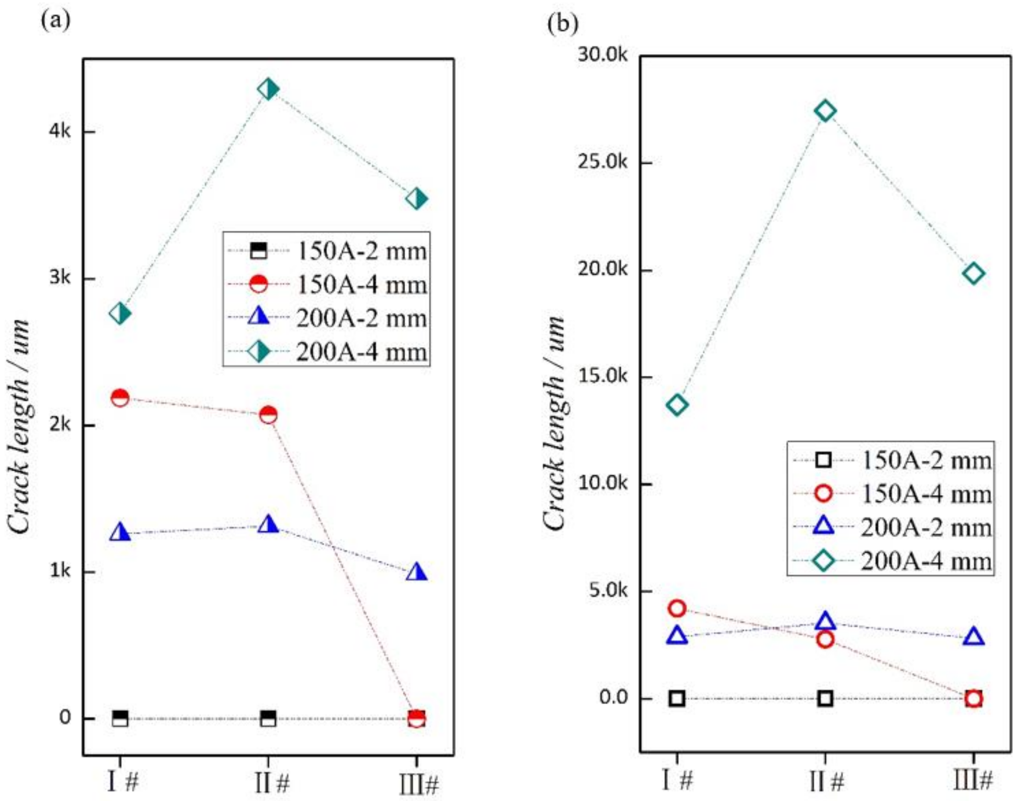
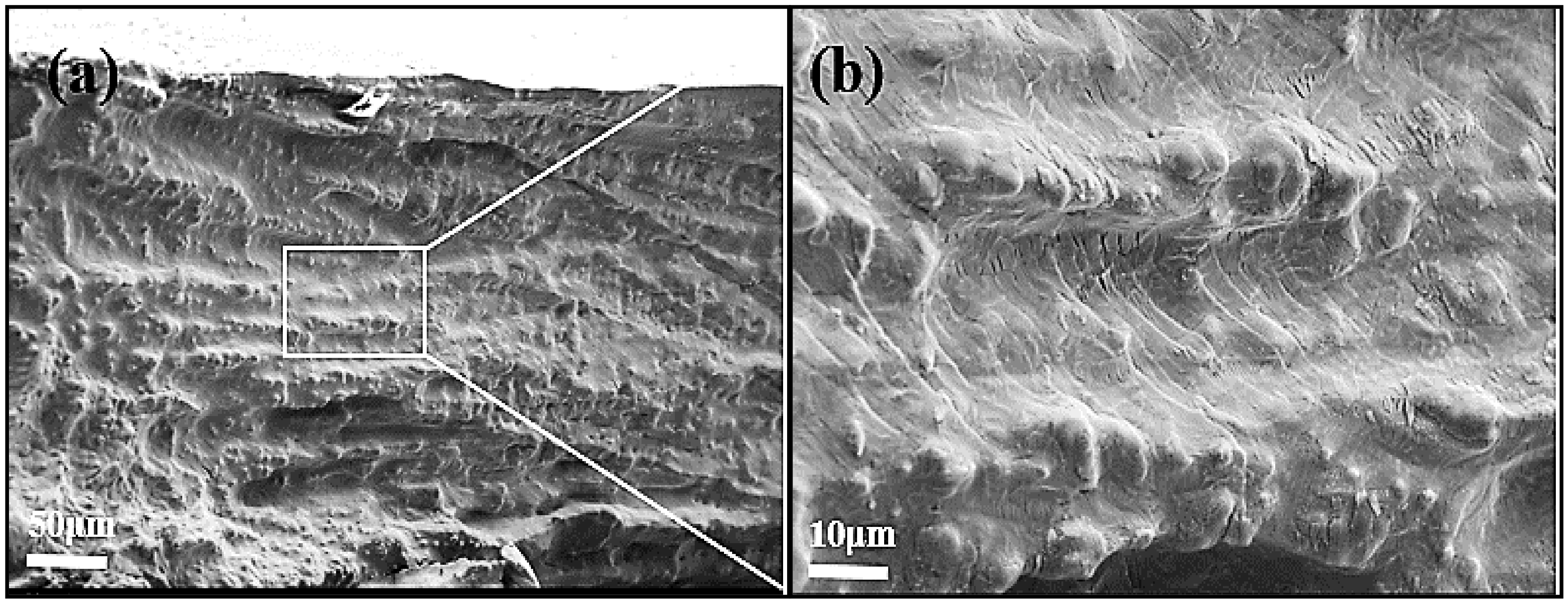
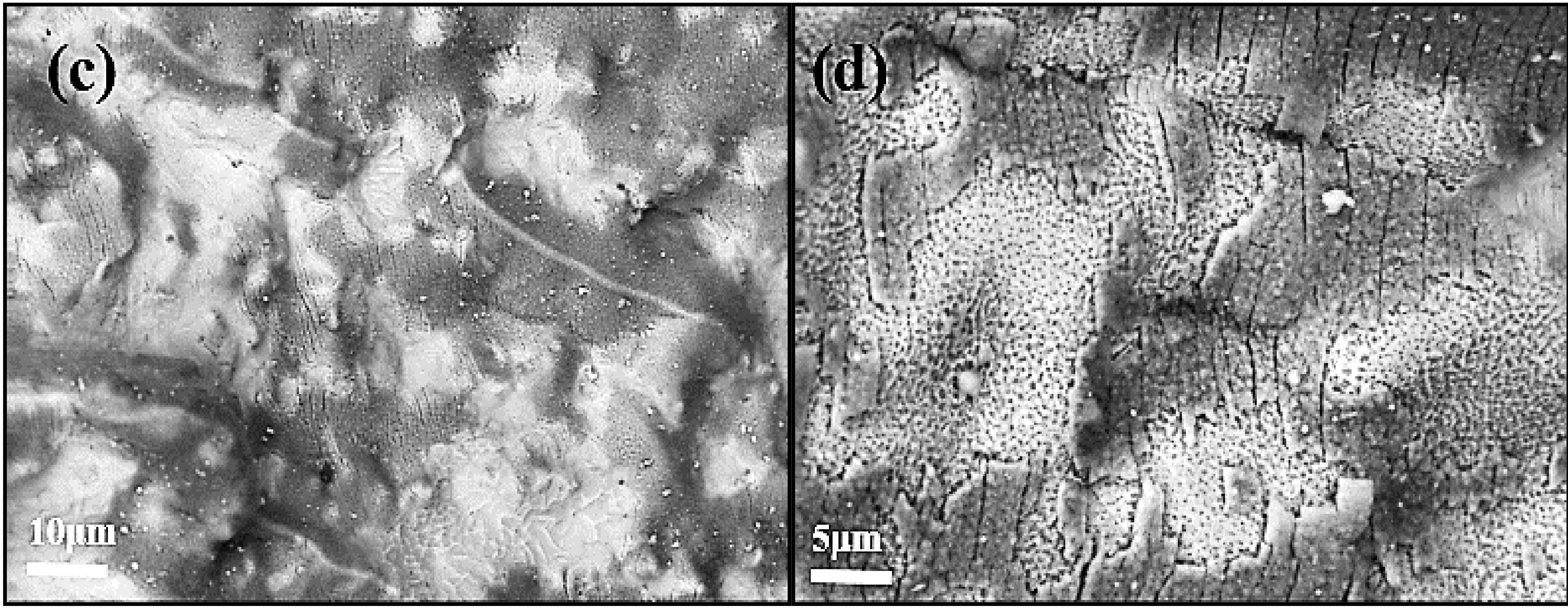
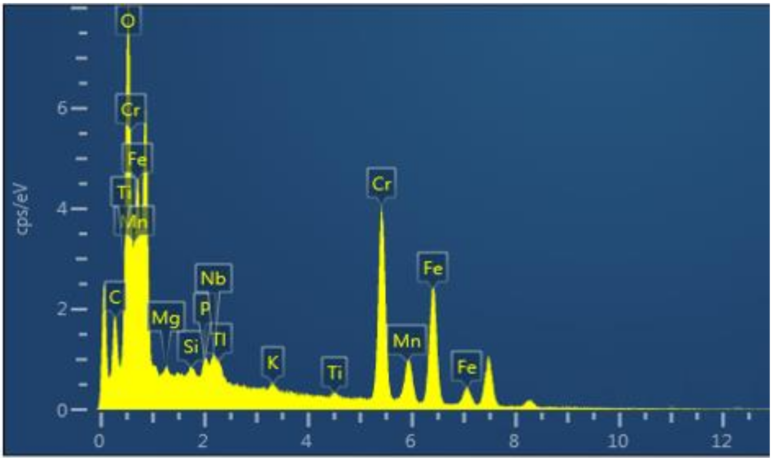
3.2. SFC Statistics, Fracture Morphology
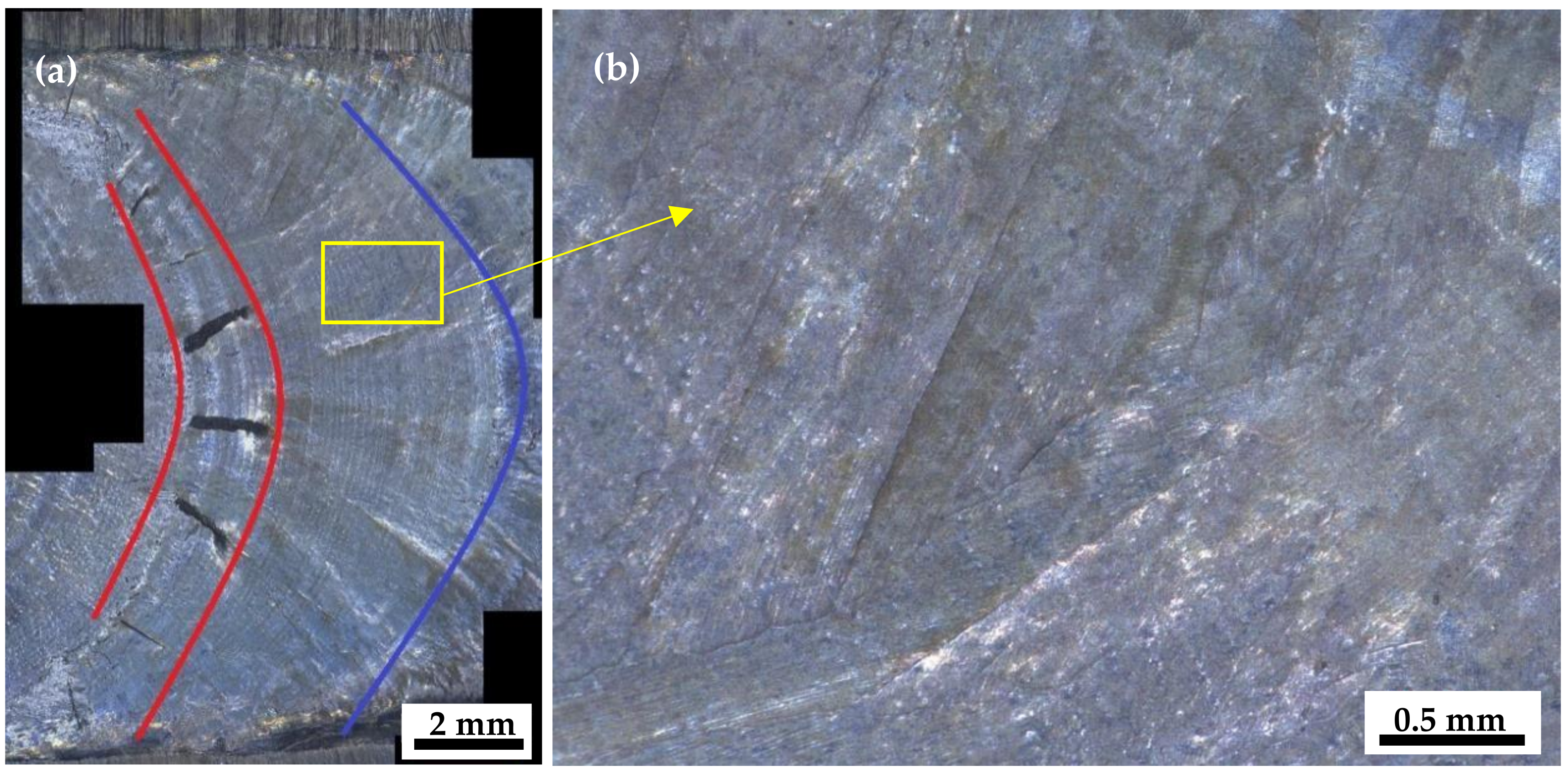
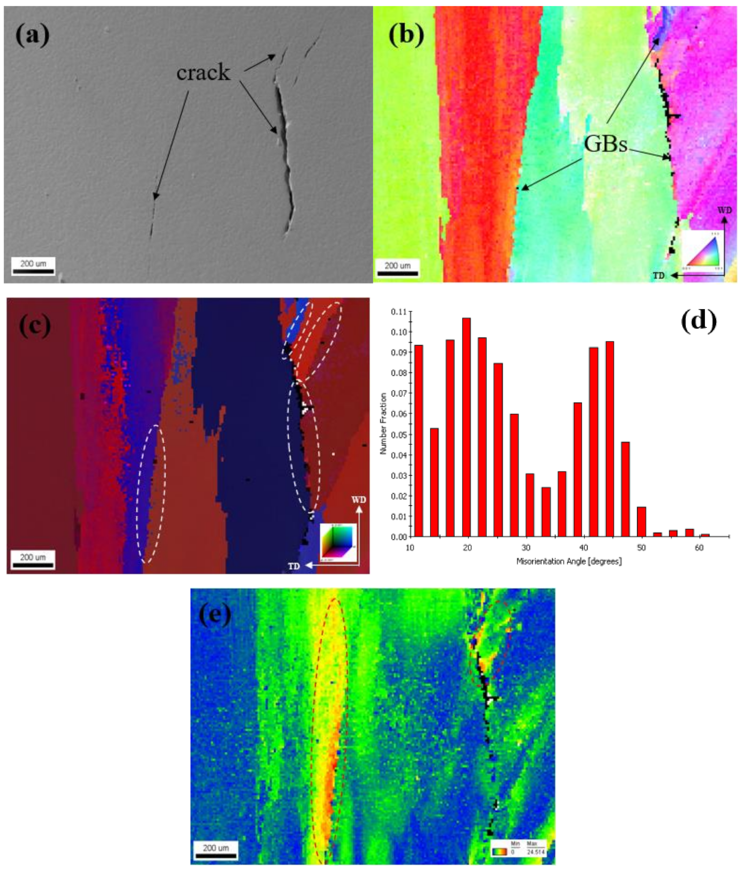
3.3. DDC Statistics, Morphology, and Adjacent Grain Orientation
4. Discussion
5. Conclusions
Author Contributions
Funding
Institutional Review Board Statement
Informed Consent Statements
Data Availability Statement
Conflicts of Interest
References
- Li, J.; Lu, Y.; Xin, L.; Shoji, T. The subsurface damage mechanism of Inconel 690 during fretting wear in pure water. Tribol. Int. 2018, 117, 152–161. [Google Scholar] [CrossRef]
- Guo, B.; Li, Y.; Zheng, J.; Li, F.; Li, X.; Du, X.; Yuan, L. Tribological properties of a halogen-free ionic liquid for Inconel 690–tungsten carbide contact. Tribol. Int. 2021, 163, 107153. [Google Scholar] [CrossRef]
- Mendez, P.F.; Barnes, N.; Bell, K.; Borle, S.D.; Gajapathi, S.S.; Guest, S.D.; Izadi, H.; Gol, A.K.; Gentry, W. Welding processes for wear resistant overlays. J. Manuf. Process. 2014, 16, 4–25. [Google Scholar] [CrossRef]
- Taheri, N.; Naffakh, H.; Ghaini, F.M. A new procedure for refurbishmentof power plant Superalloy 617 by pulsed Nd:YAG laser process. Opt. Laser Technol. 2017, 91, 71–79. [Google Scholar] [CrossRef]
- Soria, S.R.; Claramonte, S.; Yawny, A. Evolution of fretting wear with the number of cycles on Inconel 690 steam generator tubes against AISI 420 steel under gross slip conditions. Tribol. Int. 2021, 155, 106803. [Google Scholar] [CrossRef]
- Yushchenko, K.; Savchenko, V.; Chervyakov, N.; Zvyagintseva, M.A.; Guyot, E. Comparative hot cracking evaluation of welded joints of alloy 690 using filler metals INCONEL 52 and 52MSS, Weld. World 2011, 55, 28–35. [Google Scholar]
- Park, C.Y.; Rhee, H.; Ryu, K.W. Wear depth prediction for steam generator tubes using an estimated in situ wear coefficient. Nucl. Technol. 2018, 201, 23–40. [Google Scholar] [CrossRef]
- Wang, Z.; Xu, J.; Li, J.; Xin, L.; Lu, Y.; Shoji, T.; Takeda, Y.; Otsuka, Y.; Mutoh, Y. The synergy of corrosion and fretting wear process on Inconel 690 in the high temperature high pressure water environment. J. Nucl. Mater. 2018, 502, 255–262. [Google Scholar] [CrossRef]
- Ke, Y.; Xiong, J. Microstructure and mechanical properties of double-wire feed GTA additive manufactured 308L stainless steel. J. Mater. Process Tech. 2018, 26, 1503–1513. [Google Scholar]
- Dai, F.; Zhang, H.; Li, R. Process planning based on cylindrical or conical surfaces for five-axis wire and arc additive manufacturing. Rapid Prototyp. J. 2020, 26, 1405–1420. [Google Scholar] [CrossRef]
- Tang, S.; Wang, G.; Song, H.; Li, R.; Zhang, H. A novel method of bead modeling and control for wire and arc additive manufacturing. Rapid Prototyp. J. 2021, 27, 311–320. [Google Scholar] [CrossRef]
- King, C.; Frederick, G. Technical Basis for Preemptive Weld Overlays for Alloy 82/182 Butt Welds in PWRs(MPR-169) Revision 1; EPRI: Palo Alto, CA, USA, 2008. [Google Scholar]
- Xie, Y.; Wu, Y.; Burns, J.; Zhang, J. Characterization of stress corrosion cracks in Ni-based weld alloys 52, 52M and 152 grown in high-temperature water. Mater. Charact. 2016, 112, 87–97. [Google Scholar] [CrossRef] [Green Version]
- Li, G.; Zhang, M.; Huang, J.; Sun, Z.; Wu, Y. A comparative study on microstructure and properties of Inconel 52M overlays deposited by layer beam and GTA cladding. Int. J. Adv. Manuf. Technol. 2015, 81, 103–112. [Google Scholar] [CrossRef]
- Henderson, M.B.; Arrell, D.; Larsson, R.; Heobel, M.; Marchant, G. Nickel based superalloy welding practices for industrial gas turbine application. Sci. Technol. Weld. Join. 2004, 9, 13–21. [Google Scholar] [CrossRef]
- Pereira, F.G.L.; Lourenço, J.M.; Nascimento, R.M.D.; Castro, N.A. Fracture behavior and fatigue performance of Inconel 625. Mater. Res 2018, 21, e20171089. [Google Scholar] [CrossRef]
- Ahn, H.I.; Jeong, S.H.; Cho, H.H.; Lee, H.W. Ductility-dip cracking susceptibility of Inconel 690 using Nb content. J. Alloy. Compd. 2019, 783, 263–271. [Google Scholar] [CrossRef]
- Fang, X.; Ren, C.; Zhang, L.; Wang, C.; Huang, K.; Lu, B. A model of bead size based on the dynamic response of CMT-based wire and arc additive manufacturing process parameters. Rapid Prototyp. J. 2021, 27, 741–753. [Google Scholar] [CrossRef]
- Kulkarni, J.D.; Goka, S.B.; Parchuri, P.K.; Yamamoto, H.; Ito, K. Microstructure evolution along build direction for thin-wall components fabricated with wire-direct energy deposition. Rapid Prototyp. J In Press. 2021. [Google Scholar] [CrossRef]
- Zheng, L.; Schmitz, G.; Meng, Y.; Chellali, R.; Schlesiger, R. Mechanism of intermediate temperature embrittlement of Ni and Ni-based superralloys. Crit. Rev. Solid State Mater. Sci. 2012, 37, 181–214. [Google Scholar] [CrossRef]
- Rapetti, A.; Christien, F.; Tancret, F.; Todeschini, P. Effect of composition on ductility dip cracking of 690 nickel alloy during multipass welding. Mater. Today Commun. 2020, 24, 101163. [Google Scholar] [CrossRef]
- Kim, Y.; Nam, H.; Lee, J.; Park, C.; Moon, B.; Nam, D.-G.; Lee, S.H.; Kang, N. Hot-cracking resistivity of dissimilar clads using Inconel 52 and 308L stainless steel on carbon steel. J. Nucl. Mater. 2020, 533, 152103. [Google Scholar] [CrossRef]
- Barekat, M. Evaluation of solidification and microstructure in laser cladding Inconel 718 superalloy. Opt. Laser Technol. 2019, 120, 105761. [Google Scholar]
- Alizadeh-Sh, A.; Marashi, P.; Ranjbarnodeh, E.; Razavi, R.S. Prediction of solidification cracking by an empirical-statistical analysis for laser cladding of Inconel 718 powder on a non-weldable substrate. Opt. Laser Technol. 2020, 128, 106244. [Google Scholar] [CrossRef]
- Coniglio, N.; Cross, C.E. Towards Establishment of Weldability Testing Standards for Solidification Cracking; Springer International Publishing: Cham, Switzerland, 2016. [Google Scholar]
- Lippold, J.C.; Sowards, J.W.; Murray, G.M.; Alexandrov, B.T.; Ramirez, A.J. Weld solidification cracking in solid-solution strengthened Ni-base Filler Metal. Hot Cracking Phenomena. In Welds II; Springer: Berlin/Heidelberg, Germany, 2008; pp. 171–191. [Google Scholar]
- Lin, C.M. Relationships between microstructures and properties of buffer layer with Inconel 52M clad on AISI 316L stainless steel by GTAW processing. Surf. Coatings. Technol. 2013, 228, 234–241. [Google Scholar] [CrossRef]
- Hänninen, H.; Brederholm, A.; Saukkonen, T. Hot cracking susceptibility of Ni-base alloy dissimilar metal welds. Hot Cracking Phenomena. In Welds II; Springer: Berlin/Heidelberg, Germany, 2008; pp. 171–191. [Google Scholar]
- Shih, Y.J. Mitigation of hot cracking of alloy 52M overlay on cast stainless steel CF8A. Sci. Technol. Weld. Join 2013, 18, 566–572. [Google Scholar] [CrossRef]
- Chen, M.-Y.; Wu, T.-J.; Chen, T.-C.; Jeng, S.-L.; Tsay, L.-W. The comparison of cracking susceptibility of IN52M and IN52MSS overlay welds. Metals 2019, 9, 651–665. [Google Scholar] [CrossRef] [Green Version]
- Chu, H.A.; Young, M.C.; Chu, H.C.; Tsay, L.W.; Chen, C. The effect of Nb and S segregation on the solidification cracking of alloy 52M weld overlay on CF8 stainless steel. J. Mater. Eng. Perform. 2014, 23, 967–974. [Google Scholar] [CrossRef]
- Ko, G.; Seo, K.M.; Kim, H.J.; Hong, H. Characteristics of hot cracking in dissimilar joint of A690 overlay and stainless steel clad. Weld. World 2017, 61, 945–953. [Google Scholar] [CrossRef]
- Wei, X.; Xu, M.; Chen, J.; Yu, C.; Chen, J.; Lu, H.; Xu, J. Fractal analysis of Mo and Nb effects on Grain boundary character and hot cracking behavior for Ni-Cr-Fe alloys. Mater. Charact. 2018, 145, 65–76. [Google Scholar] [CrossRef]
- Wheeling, R.A.; Lippold, J.C. Characterization of weld metal microstructure in a Ni-30Cr alloy with additions of niobium and molybdenum. Mater. Charact. 2016, 115, 97–103. [Google Scholar] [CrossRef] [Green Version]
- Lippold, J.C.; Nissley, N.E. Further investigations of ductility-dip cracking in high chromium, Ni-base Filler Metals. Weld. World 2007, 51, 24–30. [Google Scholar] [CrossRef]


| Element | C | Si | Mn | P | S | Ni | Cr | N |
|---|---|---|---|---|---|---|---|---|
| Content | 0.029 | 0.14 | 0.75 | 0.001 | 0.001 | 9.52 | 18.86 | <0.01 |
| Element | C | Si | Mn | P | S | Ni | Cr | Mo | Al |
|---|---|---|---|---|---|---|---|---|---|
| Content | 0.015 | 0.14 | 0.75 | 0.001 | 0.001 | 59.25 | 30.20 | <0.01 | 0.10 |
| Element | Co | Cu | Ti | Fe | Nb + Ta | ||||
| Content | 0.001 | 0.04 | 0.22 | 8.04 | 0.84 |
| Current (A) | Walking Speed (mm/min) | Wire Feeding Speed (cm/min) | Base Voltage (V) | Peak Base Value Residence Time (S) |
|---|---|---|---|---|
| 160/120 | 66/110 | 1100/660 | 9.0 | 0.2/0.3 |
| Test Plate | Dilution Ratio (%) | Sample No. | |||
|---|---|---|---|---|---|
| I#(1 mm Cladding metal) | ~39 | I#-1 | I#-2 | I#-3 | I#-4 |
| II#(2 mm Cladding metal) | ~15 | II#-1 | II#-2 | II#-3 | II#-4 |
| III#(3 mm Cladding metal) | ~6 | III#-1 | III#-2 | III#-3 | III#-4 |
| Test Board Type | Test Parameters (Current-Down Stroke) | |||
|---|---|---|---|---|
| 150 A-2 mm | 150 A-4 mm | 200 A-2 mm | 200 A-4 mm | |
| I# |  | 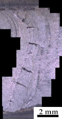 | 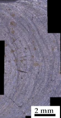 |  |
| II# | 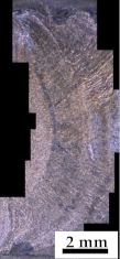 | 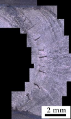 | 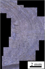 | 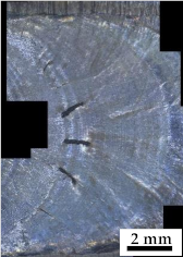 |
| III# |  | 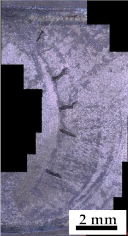 | 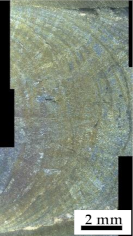 |  |
| Elements | C | Cr | Fe | Ni | Mn | O | Ti | P | K | Nb | Mg | Si |
|---|---|---|---|---|---|---|---|---|---|---|---|---|
| Fraction (wt.%) | 16.6 | 22.04 | 21.91 | 15.07 | 2.71 | 17.13 | 0.37 | 0.68 | 0.31 | 1.74 | 0.42 | 1.01 |
| Alloying Element Content (wt.%) | |||||||||
|---|---|---|---|---|---|---|---|---|---|
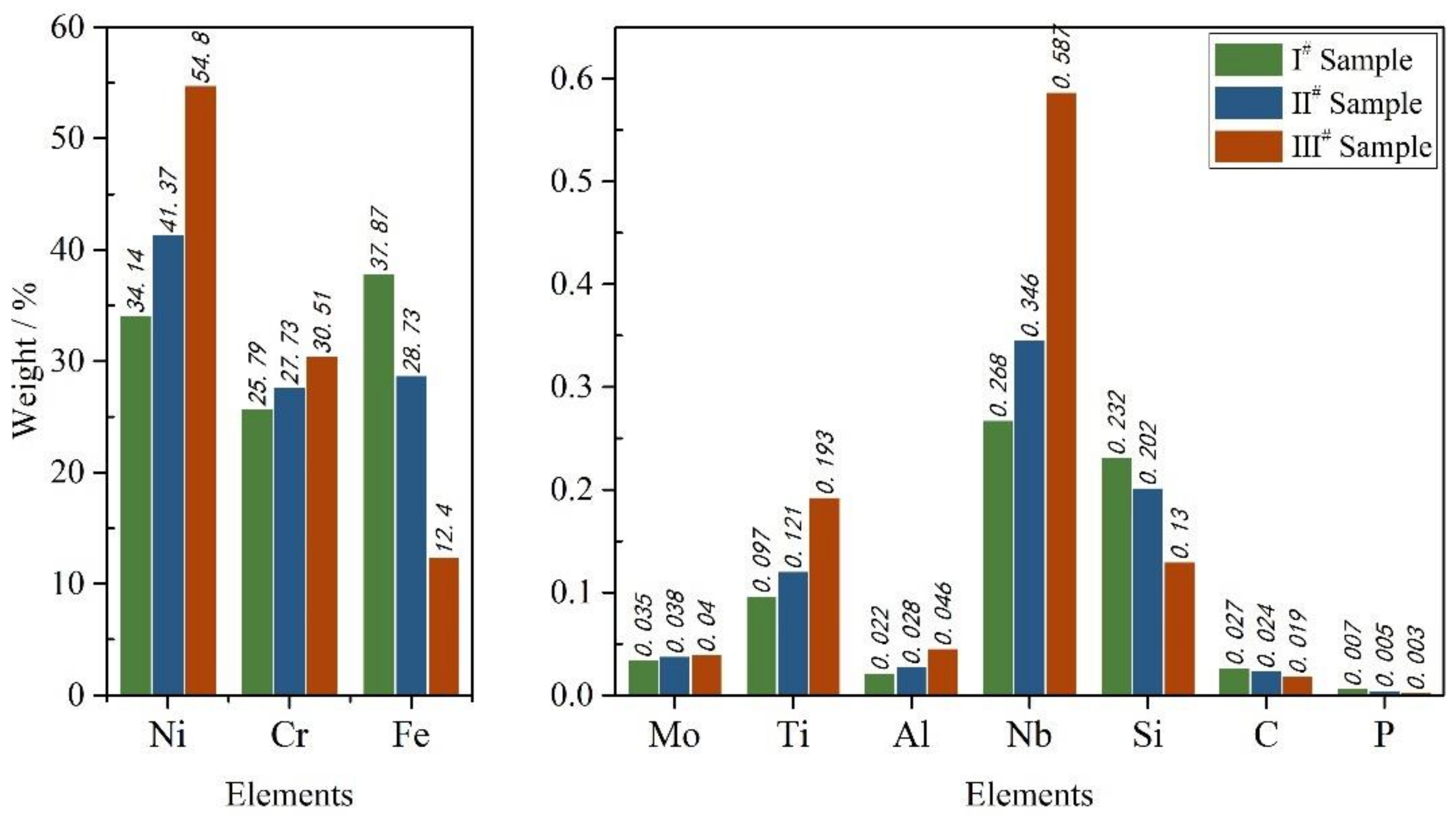
| Element | C | Si | Mn | P | S | Ni | Cr | Mo | Al |
| I#Test board | 0.027 | 0.232 | 0.907 | 0.007 | 0.004 | 34.140 | 25.790 | 0.035 | 0.022 |
| II#Test board | 0.024 | 0.202 | 0.894 | 0.006 | 0.004 | 41.370 | 27.730 | 0.038 | 0.028 |
| III#Test board | 0.019 | 0.130 | 0.872 | 0.003 | 0.004 | 54.800 | 30.510 | 0.040 | 0.046 |
| Element | Co | Cu | Ti | Fe | Nb | Ta | |||
| I#Test board | 0.112 | 0.028 | 0.097 | 37.87 | 0.268 | 0.007 | |||
| II#Test board | 0.087 | 0.028 | 0.121 | 28.730 | 0.346 | 0.005 | |||
| III#Test board | 0.040 | 0.026 | 0.193 | 12.400 | 0.587 | 0.003 | |||
Publisher’s Note: MDPI stays neutral with regard to jurisdictional claims in published maps and institutional affiliations. |
© 2021 by the authors. Licensee MDPI, Basel, Switzerland. This article is an open access article distributed under the terms and conditions of the Creative Commons Attribution (CC BY) license (https://creativecommons.org/licenses/by/4.0/).
Share and Cite
Lu, L.; Cai, Z.; Yang, J.; Liang, Z.; Sun, Q.; Pan, J. Study on the Hot Cracking Law of Inconel 690/52M Welding Material on F304LN Base Metal by Multi-Layer Cladding. Metals 2021, 11, 1540. https://doi.org/10.3390/met11101540
Lu L, Cai Z, Yang J, Liang Z, Sun Q, Pan J. Study on the Hot Cracking Law of Inconel 690/52M Welding Material on F304LN Base Metal by Multi-Layer Cladding. Metals. 2021; 11(10):1540. https://doi.org/10.3390/met11101540
Chicago/Turabian StyleLu, Li, Zhipeng Cai, Jia Yang, Zhenxin Liang, Qian Sun, and Jiluan Pan. 2021. "Study on the Hot Cracking Law of Inconel 690/52M Welding Material on F304LN Base Metal by Multi-Layer Cladding" Metals 11, no. 10: 1540. https://doi.org/10.3390/met11101540
APA StyleLu, L., Cai, Z., Yang, J., Liang, Z., Sun, Q., & Pan, J. (2021). Study on the Hot Cracking Law of Inconel 690/52M Welding Material on F304LN Base Metal by Multi-Layer Cladding. Metals, 11(10), 1540. https://doi.org/10.3390/met11101540