On the Friction Stir Welding of Al 7075 Thin Sheets


Abstract
1. Introduction
2. Materials and Methods
3. Results and Discussion
4. Conclusions
Author Contributions
Funding
Institutional Review Board Statement
Informed Consent Statement
Data Availability Statement
Conflicts of Interest
References
- Liu, Z.; Ji, S.; Meng, X. Joining of magnesium and aluminum alloys via ultrasonic assisted friction stir welding at low temperature. Int. J. Adv. Manuf. Technol. 2018, 97, 4127–4136. [Google Scholar] [CrossRef]
- Mubiayi, M.P.; Akinlabi, E.T. Friction Stir Welding of Dissimilar Materials between Aluminum Alloys and Copper—An Overview. In Proceedings of the World Congress on Engineering, London, UK, 3–5 July 2013; Volume 3. [Google Scholar]
- Galvao, I.; Verdera, D.; Gesto, D.; Loureiro, A.; Rodrigues, D.M. Influence of aluminum alloy type on dissimilar friction stir lap welding of aluminum to copper. J. Mater. Process. Technol. 2013, 213, 1920–1928. [Google Scholar] [CrossRef]
- Wang, G.L.; Li, J.L.; Wang, W.L.; Xiong, J.T.; Zhang, F.S. Rotary friction welding on dissimilar metals of aluminum and brass by using pre-heating method. Int. J. Adv. Manuf. Technol. 2018, 99, 1293–1300. [Google Scholar] [CrossRef]
- Cicalăa, E.; Duffetb, G.; Andrzejewskib, H.; Greveyb, D.; Ignatab, S. Hot cracking in Al–Mg–Si alloy laser welding—Operating parameters and their effects. Mater. Sci. Eng. 2005, 395, 1–9. [Google Scholar] [CrossRef]
- Thomas, W.M.; Nicholas, E.D.; Needham, J.C.; Murch, M.G.; Temple-Smith, P.; Dawes, C.J. Improvements related to Friction Welding. International Patent Application No. PCT/GB92/02203, 8 December 1991. [Google Scholar]
- Saeid, T.; Abdollah-zadeh, A.; Sazgari, B. Weldability and mechanical properties of dissimilar aluminum copper lap joints made by friction stir welding. J. Alloy. Compd. 2010, 490, 652–655. [Google Scholar] [CrossRef]
- Cam, G. Friction stir welded structural materials: Beyond Al-alloys. Int. Mater. Rev. 2011, 56, 1–48. [Google Scholar] [CrossRef]
- Kallee, S.W.; Davenport, J.; Nicholas, E.D. Railway Manufacturers Implement Friction Stir Welding. Weld. J. 2002, 81, 47–50. [Google Scholar]
- Vishwanath, S.G.; Shivakumar, B. Comparison of friction stirs welding technique with conventional welding methods. IJRET 2014, 3, 2321–7308. [Google Scholar]
- Kumar, R.; Ghost, A.; Chattopadhyaya, S. Emerging friction stir welding for aluminium and its applications. J. Manuf. Ind. Eng. 2014, 14, 1–5. [Google Scholar] [CrossRef][Green Version]
- Mishra, R.S.; Ma, Z.Y. Friction stir welding and processing. Mater. Sci. Eng. R Rep. 2005, 50, 1–78. [Google Scholar] [CrossRef]
- Mahoney, M.W.; Rhodes, C.G.; Flintoff, J.G.; Bingel, W.H.; Spurling, R.A. Properties of Friction-stir-welded 7075 T651 Aluminum. Metall. Mater. Trans. A 1998, 29, 1955–1964. [Google Scholar] [CrossRef]
- Galvão, I.; Leitão, C.; Loureiro, A.; Rodrigues, D. Friction Stir Welding of Very Thin Plates. Soldag. Insp. 2012, 17, 2–10. [Google Scholar] [CrossRef]
- TWI. Microstructure Classification of Friction Stir Welds. Available online: http://www.twi.co.uk/content/fswqual.html (accessed on 25 September 2010).
- Zhang, D.; Wang, X.; Pan, Y.; Hou, S.; Zhang, J.; Zhuang, L.; Zhou, L. Friction stir welding of novel T-phase strengthened Zn-modified Al–Mg alloy. J. Mater. Sci. 2021, 56, 5283–5295. [Google Scholar] [CrossRef]
- Li, M.; Zhang, C.; Wang, D.; Zhou, L.; Wellmann, D.; Tian, Y. Friction Stir Spot Welding of Aluminum and Copper: A Review. Materials 2020, 13, 156. [Google Scholar] [CrossRef] [PubMed]
- Li, B.; Wang, X.M.; Chen, H. Influence of heat treatment on the strength and fracture toughness of 7N01 aluminum alloy. J. Alloy. Compd. 2016, 678, 160–166. [Google Scholar] [CrossRef]
- Oliveira, A.F.; De Barros, M.C.; Cardoso, K.R.; Travessa, D.N. The Effect of RRA on the Strength and SCC Resistance on AA7050 and AA7150 Aluminium Alloys. Mater. Sci. Eng. A 2004, 379, 321–326. [Google Scholar] [CrossRef]
- Zhang, S.F.; Wang, X.M.; Chen, H. Stress corrosion cracking of cabinet of 7003 aluminum alloy. J. Mater. Eng. 2015, 43, 105–112. [Google Scholar] [CrossRef]
- Wang, X.M.; Liao, X.Y.; Ma, C.P. Effects of chemical composition on the corrosion behavior of A7N01S-T5 Al alloys. Int. J. Mod. Phys. B 2015, 29, 27–36. [Google Scholar] [CrossRef]
- ASM Handbook. Properties and Selection: Nonferrous Alloys and Special-Purpose Materials, 10th ed.; ASM International: Metals Park, OH, USA, 1990; Volume 2. [Google Scholar]
- Campbell, F.C. Manufacturing Technology for Aerospace Structural Materials; Elsevier: Amsterdam, The Netherlands, 2006. [Google Scholar]
- Burek, R.; Wydrzyński, D.; Kubit, A.; Łogin, W. The influence of the shoulder depth on the properties of the thin sheet joint made by FSW technology. Aircr. Eng. Aerosp. Technol. 2020. [Google Scholar] [CrossRef]
- Mehri, A.; Abdollah-Zadeh, A.; Habibi, N.; Hajian, M.; Wang, J.T. The Effects of Rotational Speed on Microstructure and Mechanical Properties of Friction Stir-Welded 7075-T6 Thin Sheet. J. Mater. Eng. Perform. 2020, 29, 2316–2323. [Google Scholar] [CrossRef]


| WNr 1,6582/DIN 34CrNiMo6—∅16 mm | |||||||
|---|---|---|---|---|---|---|---|
| C | Mn | Si | P | S | Cr | Mo | Ni |
| 0.30–0.38 | 0.5–0.8 | 0.40 max | 0.025 max | 0.035 max | 1.3–1.7 | 0.15–0.30 | 1.3–1.7 |
| Al Alloy | Si | Fe | Cu | Mn | Mg | Cr | Ni | Zn | Ti | Ga | V | Al |
|---|---|---|---|---|---|---|---|---|---|---|---|---|
| 7075 | 0.12 | 0.2 | 1.4 | 0.063 | 2.53 | 0.2 | 0.004 | 5.62 | 0.03 | 0.008 | 0.016 | bal. |
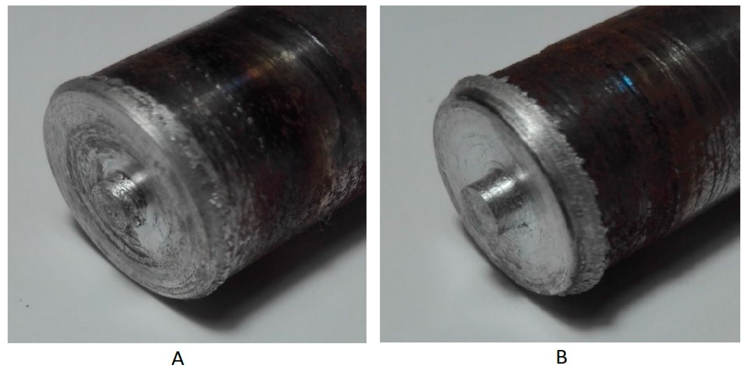
| Tool Geometry (Dimensions in mm) | Tool A | Tool Β |
|---|---|---|
| Flat Shoulder 16 Cylindrical Pin 3 Height of Pin 1.8 | Flat Shoulder 16 Cylindrical Pin 4 Height of Pin 1.8 | |
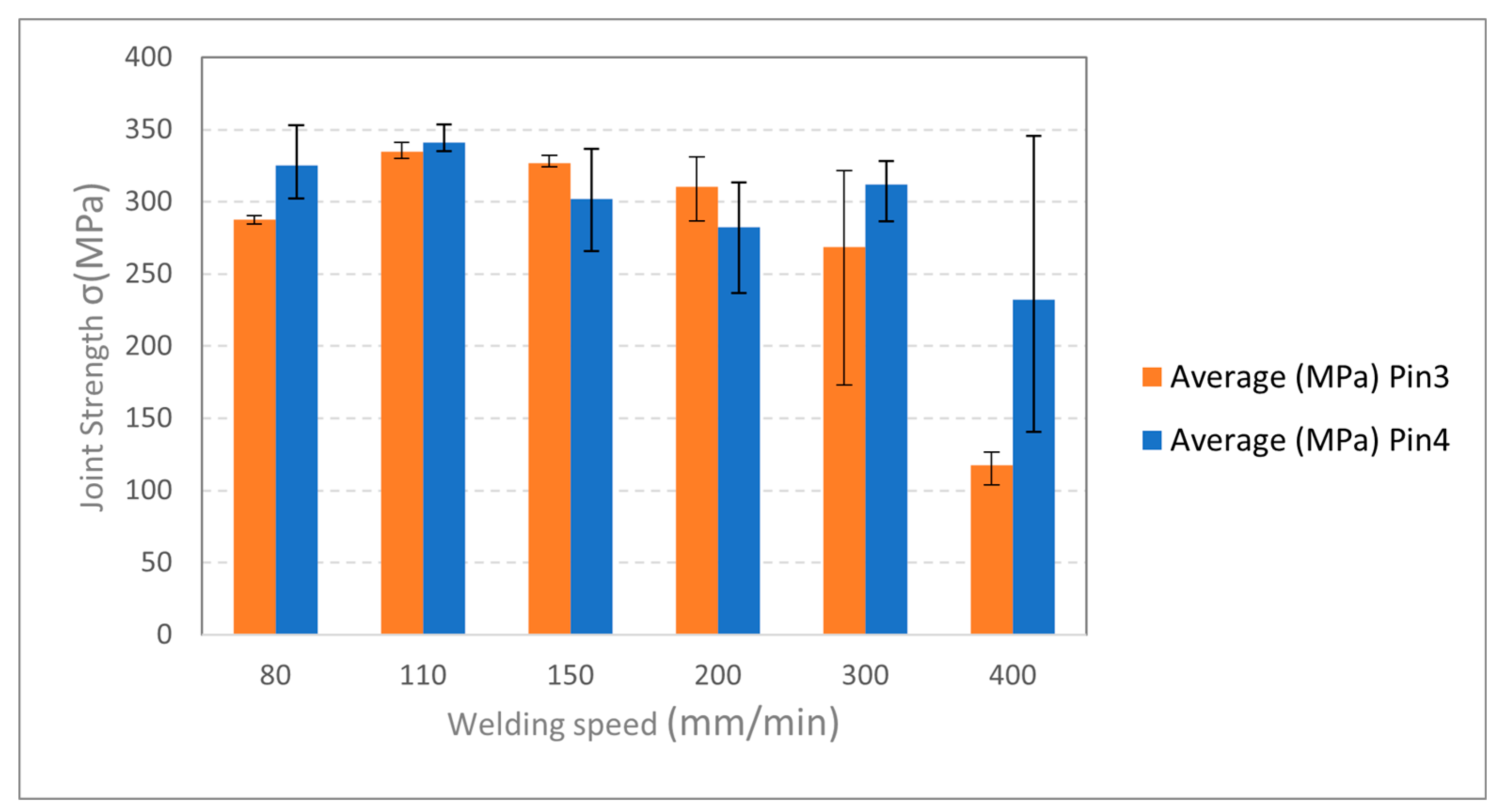
| Rotation speed (rpm) | 1000–2500 | |
| Welding speed (mm/min) | 80–800 | |
| Tool tilting angle (°) | 0° | |
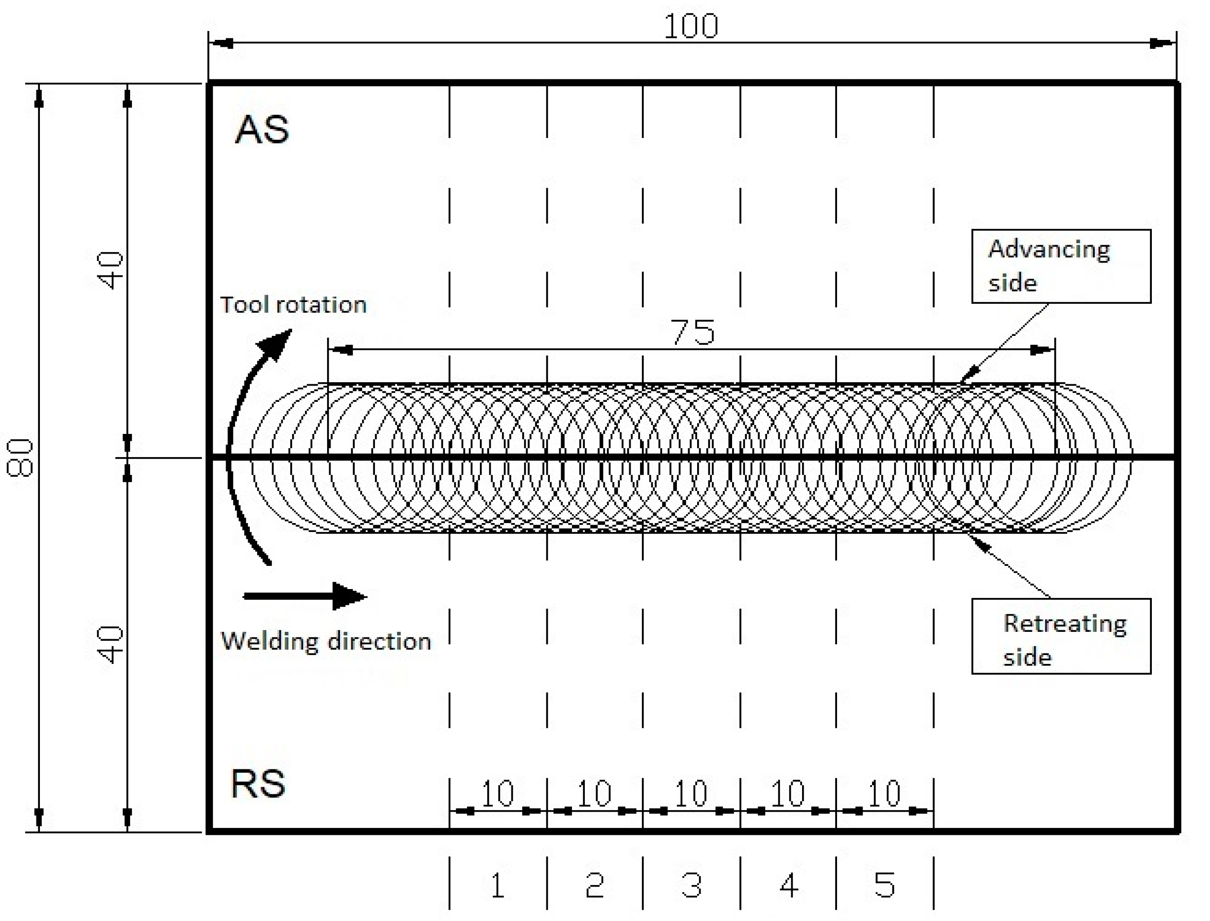
| Specimen dimensions (mm) | 40 × 100 × 2 | |
Publisher’s Note: MDPI stays neutral with regard to jurisdictional claims in published maps and institutional affiliations. |
© 2020 by the authors. Licensee MDPI, Basel, Switzerland. This article is an open access article distributed under the terms and conditions of the Creative Commons Attribution (CC BY) license (http://creativecommons.org/licenses/by/4.0/).
Share and Cite
Dimopoulos, A.; Vairis, A.; Vidakis, N.; Petousis, M. On the Friction Stir Welding of Al 7075 Thin Sheets. Metals 2021, 11, 57. https://doi.org/10.3390/met11010057
Dimopoulos A, Vairis A, Vidakis N, Petousis M. On the Friction Stir Welding of Al 7075 Thin Sheets. Metals. 2021; 11(1):57. https://doi.org/10.3390/met11010057
Chicago/Turabian StyleDimopoulos, Andreas, Achilles Vairis, Nectarios Vidakis, and Markos Petousis. 2021. "On the Friction Stir Welding of Al 7075 Thin Sheets" Metals 11, no. 1: 57. https://doi.org/10.3390/met11010057
APA StyleDimopoulos, A., Vairis, A., Vidakis, N., & Petousis, M. (2021). On the Friction Stir Welding of Al 7075 Thin Sheets. Metals, 11(1), 57. https://doi.org/10.3390/met11010057