Article

Alumina Reinforcement of Inconel 625 Coatings by Cold Gas Spraying

Thermal Spray Center CPT, University of Barcelona, Martí i Franqués 1, 7a Planta, 08028 Barcelona, Spain
*
Author to whom correspondence should be addressed.
Metals 2020, 10(9), 1263; https://doi.org/10.3390/met10091263
Submission received: 27 May 2020 / Revised: 10 September 2020 / Accepted: 15 September 2020 / Published: 18 September 2020

Abstract

:
Reinforced Inconel625 coatings have been successfully deposited by means of cold gas spray (CGS). Alumina has been simultaneously sprayed achieving a homogeneous distribution along the deposit with good cohesion between particles. The aim of this study was to investigate whether ceramic reinforcement could improve the mechanical and tribological properties of Inconel625 cold-sprayed coatings, while keeping the oxidation and corrosion resistance capacity. Furthermore, alumina particles were found to improve the spraying feasibility, by avoiding WC nozzle clogging during the process. A proper optimization of the spraying conditions was carried out in order to obtain the lowest possible porosity and best embedment of the alumina. Then, the mechanical and tribological properties as well as corrosion and oxidation behavior were characterized. Alumina acts as a reinforcement, improving the effects of abrasive and sliding wear. Regarding the oxidation and corrosion behavior, the coatings exhibit reasonably good oxidation resistance at temperatures up to 900 °C. The electrochemical corrosion performance in NaCl solution showed potentially lower noble corrosion values and corrosion current densities than bulk Inconel.

1. Introduction

Inconel alloys are oxidation- and corrosion-resistant materials well suited for service in environments subject to extreme pressure and heat. Specifically, Inconel625 is a Ni–Cr–Mo alloy that was developed for high-temperature strength. Its highly alloyed composition provides a good level of general corrosion resistance in a wide range of oxidizing and non-oxidizing environments. Some of its typical applications are in chemical processing, aerospace and marine engineering, pollution-control equipment, and nuclear reactors [1,2,3].
Inconel625 and 718 coatings obtained by conventional thermal spray processes such as high-velocity oxy fuel (HVOF) have been extensively used in the power industry to improve the corrosion and wear resistance of metallic surfaces [4,5,6]. Most of the studies relate the corrosion activity to the presence of more or less oxidation and porosity content; for example, according to Planche et al., electrochemical activation time increases with the oxygen/fuel ratio used in the combustion, leading to a higher coating density due to a more difficult electrolyte penetration into the coating [6].
Low thermal, high kinetic energy-based processes such as cold gas spray (CGS) offer promising techniques for the avoidance of porosity and oxidation problems [7,8,9]. These techniques initially proved to be well suited to addressing the plastic deformation of ductile raw materials with relatively low melting points, high densities, low mechanical strength, and low heat capacities, such as Zn and Cu. The subsequent development of gun systems, however, has made the challenge of effectively treating higher strength materials such as Inconel more achievable [10].
Our previous studies [11,12] investigated the mechanical and microstructural properties as well as the fatigue behavior of Inconel625 cold-gas-sprayed coatings, using different starting particle dimensions (−45 + 15 μm, spherical shape) under different process conditions. Many authors [13,14,15] have used different particle shapes of feedstock powder to demonstrate that changing gas pressure and temperature greatly influences the particle velocity, producing denser and less porous coatings and spherical and smaller particles, giving better results. The results have shown that the best combination of low porosity and high flattening ratio for Inconel [13] was achieved using Kinetics 4000 equipment (Impact Innovations GmbH, Rattenkirchen, Germany) with a gas temperature of 800 °C at 4 MPa pressure. Moreover, the coatings produced with larger dimensions of starting particles showed lower porosity levels than the finer particles. Monotonic bend tests were performed on different V-notched (30°, 60°, and 90°) substrates coated under the above-mentioned process conditions; it was found, during cyclic tests, that the crack growth rate increases with decreasing V-notch aperture and increasing maximum bending load. Increasing the process conditions up to 1000 °C and 5 MPa, using PSC100 equipment (Plasma Giken Co. Ltd., Saitama, Japan) [12], showed lower levels of porosity, higher hardness values, and improved corrosion properties. The microstructurally and mechanically improved features led to improved fatigue properties under crack initiation and growth tests in bending.
Recent results from other authors also studying the microstructural features and mechanical and corrosion properties of cold-gas-sprayed Inconel625 coatings demonstrate the growing interest in this topic. The chronology starts in 2017, when Chaudhuri et al. [16] illustrated the microstructural evolution of Inconel625 coatings cold-sprayed onto a medium carbon steel substrate, and observed a significant strain accumulation in the coating due to severe deformation of the particles. Moreover, the substrate region close to the coating–substrate interface showed a heavy grain refinement, as a result of the severe deformation of the substrate by particle impact, followed by thermally activated dynamic recrystallization. In the same year, the high-temperature corrosion of Inconel625 cold-gas-sprayed coatings was evaluated by Fantozzi et al. [17], who subjected the coatings to chlorine-induced active oxidation. This was done because Inconel625 coatings are applied as protective coatings in many industrial fields where high-temperature corrosion resistance is required. The cold gas spray coatings were sprayed onto stainless steel substrates, using two different gas processes (N2 and He) and two different gas-atomized powders (fine and coarse). All the coatings performed well, preventing corrosion of the substrate and acting as a barrier against the corrosive environment, notwithstanding the conclusion that combining the finest particles with the use of He in the gas process seems to have better results.
In a very recent study, Azarmi et al. [18] investigated the elastic properties of Inconel625 powders that were cold gas sprayed onto aluminum substrate. They concluded that the major microstructural feature affecting the Young’s modulus of cold-gas-sprayed coating is the dislocation density at the grain boundaries. This result is a consequence of the stress/strain test that indicates a reduction of the in-plane Young’s modulus of the CGS-deposited coating of about 30%, as compared to the bulk material. To better understand this reduction, they performed transmission electron microscopy (TEM) experiments, which confirmed the occurrence of a very high dislocation density at the grains and grain boundaries in CGS-deposited coatings.
Given the parallel growth of CGS technology, not only as a coating process but also as an additive manufacturing technique, Sun et al. [19] used it to cold gas spray Inconel625 in a process to repair metal components. The resulting low porosity levels and high hardness values demonstrated the good quality of the cold-gas-sprayed Inconel625 coatings and showed that cold gas spray is a promising additive manufacturing technique for repair applications of Ni-based superalloy parts [20].
As previously mentioned, Inconel718 is also an important alloy used in the aerospace sector and its spraying feasibility is worth considering. Levasseur et al. [21] demonstrated that a cold gas spray process can be used advantageously to produce high density Inconel718 coatings, but post-deposition sintering was necessary because of a lack of inter-particle bonding. Singh et al. [22] investigated the influence of coating thickness on residual stress and the adhesion strength of Inconel718 coatings sprayed onto Inconel718 substrate. Luo et al. [23] used an in situ micro-forging technique to reduce the porosity of Inconel718 coatings deposited onto 316 L substrate. To introduce the micro-forging effect during spray deposition, 410 martensitic stainless steel powders with a spherical morphology were blended into the Inconel718 powders. The authors concluded that porosity present in the Inconel718 deposit was gradually reduced and the inter-particle bonding improved with the enhanced in situ micro-forging effect [24].
Complementing the above-mentioned works, Ni-based superalloy coatings reinforced with alumina have also been observed to improve wear resistance properties. For example, Ni20Cr was successfully deposited by spraying it in a blend with ceramic alumina particles, leading to many practical advantages [25]. Ceramic particles have been added by other authors to produce improved coatings [26,27,28,29,30,31,32,33] and were observed to function in more ways than just reinforcing, such as (i) preventing nozzle clogging, (ii) activating the sprayed surface, and (iii) helping in the compaction of the structure [25,26].
Following our previous studies, we wanted to go one step further by producing alumina-reinforced Inconel625 cold-gas-sprayed coatings with different Al2O3-to-Inconel625 ratios and evaluating the main mechanical, tribological, corrosion, and oxidation properties of the optimized deposits.

2. Materials and Methods

Inconel625 (Diamalloy 1005 from Sulzer Metco (Pfäffikon, Freienbach, Switzerland); wt.%: Cr = 21.5; Fe = 2.5; Mo = 9.0; Nb + Ta = 3.7; Ni bal.) and #220 mesh alumina (from Imerys Fused Minerals, Villach, Austria) powders were sprayed onto flat and cylindrical carbon steel substrates. Both powders were sprayed simultaneously using Kinetics 4000 Cold Gas equipment and a D24 WC nozzle, using two powder feeders instead of powder mixtures. Nitrogen was used as the process gas, sprayed at a pressure of 40 bars, at 800 °C and from a distance of 40 mm. Feeding conditions were then modified leading to several Inconel/alumina ratios, e.g., (i) 23, (ii) 30, (iii) 35, and (iv) 45 wt.% of Al2O3. Particle size distributions were measured by the laser scattering test (Beckman Coulter LS Particle Size Analyzer, Indianapolis, IN, USA; fluid ethanol).
The substrates were first activated by grit blasting with alumina #24 to remove surface oxidation and promote surface roughness. The characterization of the samples included particle size distribution, X-ray diffraction, and cross-sectional SEM images. Hardness measurements were performed by means of Vickers indentation at 300 g load; the average was taken from 20 indentations per sample. The adherence of the coatings was measured in accordance with ASTM C633. The glue used was HTK Ultra Bond 100 (Hamburg, Germany), with measured adherence of 73.7 ± 1.2 MPa. Servosis MCH-102 ME equipment (Madrid, Spain) was used for the tests. Abrasion rubber wheel tests (ASTM G65-00) [34] were carried out to quantify the abrasive wear resistance, applying a load of 50 N. Sliding ball-on-disk tests were performed under ASTM G99-03 [35] using a hard metal ball as counterpart with a 5 N load. The corrosion resistance of samples was evaluated by means of electrochemical measurements in 80 mL of an aerated and unstirred 3.4% NaCl solution on polished samples obtained from the as-prepared coating by abrasion with P600, P1200, and P4000 SiC papers and followed by polishing with 1 and 0.5 μm diamond suspensions. A conventional three-electrode cell was used, with saturated Ag/AgCl/KCl as reference electrode, a Pt-wire as counter electrode, and the as-sprayed samples as the working electrode. A PC-programmed EG&G 263A potentiostat/galvanostat (Princeton Applied Research, Princeton, NJ, US) was employed. For all the specimens, the following procedure was applied: once the open-circuit potential was stabilized, a linear polarization was performed in the small potential range around the open-circuit potential, EOC (Evolution of Open Circuit potential, ±5 mV/EOC), at a scan rate of 0.05 mV/s, and finally the potentiodynamic curves were recorded, starting at −100 mV/EOC and going up to +350 mV/EOC, at a rate of 0.166 mV/s.

3. Results

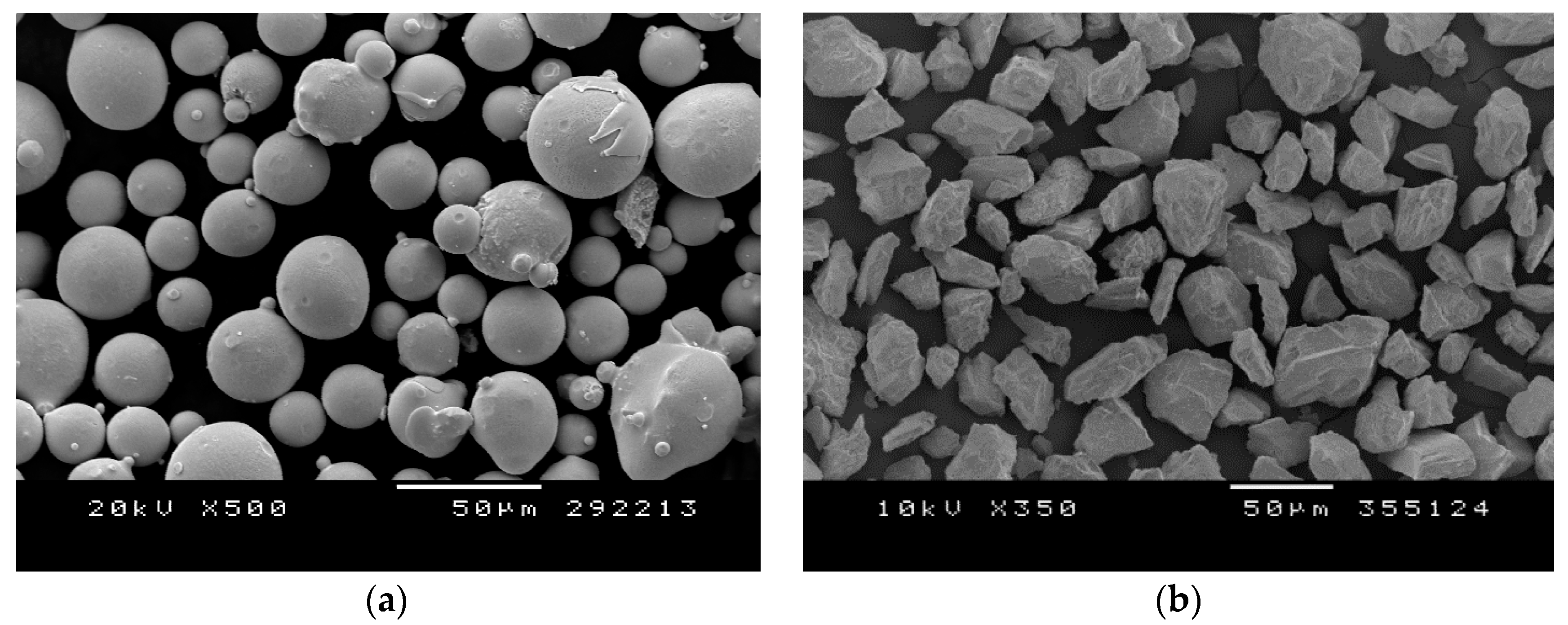
3.1. Powder Characterization

The SEM image of the gas atomized Inconel powder that has a spherical morphology and its particle size distribution of −45 + 17 μm are shown in Figure 1a and Table 1a, and the SEM image of the alumina reinforcing powder with its irregular blocky shape and its particle size distribution of −118 + 37 μm are shown in Figure 1b and Table 1b.
Table 1 show the particle size distribution of both powders. It can be seen that the particle size range of the reinforcing alumina is much larger; actually, the coarse alumina particles are assumed not to be properly bonded.

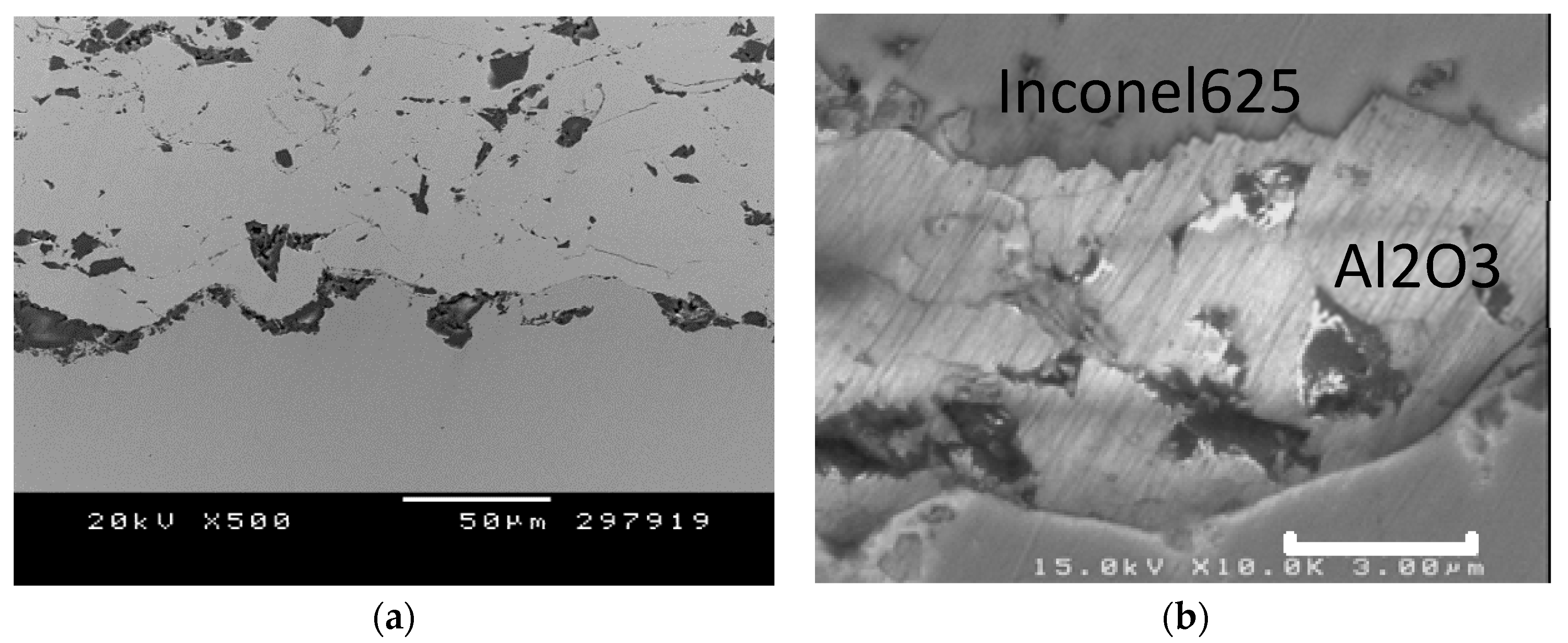
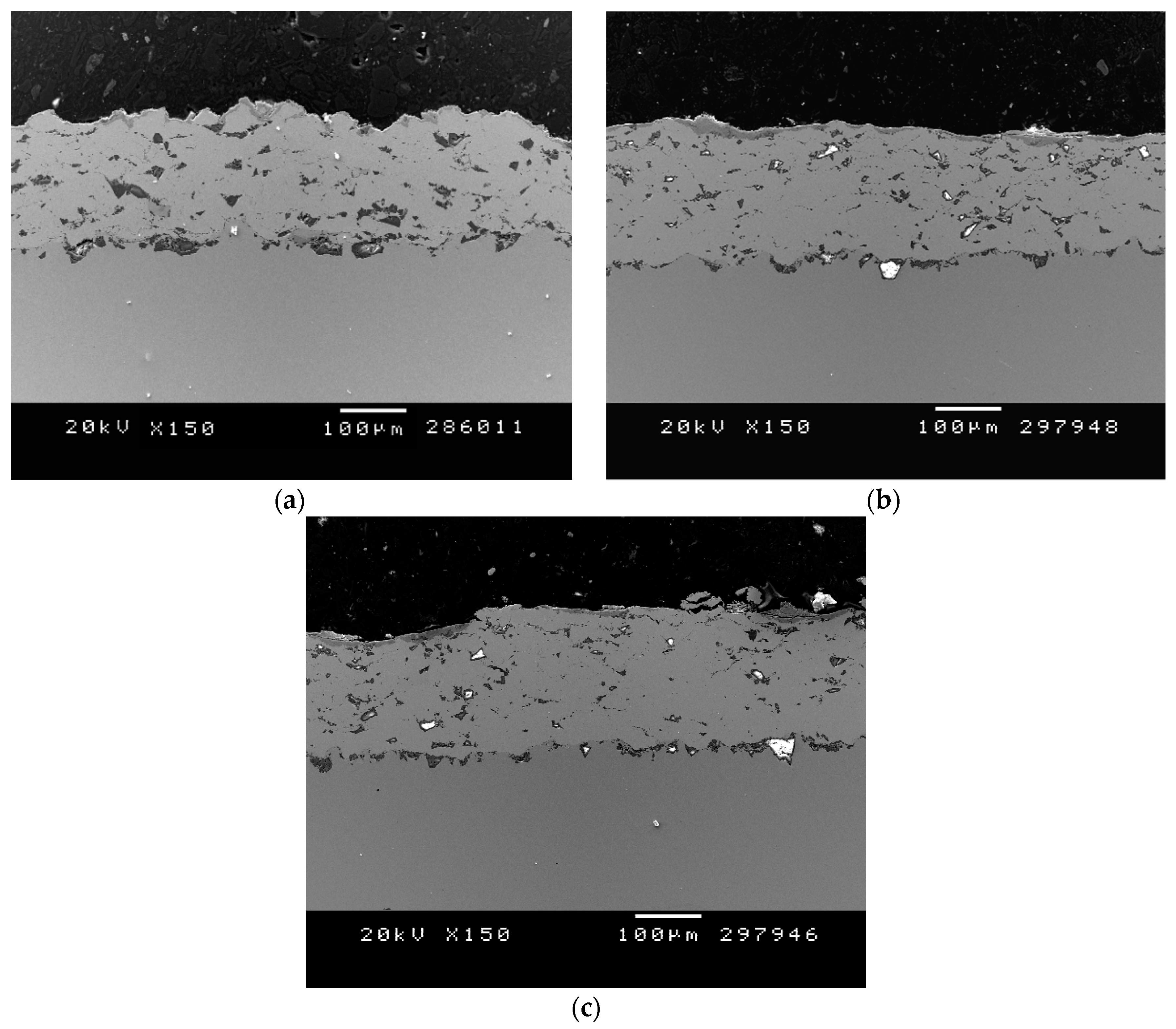
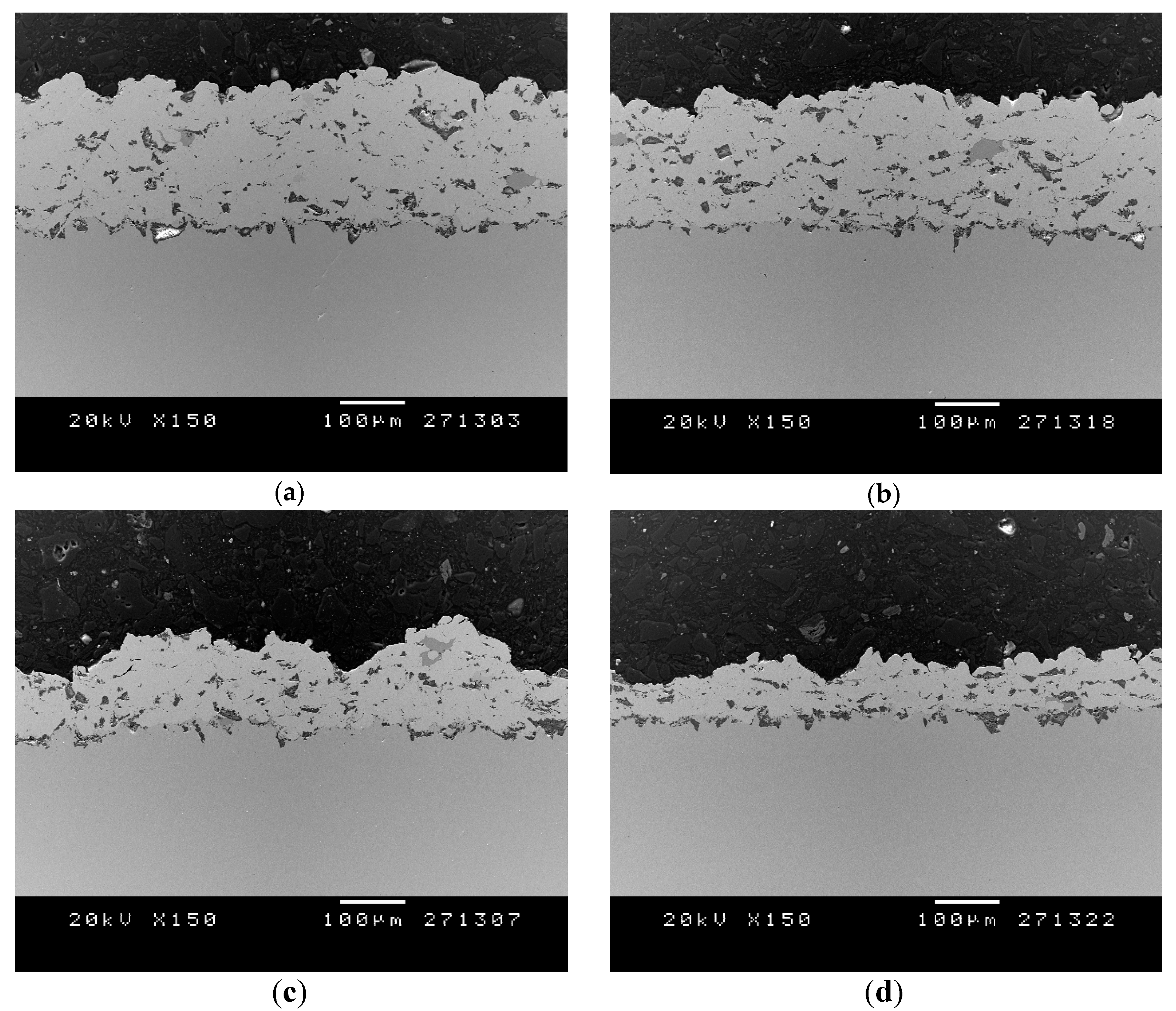
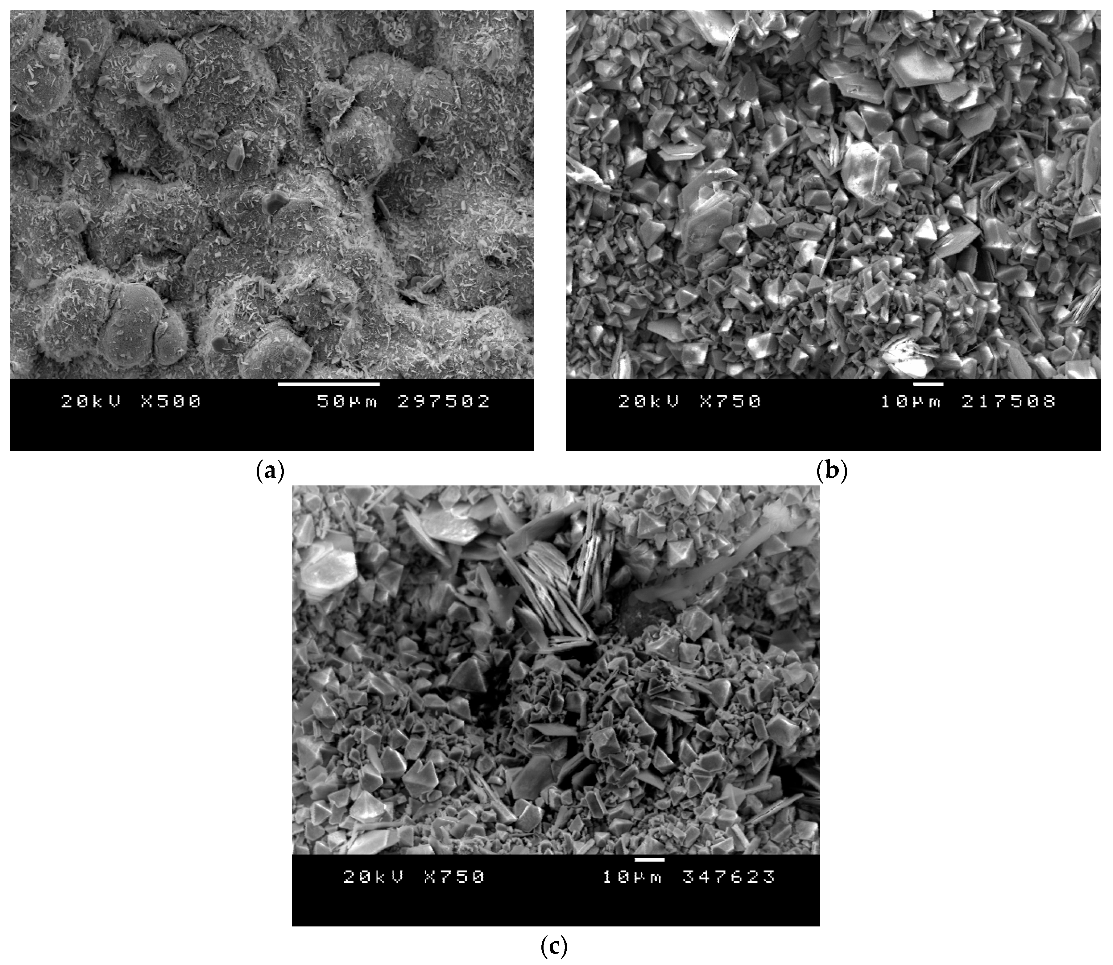
3.2. Structural Coating Characterization

Table 2 presents the four coating thicknesses, while Figure 2 shows SEM cross-sections of the corresponding deposited coatings obtained by using the differing alumina content. The coatings presented no delamination and good anchoring to the substrate, probably due to activation of the surface through co-spraying the alumina particles, which is known to decrease the delay time for particle attachment by cleaning and roughening the surface [25,26].
The coating thickness was observed to decrease when increasing the alumina content, indicating lower deposition efficiency at such levels, which might be attributed to an erosion effect on the previous layers in coatings C and D and may not be favorable for proper metal–metal bonding. Some authors have actually used hard particles to remove oxidation and promote more metal bonds [28]. In the present case, however, this is not a problem for an alloy such as Inconel. In addition, the Inconel–alumina interfaces are smooth and without gaps; a good bonding is produced, as observed in Figure 2. However, metal–metal bonds are stronger than metal–ceramic bonds due to the chemical nature of bonding and, moreover, to the fact that, upon impact, Al2O3 particles are fractured [36], whereas Inconel625 particles are deformed due to adiabatic shear instability. This explains why, when increasing the alumina content, and despite compaction, the deposition efficiency is lower and the coatings are more heterogeneous. This could serve to determine a limit on the ceramic particle content, at the point where the coating structure becomes weaker.
Poza et al. [37] and Koivuoluto et al. [25] justified the use of alumina particles for cleaning the nozzle of the gun rather than as a reinforcement and they also found that decreasing the alumina content increased the coating thickness; therefore, the alumina densifies the structure but prevents the formation of so many metallic–metallic bonds. In our case, coatings C and D have much less thickness, but the alumina content does not seem to change significantly; we mainly discarded those coatings because of their heterogeneous roughness. Coating A is slightly thicker than B for the same reasons encountered by the former authors in Ni20Cr [25]. Regarding the micrographs, Figure 2a shows a lower ceramic particle content than is shown in Figure 2b, as expected. However, contrary to previous authors, since we were seeking a coating with improved mechanical properties, B seems to be more suitable. The use of a laser treatment has also been justified as improving the coating structure following less nozzle damage [37].
Figure 3a shows the coating–substrate interface, where many alumina particles can be observed. Figure 3b shows the good cohesion between alumina particles and the metal Inconel matrix; no gaps were observed along such interfaces.

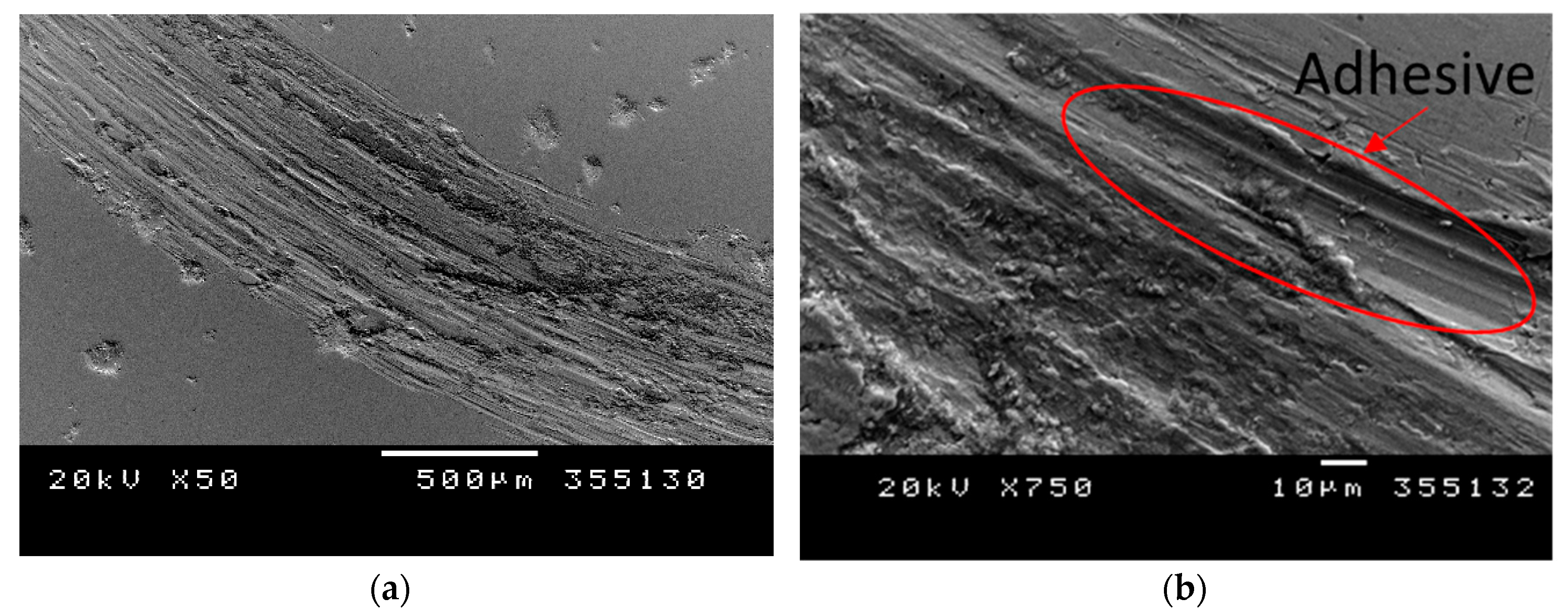
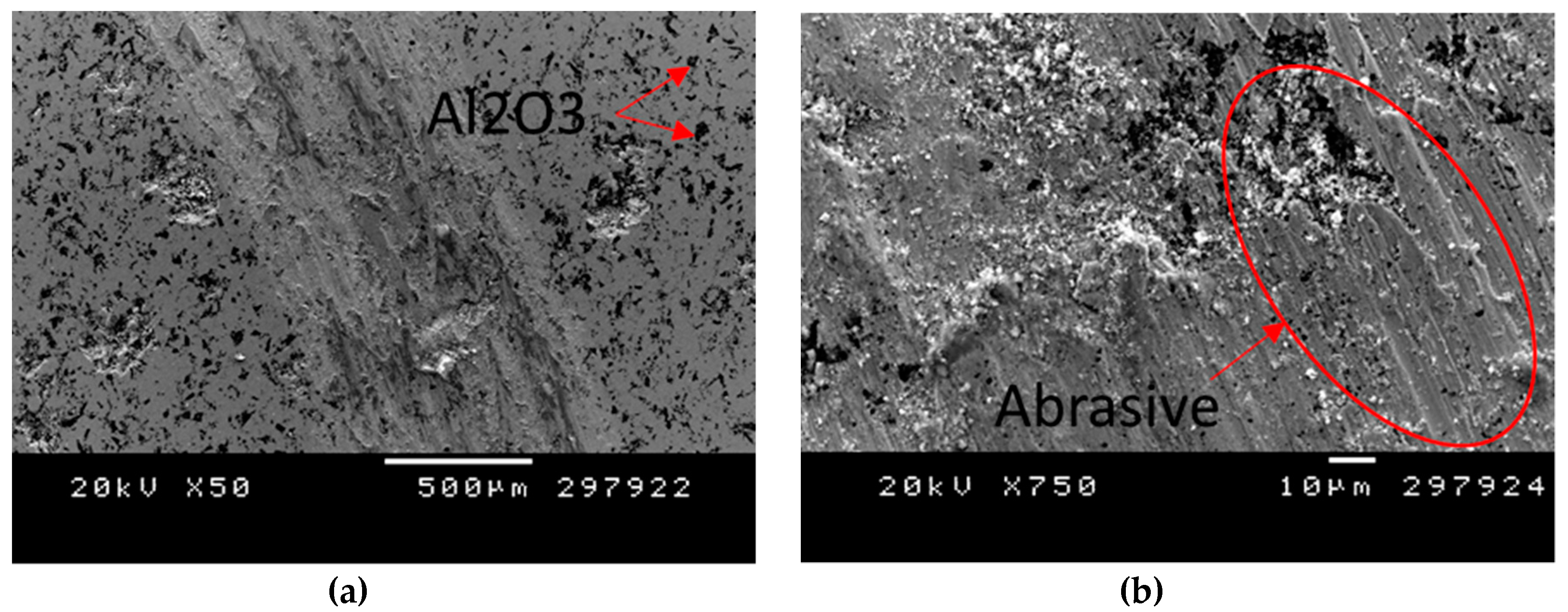
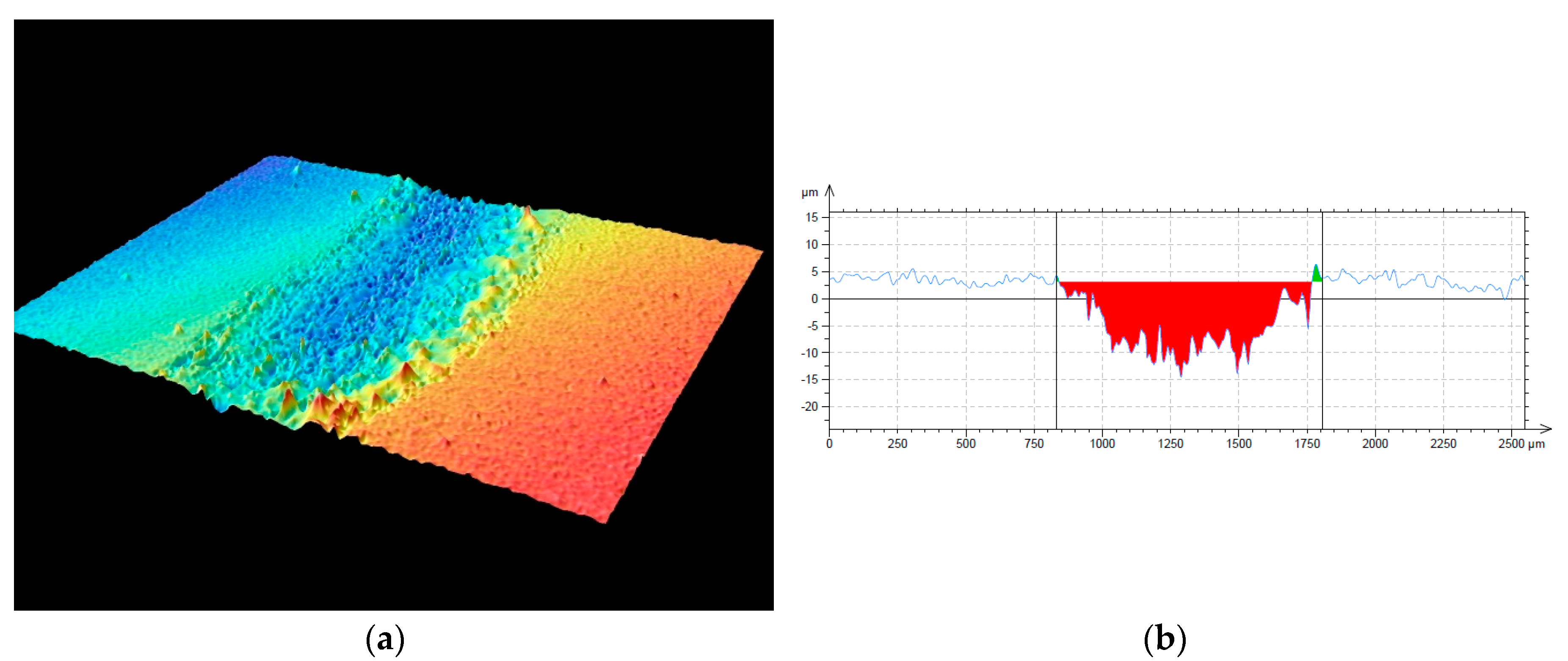
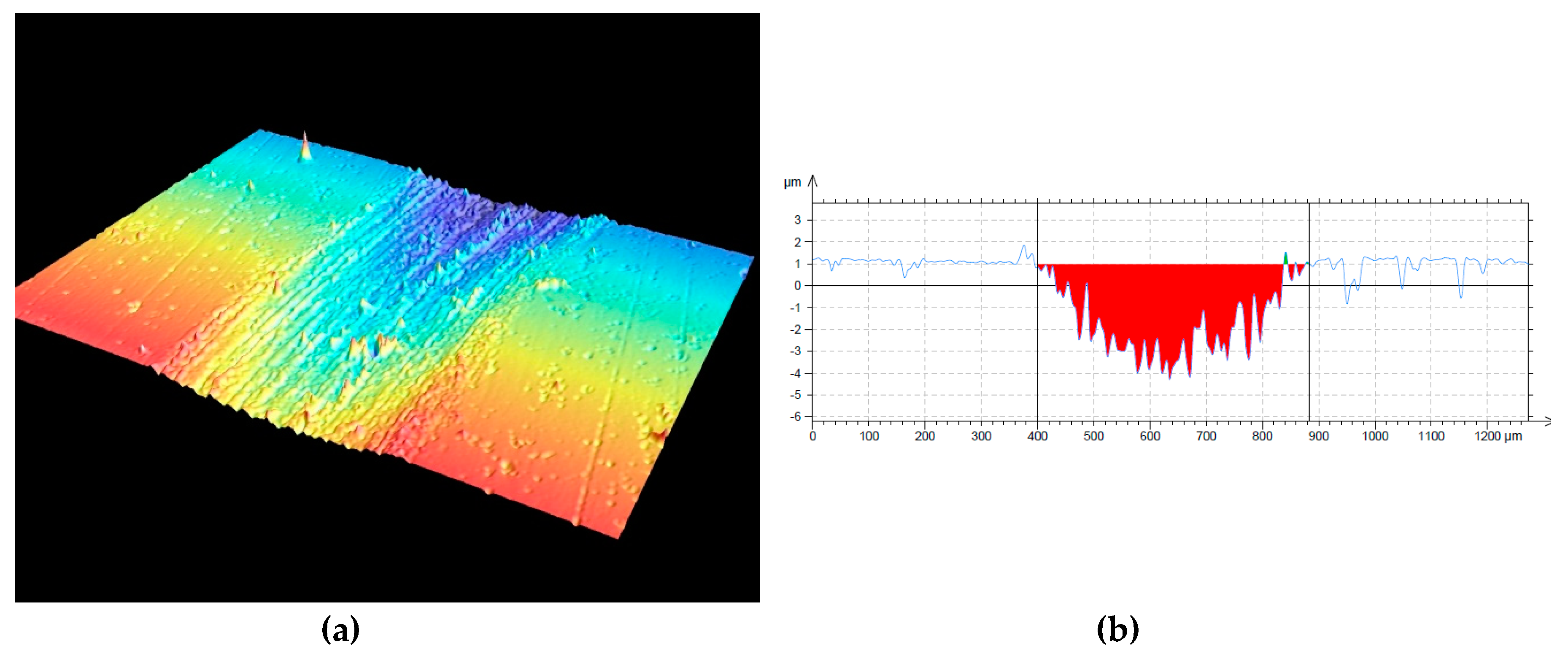
3.3. Mechanical and Tribological Properties

For further characterization, coating B was selected, exhibiting hardness values as high as 585 ± 56 HV0.3, which is more than double the value for the bulk material (Table 3). Its bond strength was found to be 26.8 ± 3.8 MPa and the coating failed at the interface with the substrate, which might be due to the presence of the alumina particles preventing the proper metal–metal bond between the Inconel particles and the substrate.
Wear resistance results for coating B in comparison to a bulk material can also be found in Table 2. The improvement in the abrasive wear rate can be associated with increased hardness (approximately 160%) resulting from spraying the powder through a CGS process and from the alumina particle reinforcement, as elucidated by the relationship between hardness and volume loss in the Archard general equation for wear [38].
While the friction coefficient values are analogous for both, the wear rate of the reinforced coating is one magnitude lower than that of the bulk material. The coating wear rate values are similar to those of Ni-based HVOF coatings tested under the same conditions [39].
Figure 4 and Figure 5 show the 3D and 2D profiles of the bulk Inconel and Inconel–Al2O3 coatings, respectively. Figure 5a reveals visible scarring along the direction of the sliding movement, indicating that abrasive wear is taking place, without the need to examine surface morphology. In Figure 4a, by contrast, it is not so evident. The 2D profiles illustrate that the wear track on the coating (Figure 5b) is not as wide and deep as on the bulk material (Figure 4b).
Figure 6 and Figure 7 show the wear track morphologies obtained after the sliding friction wear test for Inconel bulk and Inconel + alumina coatings, respectively. The plowing observed on the bulk Inconel may result from the abrasive grooving that occurs when the hard carbide particles of the cemented carbide ball penetrate to the softer Inconel; also, partial adhesive mechanism was observed in the border of plowing. Other abrasive mechanisms may be observed on ductile materials such as micro-cutting or wedge formation. In the cutting mode, long, curled ribbon-like wear particles are typically formed and low friction assists in this wear mode, whereas in the wedge-forming mode, a wedge-like wear particle is formed at the tip of the grooving asperity and stays there, working as a kind of built-up wedge to continue grooving. In the plowing mode, no wear particle is generated by a single sliding pass and only a shallow groove is formed. Repeated sliding and accumulation of plastic flow at the surface is necessary for the generation of wear particles.
Concerning the alumina-reinforced coating, the abrasive mode is highly affected by the pull out of the alumina particles, which remain entrapped between the sliding surfaces, get fractured, and generate an additional three-body abrasive wear (Figure 7b). Spencer et al. observed a change from adhesive-abrasion wear to pure abrasion when alumina content was increased [26], leading to more uniform friction coefficients and lower wear rates.
H.Y. Al-Fadhli et al. [31] exposed the HVOF Inconel625 coating to erosion–corrosion conditions and found that it exhibited excellent resistance, as it was not highly affected by the type of substrate material. Once the impinging fluid attacked the substrate material in the region below the coating, it resulted in a catastrophic failure in the coating. This was particularly true for substrate material consisting of carbon steel. The coating was found to be highly sensitive to the presence of sand particles in the impinging fluid [32]. In the present case study, the abrasive wear resistance of the Inconel bulk material was doubled by producing the reinforced coating. This effect, added to good oxidation and corrosion resistance, would be an important improvement in this field.

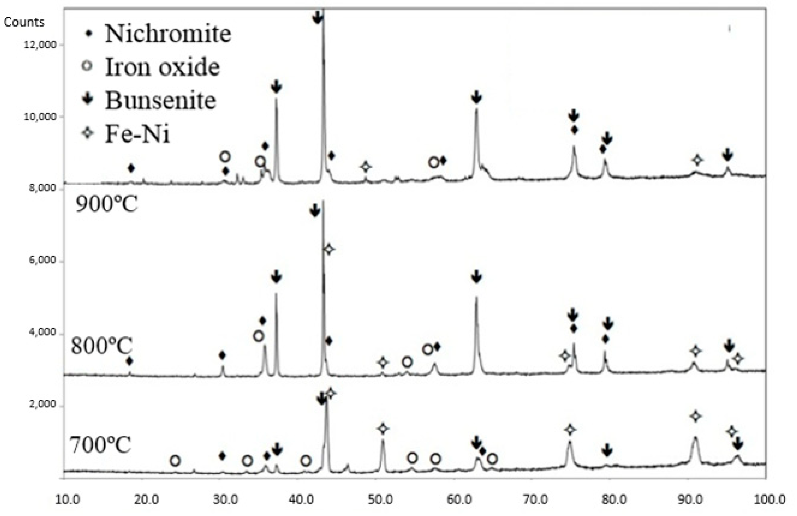
3.4. Oxidation Resistance

Three different temperatures (700, 800 and 900 °C) were tested over 72 h for the oxidation resistance studies. Cross-sections and top surfaces of the coatings were studied to determine the oxidation and possible formation of protective layers. Figure 8 shows that the coatings remained fairly intact at the three temperatures, with no coating thickness reduction and with a thin oxide layer on the top. This indicates that such a layer is protective and that particle cohesion within the coating is good enough; otherwise, the oxidizing atmosphere would have attacked the steel substrate.
Figure 9 shows the morphology of oxides produced on the coatings’ surface when oxidized at 700, 800, and 900 °C, over 72 h.
According to the X-ray diffractograms, these correspond to the oxides’ nichromite and bunsenite phases (Figure 10). Bunsenite is observed to grow rapidly, according to its peak intensities, with increasing temperature.

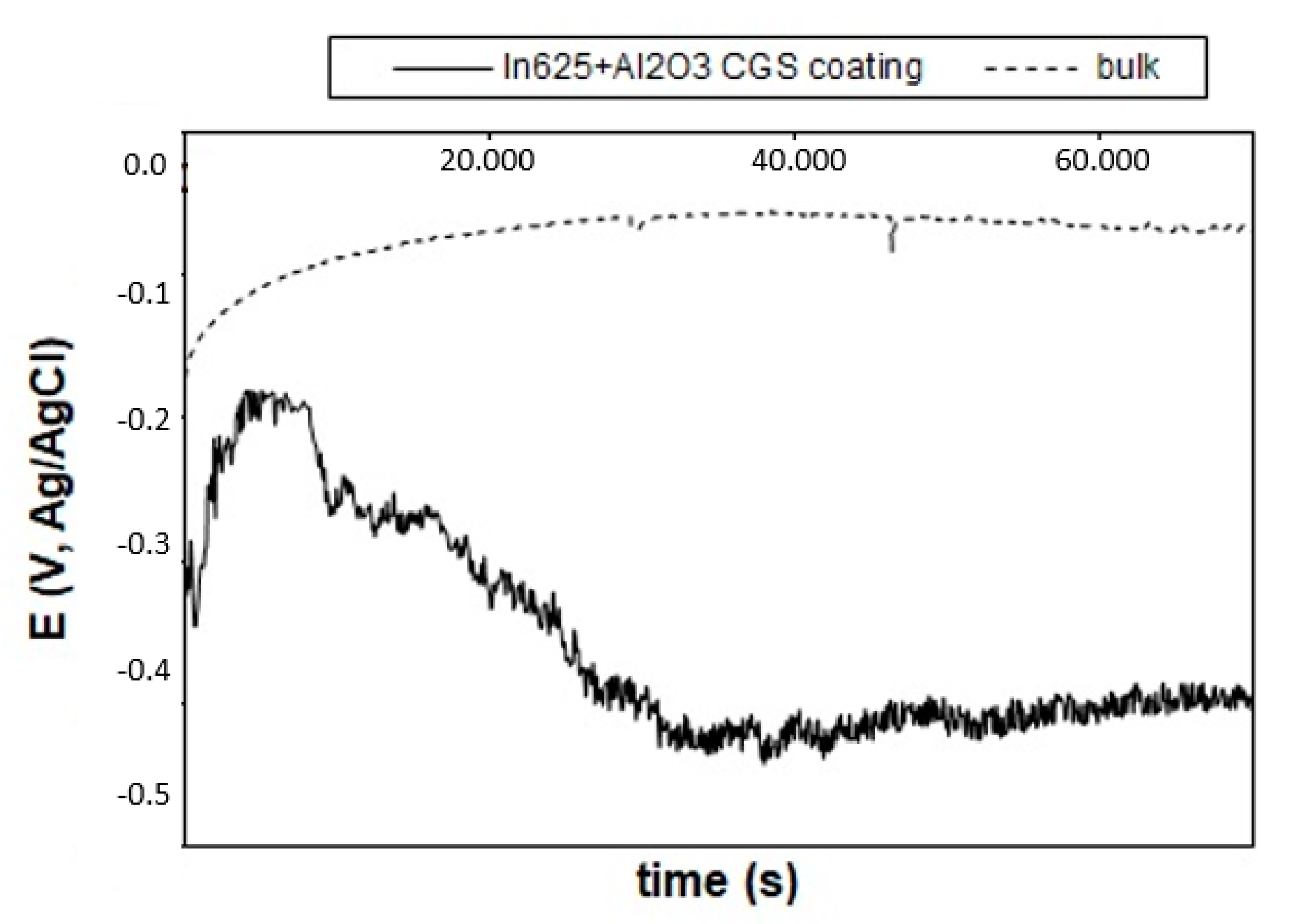
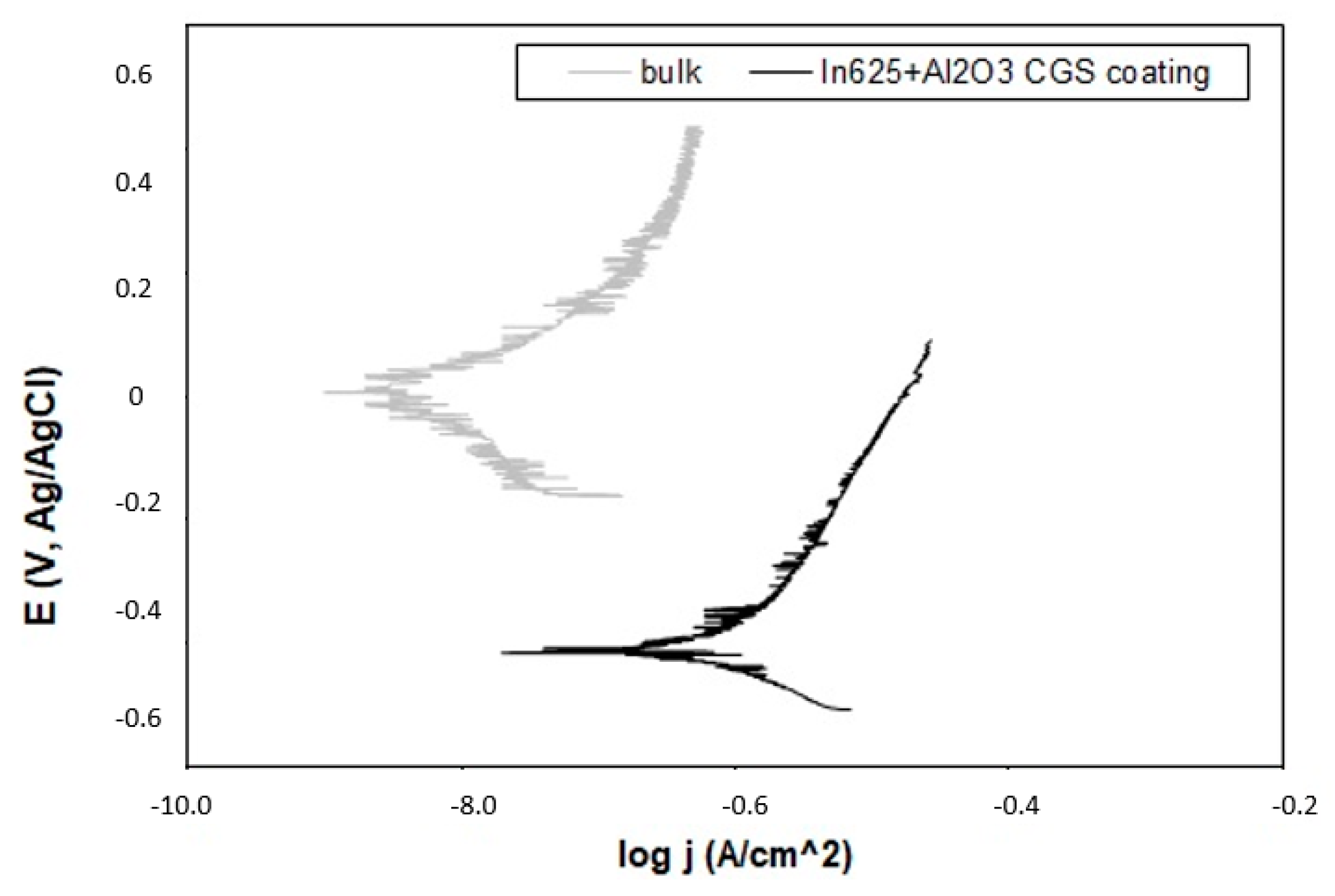
3.5. Corrosion Resistance

The electrochemical studies in 3.5% NaCl solution for the bulk alloy and the coating were also performed for the comparison of corrosion performance. Figure 11 illustrates the evolution of the open circuit potential, where the bulk stabilizes quite early on at values around −70 mV, whereas the cold-gas-sprayed coating starts with a similar trend as the bulk but decreases afterwards to less noble potentials at around −400 mV, indicating some penetration of the electrolyte after 2 h of immersion time.
Table 4 shows the corrosion potential and the corrosion current density values extracted from the Tafel curves (Figure 12). It can be seen that the corrosion intensity differs by one order of magnitude. Thus, it seems that the coating corrodes at a higher rate than the bulk material. This can be explained as follows: the bulk sample exhibited a very high impedance, attributed to the presence of a passivation layer over the whole exposed surface, whereas the Inconel particles may have promoted the rupture of such a layer upon impact, leaving fresh interfaces more apt to corrode. Depending on the reliability of the metallurgical bonding between Inconel–Inconel particles and the non-metallurgical bonding between alumina–Inconel particles, the path of the electrolyte through these fresh interfaces will be more or less favorable for its access to the substrate. However, the Ecorr values indicate that steel corrosion is not taking place. These values show similar corrosion resistance to those reported by Liu et al. [40] in relation to HVOF Inconel + WC coatings with the highest amount of WC and without thermal treatment, exposed to analogous corrosion conditions.

4. Conclusions

Cold gas spray has proven to be a successful process for producing alumina-reinforced Inconel625 coatings up to approximately 30 wt.% Al2O3 content, obtaining a homogeneously distributed and well-embedded alumina reinforcement within the coating and keeping a good cohesion among particles with an adhesive bond strength failure at 26.8 ± 3.8 MPa.
Hardness is increased to 585 ± 56 HV0.3, which influences the improvement of the abrasive and sliding wear resistance. A high-temperature oxidation performance is observed up to 900 °C, with no coating thickness reduction and with a thin oxide layer on the top. Additionally, although the wear performance is improved, the corrosion behavior evaluated in NaCl solution is less favored by the presence of the alumina particles, promoting the appearance of electrolyte paths.

Author Contributions

Conceptualization, S.D. and N.C.; methodology, N.C. and I.G.C.; validation, S.D., N.C., I.G.C., and A.S.; formal analysis, N.C.; investigation, N.C. and S.D.; writing—original draft preparation, N.C.; writing—review and editing, S.D. and A.S.; visualization, I.G.C.; supervision, S.D. and I.G.C.; funding acquisition, I.G.C. and S.D. All authors have read and agreed to the published version of the manuscript.

Funding

GENERALITAT DE CATALUNYA, grant number 2017SGR1777.

Conflicts of Interest

The authors declare no conflict of interest.

References

  1. ASM International. ASM Specialty Handbook: Nickel, Cobalt, and Their Alloys; ASM International: Novelty, OH, USA, 2001; Volume 38. [Google Scholar] [CrossRef]
  2. Vander Voort, G.F. Atlas of T-T Diagrams of Nonferrous Alloys; ASM International: Novelty, OH, USA, 1991; Volume 1, pp. 2–5. ISBN 978-0-87170-428-3. [Google Scholar] [CrossRef]
  3. Special Metal Corporation, Inconel Alloy 625. 2013, Volume: 625, pp. 1–28. Available online: https://www.specialmetals.com (accessed on 26 May 2020).
  4. Scrivani, A.; Ianelli, S.; Rossi, A.; Groppetti, R.; Casadei, F.; Rizzi, G. A Contribution to the Surface Analysis and Characterisation of HVOF Coatings for Petrochemical Application. Wear 2001, 250, 107–113. [Google Scholar] [CrossRef]
  5. Boudi, A.A.; Hashmi, M.S.J.; Yilbas, B.S. HVOF Coating of Inconel 625 onto Stainless and Carbon Steel Surfaces: Corrosion and Bond Testing. J. Mater. Process. Technol. 2004, 155–156, 2051–2055. [Google Scholar] [CrossRef]
  6. Planche, M.P.; Normand, B.; Liao, H.; Rannou, G.; Coddet, C. Influence of HVOF Spraying Parameters on In-Flight Characteristics of Inconel 718 Particles and Correlation with the Electrochemical Behaviour of the Coating. Surf. Coat. Technol. 2002, 157, 247–256. [Google Scholar] [CrossRef]
  7. Torrell, M.; Dosta, S.; Miguel, J.R.; Guilemany, J.M. Optimisation of HVOF Thermal Spray Coatings for Their Implementation as MSWI Superheater Protectors. Corros. Eng. Sci. Technol. 2010, 45, 84–93. [Google Scholar] [CrossRef]
  8. Edris, H.; Mccartney, D.G.; Sturgeon, A.J. Microstructural Characterization of High Velocity Oxy-Fuel Sprayed Coatings of Inconel625. J. Mater. Sci. 1997, 32, 863–872. [Google Scholar] [CrossRef]
  9. Cinca, N.; Barbosa, M.; Dosta, S.; Guilemany, J.M. Study of Ti Deposition onto Al Alloy by Cold Gas Spraying. Surf. Coat. Technol. 2010, 205, 1096–1102. [Google Scholar] [CrossRef]
  10. Assadi, H.; Kreye, H.; Gärtner, F.; Klassen, T. Cold Spraying—A Materials Perspective. Acta Mater. 2016, 116, 382–407. [Google Scholar] [CrossRef] [Green Version]
  11. Cavaliere, P.; Silvello, A.; Cinca, N.; Canales, H.; Dosta, S.; Garcia Cano, I.; Guilemany, J.M. Microstructural and Fatigue Behavior of Cold Sprayed Ni-Based Superalloys Coatings. Surf. Coat. Technol. 2017. [Google Scholar] [CrossRef]
  12. Silvello, A.; Cavaliere, P.; Rizzo, A.; Valerini, D.; Dosta Parras, S.; Garcia Cano, I. Fatigue Bending Behavior of Cold-Sprayed Nickel-Based Superalloy Coatings. J. Therm. Spray Technol. 2019. [Google Scholar] [CrossRef] [Green Version]
  13. Assadi, H.; Schmidt, T.; Richter, H.; Kliemann, J.O.; Binder, K.; Gärtner, F.; Klassen, T.; Kreye, H. On Parameter Selection in Cold Spraying. J. Therm. Spray Technol. 2011, 20, 1161–1176. [Google Scholar] [CrossRef]
  14. Rokni, M.R.; Nutt, S.R.; Widener, C.A.; Champagne, V.K.; Hrabe, R.H. Review of Relationship Between Particle Deformation, Coating Microstructure, and Properties in High-Pressure Cold Spray. J. Therm. Spray Technol. 2017, 26, 1308–1355. [Google Scholar] [CrossRef]
  15. Cavaliere, P.; Silvello, A. Processing Parameters Affecting Cold Spay Coatings Performances. Int. J. Adv. Manuf. Technol. 2014. [Google Scholar] [CrossRef]
  16. Chaudhuri, A.; Raghupathy, Y.; Srinivasan, D.; Suwas, S.; Srivastava, C. Microstructural Evolution of Cold-Sprayed Inconel625 Superalloy Coatings on Low Alloy Steel Substrate. Acta Mater. 2017, 129, 11–25. [Google Scholar] [CrossRef]
  17. Fantozzi, D.; Matikainen, V.; Uusitalo, M.; Koivuluoto, H.; Vuoristo, P. Chlorine-Induced High Temperature Corrosion of Inconel 625 Sprayed Coatings Deposited with Different Thermal Spray Techniques. Surf. Coat. Technol. 2017, 318, 233–243. [Google Scholar] [CrossRef]
  18. Azarmi, F.; Sevostianov, I. Comparative Micromechanical Analysis of Alloy 625 Coatings Deposited by Air Plasma Spraying, Wire Arc Spraying, and Cold Spraying Technologies. Mech. Mater. 2020, 144, 103345. [Google Scholar] [CrossRef]
  19. Marinescu, I.; Huong, Y.A.N.; Liu, E. Additive Manufacturing of Inconel625 Superalloy parts via high pressure cold spray. In Proceedings of the 3rd International Conference on Progress in Additive Manufacturing (Pro-AM 2018), Singapore, 14–17 May 2018; pp. 433–438. [Google Scholar] [CrossRef]
  20. Sova, A.; Grigoriev, S.; Okunkova, A.; Smurov, I. Potential of Cold Gas Dynamic Spray as Additive Manufacturing Technology. Int. J. Adv. Manuf. Technol. 2013, 69, 2269–2278. [Google Scholar] [CrossRef]
  21. Levasseur, D.; Yue, S.; Brochu, M. Pressureless Sintering of Cold Sprayed Inconel 718 Deposit. Mater. Sci. Eng. A 2012, 556, 343–350. [Google Scholar] [CrossRef]
  22. Singh, R.; Schruefer, S.; Wilson, S.; Gibmeier, J.; Vassen, R. Influence of Coating Thickness on Residual Stress and Adhesion-Strength of Cold-Sprayed Inconel 718 Coatings. Surf. Coat. Technol. 2018, 350, 64–73. [Google Scholar] [CrossRef]
  23. Luo, X.T.; Yao, M.L.; Ma, N.; Takahashi, M.; Li, C.J. Deposition Behavior, Microstructure and Mechanical Properties of an in-Situ Micro-Forging Assisted Cold Spray Enabled Additively Manufactured Inconel 718 Alloy. Mater. Des. 2018, 155, 384–395. [Google Scholar] [CrossRef]
  24. Pérez-andrade, L.I.; Gärtner, F.; Villa-vidaller, M.; Klassen, T.; Muñoz-saldaña, J. Surface & Coatings Technology Optimization of Inconel718 Thick Deposits by Cold Spray Processing and Annealing. Surf. Coat. Technol. 2019, 378, 124997. [Google Scholar] [CrossRef]
  25. Koivuluoto, H.; Vuoristo, P. Effect of Ceramic Particles on Properties of Cold-Sprayed Ni-20cr+ Al2O3 Coatings. J. Therm. Spray Technol. 2009, 18, 555–562. [Google Scholar] [CrossRef]
  26. Spencer, K.; Fabijanic, D.M.; Zhang, M.X. The Use of Al-Al2O3 cold Spray Coatings to Improve the Surface Properties of Magnesium Alloys. Surf. Coat. Technol. 2009. [Google Scholar] [CrossRef]
  27. Koivuluoto, H.; Vuoristo, P. Effect of Powder Type and Composition on Structure and Mechanical Properties of Cu + Al2O3 Coatings Prepared by Using Low-Pressure Cold Spray Process. J. Therm. Spray Technol. 2010, 19, 1081–1092. [Google Scholar] [CrossRef]
  28. Irissou, E.; Legoux, J.G.; Arsenault, B.; Moreau, C. Investigation of Al-Al2O3 Cold Spray Coating Formation and Properties. J. Therm. Spray Technol. 2007, 16, 661–668. [Google Scholar] [CrossRef]
  29. Sansoucy, E.; Marcoux, P.; Ajdelsztajn, L.; Jodoin, B. Properties of SiC-Reinforced Aluminum Alloy Coatings Produced by the Cold Gas Dynamic Spraying Process. Surf. Coat. Technol. 2008, 202, 3988–3996. [Google Scholar] [CrossRef]
  30. Li, W.Y.; Zhang, C.; Liao, H.; Li, J.; Coddet, C. Characterizations of Cold-Sprayed Nickel-Alumina Composite Coating with Relatively Large Nickel-Coated Alumina Powder. Surf. Coat. Technol. 2008, 202, 4855–4860. [Google Scholar] [CrossRef]
  31. Al-Fadhli, H.Y.; Stokes, J.; Hashmi, M.S.J.; Yilbas, B.S. The Erosion-Corrosion Behaviour of High Velocity Oxy-Fuel (HVOF) Thermally Sprayed Inconel625 Coatings on Different Metallic Surfaces. Surf. Coat. Technol. 2006, 200, 5782–5788. [Google Scholar] [CrossRef]
  32. Guilemany, J.M.; Torrell, M.; Miguel, J.R. Study of the HVOF Ni-Based Coatings’ Corrosion Resistance Applied on Municipal Solid-Waste Incinerators. J. Therm. Spray Technol. 2008, 17, 254–262. [Google Scholar] [CrossRef]
  33. Sova, A.; Kosarev, V.F.; Papyrin, A.; Smurov, I. Effect of Ceramic Particle Velocity on Cold Spray Deposition of Metal-Ceramic Coatings. J. Therm. Spray Technol. 2011, 20, 285–291. [Google Scholar] [CrossRef]
  34. Haines, R. Richard Haines. Notes Queries 1902, s9-IX, 341–342. [Google Scholar] [CrossRef]
  35. Conshohocken, W. Standard Test Method for Wear Testing with a Pin-on-Disk Apparatus 1. Wear 2007, 5, 1–5. [Google Scholar]
  36. Koivuluoto, H. Microstructural Characteristics and Corrosion Properties of Cold-Sprayed Coatings; Tampere University of Technology: Tampere, Finland, 2010. [Google Scholar]
  37. Poza, P.; Múnez, C.J.; Garrido-Maneiro, M.A.; Vezzù, S.; Rech, S.; Trentin, A. Mechanical Properties of Inconel625 Cold-Sprayed Coatings after Laser Remelting. Depth Sensing Indentation Analysis. Surf. Coat. Technol. 2014, 243, 51–57. [Google Scholar] [CrossRef]
  38. Hutchings, I.; Shipway, P. Tribology: Friction and Wear of Engineering Materials, 2nd ed.; Butterworth-Heinemann: Oxford, UK, 2017; pp. 1–388. [Google Scholar]
  39. Zhang, D.; Harris, S.J.; McCartney, D.G. Microstructure Formation and Corrosion Behaviour in HVOF-Sprayed Inconel 625 Coatings. Mater. Sci. Eng. A 2003, 344, 45–56. [Google Scholar] [CrossRef]
  40. Liu, Z.; Cabrero, J.; Niang, S.; Al-Taha, Z.Y. Improving Corrosion and Wear Performance of HVOF-Sprayed Inconel 625 and WC-Inconel 625 Coatings by High Power Diode Laser Treatments. Surf. Coat. Technol. 2007, 201, 7149–7158. [Google Scholar] [CrossRef]
Figure 1. SEM free-surface images of (a) Inconel625 and (b) alumina powders.
Metals 10 01263 g001
Figure 2. SEM cross-sections of the Inconel + alumina coatings presented in Table 2: (a) A, (b) B, (c) C, and (d) D.
Metals 10 01263 g002
Figure 3. (a) Coating–substrate interface and (b) detail of the microstructure (bonding of an alumina particle embedded in the Inconel625 matrix).
Metals 10 01263 g003
Figure 4. (a) 3D and (b) 2D profiles of the bulk Inconel625 wear track, obtained using confocal microscopy.
Metals 10 01263 g004
Figure 5. (a) 3D and (b) 2D profiles of the bulk Inconel–Al2O3 wear track, obtained using confocal microscopy.
Metals 10 01263 g005
Figure 6. (a) SEM free-surface images of the wear track after the friction wear test on the bulk Inconel: general view of the wear track and (b) detailed magnification showing the adhesive wear mode.
Metals 10 01263 g006
Figure 7. (a) SEM free-surface images of the wear track after the friction wear test on the Inconel–Al2O3 coating: general view of the wear track and (b) detailed magnification showing the abrasive wear mode (b).
Metals 10 01263 g007
Figure 8. SEM cross-sections of the alumina-reinforced Inconel coating after 72 h of oxidation testing: (a) 700 °C, (b) 800 °C, and (c) 900 °C.
Metals 10 01263 g008
Figure 9. Oxide morphologies produced on the coating surfaces after the heat treatment at (a) 700 °C, (b) 800 °C, and (c) 900 °C.
Metals 10 01263 g009
Figure 10. X-ray diffraction of the coatings oxidized at 700, 800, and 900 °C, over 72 h.
Metals 10 01263 g010
Figure 11. Open circuit potential for the bulk alloy and the coating.
Metals 10 01263 g011
Figure 12. Potentiodynamic curves of the bulk alloy and the coating.
Metals 10 01263 g012
Table 1. Particle size distribution of (a) Inconel625 and (b) alumina powders.
(a) Inconel625(b) Alumina
0.375 μm to 2000 μm0.040 μm to 2000 μm
Volume100%μmVolume100%μm
Mean23.77μmMean60.31μm
Median24.18μmMedian71.54μm
SD1.230μmSD2.660μm
d1017.79μmd1036.07μm
d9030.97μmd90118.0μm
Table 2. Structural characteristics of the evaluated coatings.
TypeAl2O3 wt.%Thickness (μm)
A23.1191.3 ± 5.9
B30.8169.8 ± 22.7
C34.7132.7 ± 17.8
D46.280.1 ±17.4
Table 3. Tribological properties of the alumina-reinforced Inconel coating compared to Inconel625 bulk material. CGS, cold gas spray.
TypeHV0.3Abrasive Wear Rate (mm3/Nm)Friction Wear Rate (mm3/Nm)Friction Coefficient
Inconel625 bulk~2251.5 × 10−4 ± 1.2 × 10−51.13 × 10−4 ± 1.5 × 10−50.78 ± 0.02
Inconel + Al2O3 CGS coating585 ± 568.3 × 10⁻⁵ ± 9.7 × 10−61.26 × 10−5 ± 6.5 × 10−70.79 ± 0.01
Table 4. Corrosion parameters estimated from the potentiodynamic curves.
Bulk InconelCGS Coating
Ecorr (mV Ag/AgCl)−70−404
Icorr (µA/cm2)0.020.344

