Article

Dilution Ratio and the Resulting Composition Profile in Dissimilar Laser Powder Bed Fusion of AlSi10Mg and Al99.8

Materials Testing Institute (MPA), University of Stuttgart, Pfaffenwaldring 32, 70569 Stuttgart, Germany
*
Author to whom correspondence should be addressed.
Metals 2020, 10(9), 1222; https://doi.org/10.3390/met10091222
Submission received: 7 August 2020 / Revised: 2 September 2020 / Accepted: 4 September 2020 / Published: 10 September 2020
(This article belongs to the Special Issue 10th Anniversary of Metals: Metallurgy and Metal Technology)

Abstract

:
A variant of a hybrid manufacturing process combines the benefits of laser powder bed fusion (LPBF) and conventional manufacturing. Hybrid manufacturing can result in dissimilar material combinations which are prone to process errors. This study is motivated by the future application of a hybrid manufacturing variant and focusses on dissimilar aluminium alloys were hot cracks are the dominant process errors. A theoretical model was derived for the composition profile based on the dilution ratio known from fusion welding. The theory was validated with penetration depth measurements and energy-dispersive X-ray spectroscopy line scans on samples manufactured by LPBF (powder AlSi10Mg, building platform Al99.8 and line energies Pv−1 = 0.26–0.42 J·mm−1). A material combination with a low hot crack susceptibility was chosen to establish the theory. The results suggest that the dilution ratio is dependent on the penetration depth and the layer thickness. The used line energies result in a dilution ratio of 67–86% which results in 2–6 re-melted and mixed layers per added layer. A specific process design metric, the mixture height, is proposed to estimate the spatial effect of the dilution. The results can be used to adjust process parameters to lessen the effect of process errors in dissimilar hybrid manufacturing and increase mechanical performance.

Graphical Abstract

1. Introduction

The laser powder bed fusion (LPBF) process, also known as selective laser melting (SLM), can produce highly complex geometries at no extra manufacturing time. An additional benefit of LPBF is that the process parameters are adjustable in a wide parameter field. This allows reaching specific technological properties, namely, surface roughness or high density. The disadvantage of the LPBF process is its low built-up rate and the associated high costs of the machine. One way to surpass this limitation is welding of additive manufactured components to wrought components [1]. Another possibility is to build up on existing conventionally manufactured parts. This manufacturing method is a variant of hybrid manufacturing and could be applied in future applications to surpass the limitations of LPBF.
The here described hybrid manufacturing variant combines the design freedom of the LPBF process with the relatively lower costs of conventional manufacturing, for example by forging. In principle, the combination of both manufacturing processes in one manufacturing chain is possible. This is especially economically interesting for parts with simple base geometry and additional geometrically complex structures. For example, a disk or ring shaped structure with thin turbine blades on top.
Applying the described hybrid manufacturing variant can lead to dissimilar powder and building platform materials. The dissimilar combination can be further differentiated between dissimilar base alloy, for example a combination of an iron-based and an aluminium-based alloy, or dissimilar alloys, for example a combination of two different aluminium-based alloys. This study focusses on the combination of two different aluminium-based alloys. To illustrate the point, powder material and building platform generally have the same alloy composition. However, in hybrid manufacturing practice this is not always possible because of the narrow spectrum of available powder alloys-mainly AlSi10Mg is available for aluminium powder alloys-compared to wrought or casting aluminium alloys [2,3].
As it is known from fusion welding, dissimilar alloys can lead to specific process errors which deteriorate the mechanical performance. These process errors are related to the composition of the mixture and are for example hot cracks, cracks due to dissimilar thermal expansion, intermetallic phases and segregation [4] (pp. 134, 255, 272, 325). Hot cracks are of particular interest for dissimilar aluminium alloy combinations because aluminium alloy mixtures can have different hot crack susceptibility than their respective base alloys. Therefore, filler materials are used in fusion welding [5]. Pinto et al. [6] analysed different weld configurations, aluminium-based filler materials and dissimilar aluminium combination in fusion welding. They found that solidification cracking could be avoided by modifying the weld pool chemistry by using an appropriate filler material and dilution ratios. However, using filler powder materials in LPBF is not available to avoid these process errors.
Current studies in LPBF highlight the feasibility of dissimilar base alloy combinations, such as iron-based with nickel-based or aluminium-based and copper-based, for hybrid manufacturing methods. The results of these studies suggest the occurrence of the aforementioned errors. Hinojos et al. investigated 316L/IN718 and IN718/316L (powder-building platform) with electron beam powder bed fusion (EPBF) [7]. They found cracks in the combination of 316L/IN718 due to the dissimilar thermal expansion coefficients of the alloys. Furthermore, dissimilar welds with hot cracks and intermetallic phases were manufactured such as AlSi10Mg/UNS C18400 copper alloy [8] and Al/316L both with LPBF [9]. Cyr et al. performed LPBF with maraging steel powder on a tool steel building platform for a single set of parameters and tested the mechanical performance of the combination [10]. This combination might be prone to segregation and deterioration of corrosion resistance because of the difference in the steels composition. Lastly, Zhang et al. successfully manufactured a combination of AlSi12/AlSi20 with LPBF [11] without any prominent process errors. In conclusion, the mechanical performance of the combinations could be improved by adjusting the process parameters similar to fusion welding to achieve a specific dilution ratio which in turn could reduce the deterioration of the process errors.
The mechanical performance could be improved if the relation between process parameters and the composition profile is known. To achieve this goal, this study derives a model of the composition profile based on the dilution ratio for LPBF. The model is validated by LPBF experiments and microstructural characterisation. The investigated dissimilar aluminium alloys combination is AlSi10Mg/Al99.8 (powder/building platform). This combination was chosen because it is hypoeutectic. Therefore, discontinuities in the microstructure are avoided and the resulting composition profile can be analytically recorded. In addition, the combination is not prone to hot cracks and can be used to establish the theory without any problems during processing of the parts.
This study derives a theoretical model for the composition profile in dissimilar LPBF based on the dilution ratio known from fusion welding. The goal of this study is to validate the theoretical model with penetration depth measurements and energy-dispersive X-ray spectroscopy line scans on samples manufactured by LPBF (powder AlSi10Mg, building platform Al99.8). The results of this study can be applied for process design of the described hybrid manufacturing variant, for example forging combined with LPBF.

2. Materials and Methods

A dissimilar aluminium alloy combination for the powder and the building platform alloy was chosen. The powder material was a commercial AlSi10Mg powder and the building platform material was 99.8% pure aluminium. The chemical compositions in weight percent of the used materials are listed in Table 1 given by the supplier information.
The top and bottom surface of the building platform was face milled and finished to ensure parallel sides and a surface roughness equal to standard building platforms. This combination was chosen because of its good processability, i.e. low hot crack susceptibility. Furthermore, the binary composition of the combination avoids discontinuities in the microstructure and weld pool due to other alloying elements.
The commercial AlSi10Mg powder was gas atomized with nitrogen. Its powder density was 1.40 kg·m−3. The size distribution of the powder was (diameter quantile) d10 = 26.57 μm, d50 = 44.94 μm and d90 = 74.14 μm.
The geometry of the parts were 15 mm × 10 mm × 10 mm (height × width × depth) and were manufactured with a SLM Solutions 280 HL (SLM Solutions, Luebeck, Germany) LPBF machine by use of the AlSi10Mg powder on top of the 99.8% pure aluminium plate. All samples were produced in the same process without supportive structures in an argon atmosphere. The substrate heating was at Tbp = 150 °C. The focus diameter df = 80 μm the nominal laser power P = 350 W, the added layer thickness tadd = 50 μm and the hatch spacing hs = 170 μm were constant for all samples. A 67° hatch strategy was chosen. The laser scan speed v = 850–350 mm·s−1 was varied with a step size of 100 mm·s−1. The range of laser scan speeds is commonly used to process AlSi10Mg on the used SLM Solutions 280 HL LPBF machine and was obtained at prior screening experiments at Rosswag GmbH (Rosswag GmbH, Pfinztal, Germany). The process parameters were chosen to avoid any lack of fusion and to ensure a high penetration depth in the building platform. In total six samples were produced.
After manufacturing, the samples were sawed perpendicular to the build plate plane and prepared for the metallographic analysis. The metallographic analysis consisted of scanning electron microscopy (SEM) done with Auriga SEM system (Carl Zeiss AG, Oberkochen, Germany) and light microscopy (LM) done with a Z-502 LM system (Leica Microsystems, Wetzlar, Germany). The samples were electrochemically polished with a flow rate of 9 with 20 V for 20 s on a Struers LECTROPOL for SEM. The electrolyte used contained 90 mL distilled water with 730 mL ethanol, 100 mL 2-butoxyethanol and 78 mL perchloric acid. The centre of the samples were analysed with an energy-dispersive X-ray spectroscopy (EDX) (Carl Zeiss AG, Oberkochen, Germany) line parallel to the building direction. Five parallel EDX line scans (Figure 1a) were measured in the middle of each of the sample. The EDX parameters were: 500 points per line with a step size of 5 μm, an integration time of 800 ms and an acceleration voltage of 15 kV. The five measured EDX line scans were averaged in order to reduce any effects of the position of the line scan. Afterwards the averaged profiles were smoothed with the Savitzky–Golay filter (convolution coefficient of c = 5). The smoothing filter was used to obtain an averaged value over the heterogeneous microstructure without data loss (Figure 1b).
After the EDX measurements, the samples were polished and etched for the measurement of the weld penetration depth tdepth. For the etching a mixture with 60 mL H2O, 10 g NaOH and 5 g potassium ferry cyanide was used. The etch time was a few seconds long. After the preparation step the contours of the melt pools could be clearly differentiated under the light microscope, see Figure 2.
In the light microscope, a horizontal line on the building platform surface was manually aligned, then the weld penetration depth tdepth was measured in the middle of each sample at five different melt traces (i = 5) and the mean value and the minimum and maximum values of the weld penetration depth were calculated.

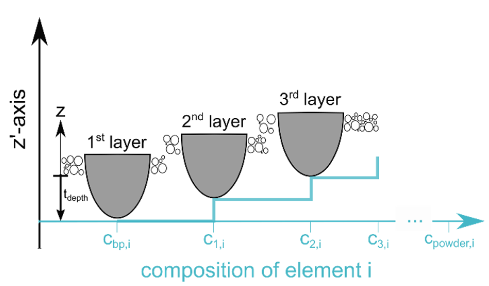
3. Theory Composition Profile Model for LPBF

The dilution ratio needs to be discussed in order to model the composition profile in LPBF. Welding dissimilar alloys is a common practice in fusion welding [4] (p. 275). The weld material composition cwm can be approximated with the dilution ratio Φ and the composition of the base material cbm and the added alloy cadd according to Equation (1).
c wm = Φ   c bm + ( 1 Φ )   c add
The LPBF process is comparable to fusion welding or deposition welding. A powder alloy is added on an existing building platform and then selectively melted. The two alloys are mixed depending on the area fractions. Figure 3 illustrates a single melt track for the first layer in LPBF.
The penetrated melt area Adepth is diluted with the added powder layer Aadd. The dilution ratio Φ for LPBF is expressed based on the definition of fusion welding in Equation (2) [12]:
dilution   ratio = penetrated   melt   area penetrated   melt   area + added   area = A depth A depth + A add
Equation (2) describes the dilution ratio as a function of the area fractions which are illustrated in Figure 3. The cross sectional areas cannot be identified unambiguously in LPBF because the melt tracks overlap. Therefore, a simplification is used. It is assumed that there is only a composition gradient in the z-direction (the building direction) because of the overlap of the melt tracks in one layer. Thus, the area ratios of Equation (2) can be expressed by the penetration depth tdepth and the added layer thickness tadd.
Φ = A depth A depth + A add t depth t depth + t add = 1 1 + t add t depth
Equation (3) describes the dilution ratio only as a function of the depth ratio t add / t depth . The dilution ratio can vary between 0 < Φ < 1 . The lower boundary is described by the minimum melt track depth. The melt track depth t = t add + t depth must be always greater than t add to ensure fusion. Therefore, the minimum condition to ensure fusion is t = t add . This leads to a negligible penetration depth t depth = 0 and to the minimum theoretical dilution ratio of Φ = 0 . The upper boundary is described by the extreme case that t depth   t add . Thus, the dilution ratio Φ 1 if the depth ratio t add / t depth is negligible small. In the here conducted experiments the processing parameters were chosen to avoid lack of fusion and ensure a high penetration depth in the building platform.
Next up, the model for the composition profile is presented. The composition cm,i of each mixed layers m and component i in the LPBF process is calculated analogue to the calculation of the weld material composition in fusion welding cwm. Figure 4 depicts the resulting stair case composition profile due to the re-melting of prior layers. The extend of the initial melt pool contour marks the origin of the z’-axis. The z’-axis will be used from now on to locate the mixed layers. The mixed layers are defined as the zones of the part that are equal in height to the layer thickness and are not re-melted by the subsequent melt tracks. The mixed layers are depicted in Figure 4 by the height difference between the melt pool tracks between the first, second and third layer.
The composition of the first mixed layer m = 1 can be described by the initial composition of the powder alloy c powder and of the building platform c bp and the dilution ratio Φ . The fraction of the component i   is given by Equation (4).
c 1 , i = Φ   c bp , i + ( 1 Φ )   c powder , i
The powder layers are added sequentially during the LPBF process until the specified part height is reached. Each subsequent layer is mixed with the layers below. Therefore, the resulting composition of the mixed layer m = 2 depends on the composition of the previous layer.
c 2 , i = Φ   c 1 , i + ( 1 Φ )   c powder , i
Combining Equations (4) and (5) yields the composition profile of the second mixed layer:
c 2 , i = Φ 2   c bp , i + ( 1 Φ 2 )   c powder , i
and Equation (6) can be generalised as a discrete limited growth to calculate the composition of the mixed layer m. The growth limit yields to lim m c m , i = c powder , i . The final model of the composition profile in LPBF is given by Equation (7).
c m , i = Φ m   c bp , i + ( 1 Φ m )   c powder , i

4. Results and Discussion

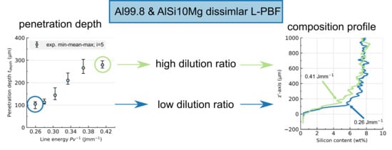
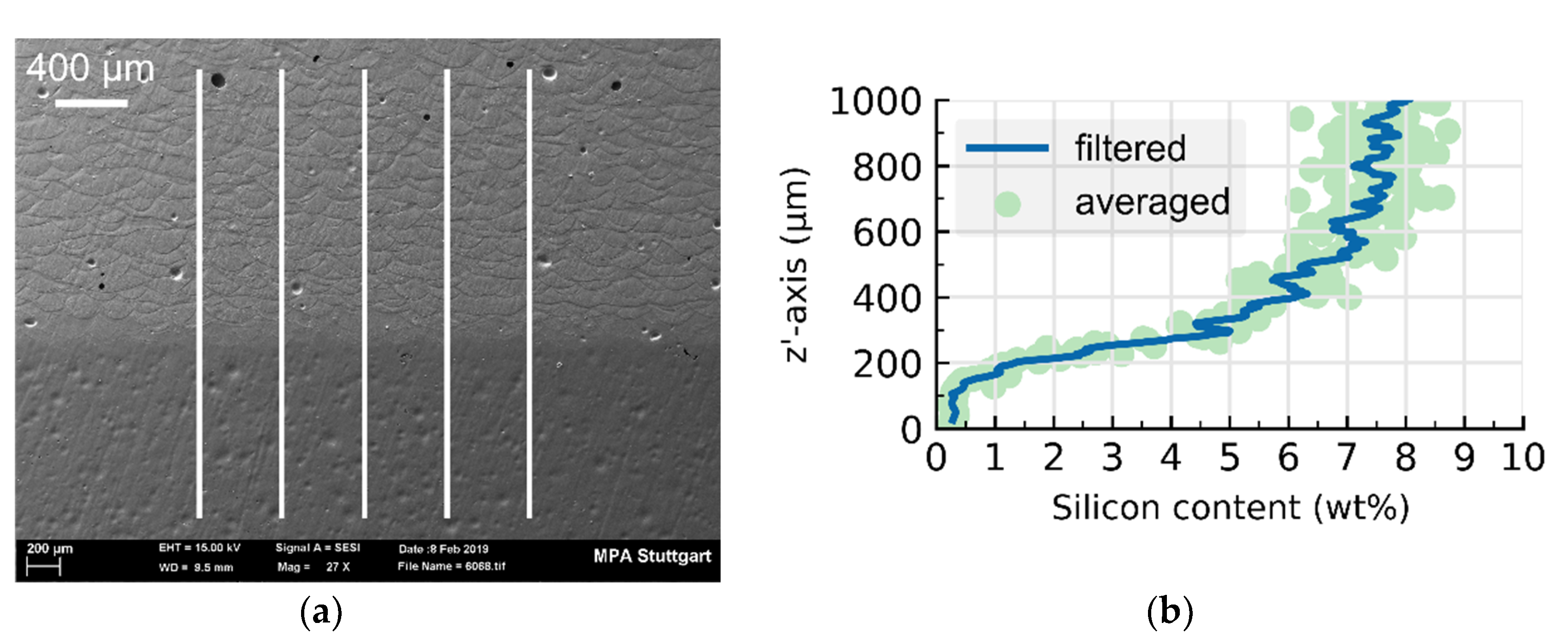
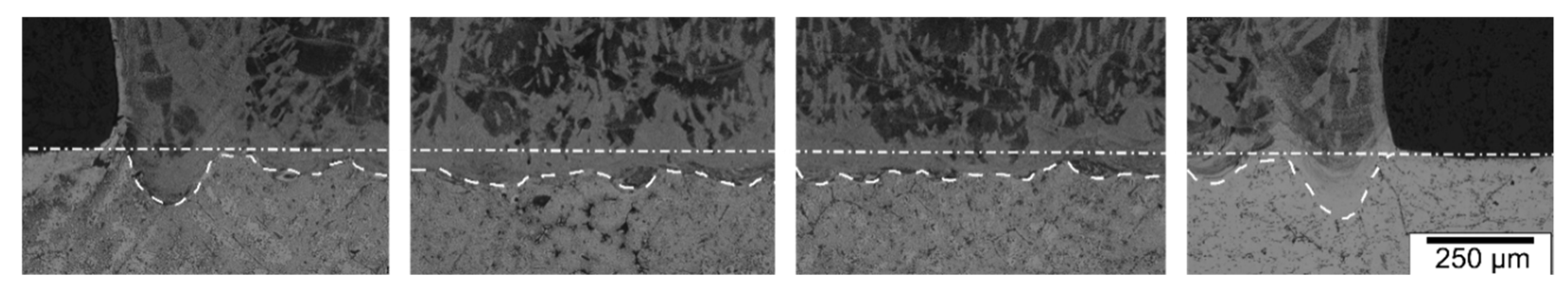
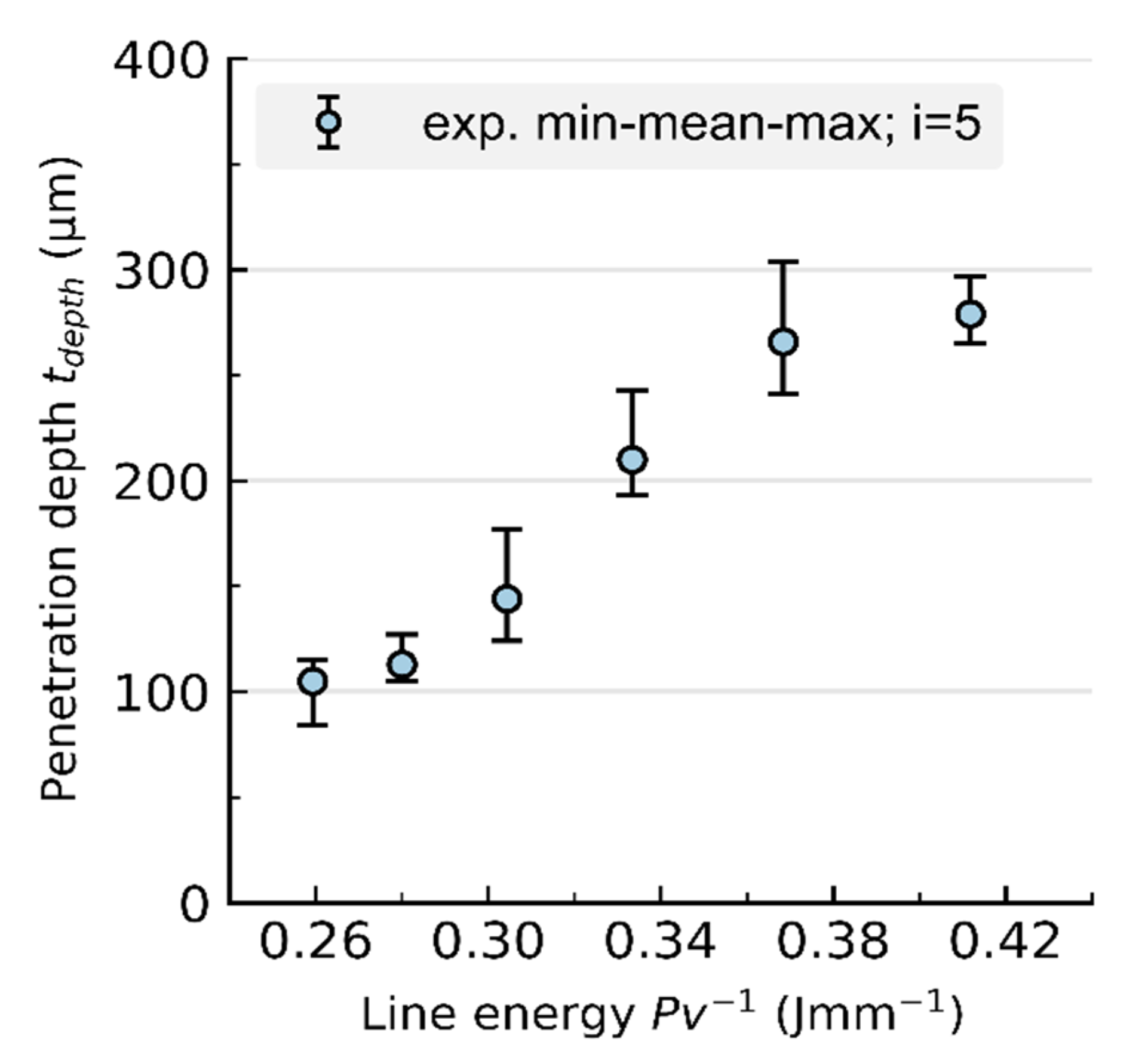
4.1. Influence of the Process Parameter on the Penetration Depth

Figure 5 shows the penetration depth as a function of the line energy Pv 1 . The depicted data points are the arithmetic mean of five experimental measurements of the penetration depth. The error bars represent the minimum and maximum experimentally determined penetration depth for each line energy. The higher the used line energy Pv 1 is the higher is the resulting penetration depth t depth . The minimal measured penetration depth is t depth , min 100   µ m . This is equal to m min 2 layers ( t add = 50   µ m ). The maximum measured penetration depth is t depth , max 300   µ m , which equals to m max 6 layers. This means that for each newly added powder layer m 2 6 layers are re-melted and mixed with the newly added powder layer depending on the used line energy. This results in dilution ratios between Φ 67 86 % according to Equation (3). The penetration depths measured in the cubic samples in this study ( P = 350   W ;   v = 850 1350   mm   s 1 ; Pv 1 = 0.26 0.41   J mm 1 ;   d f = 80   µ m ;   t add = 50   µ m ;   T bp = 150 ° C ) are in a similar range compared to single tracks found in literature [13,14,15].

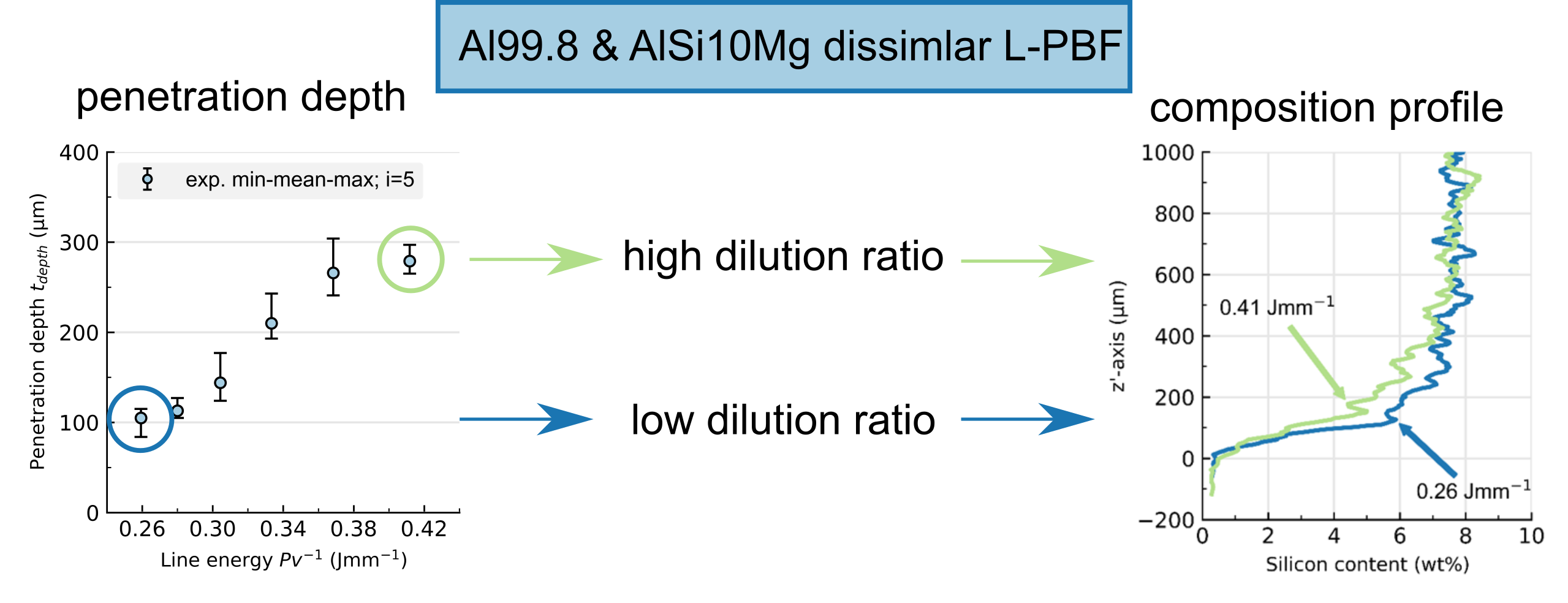
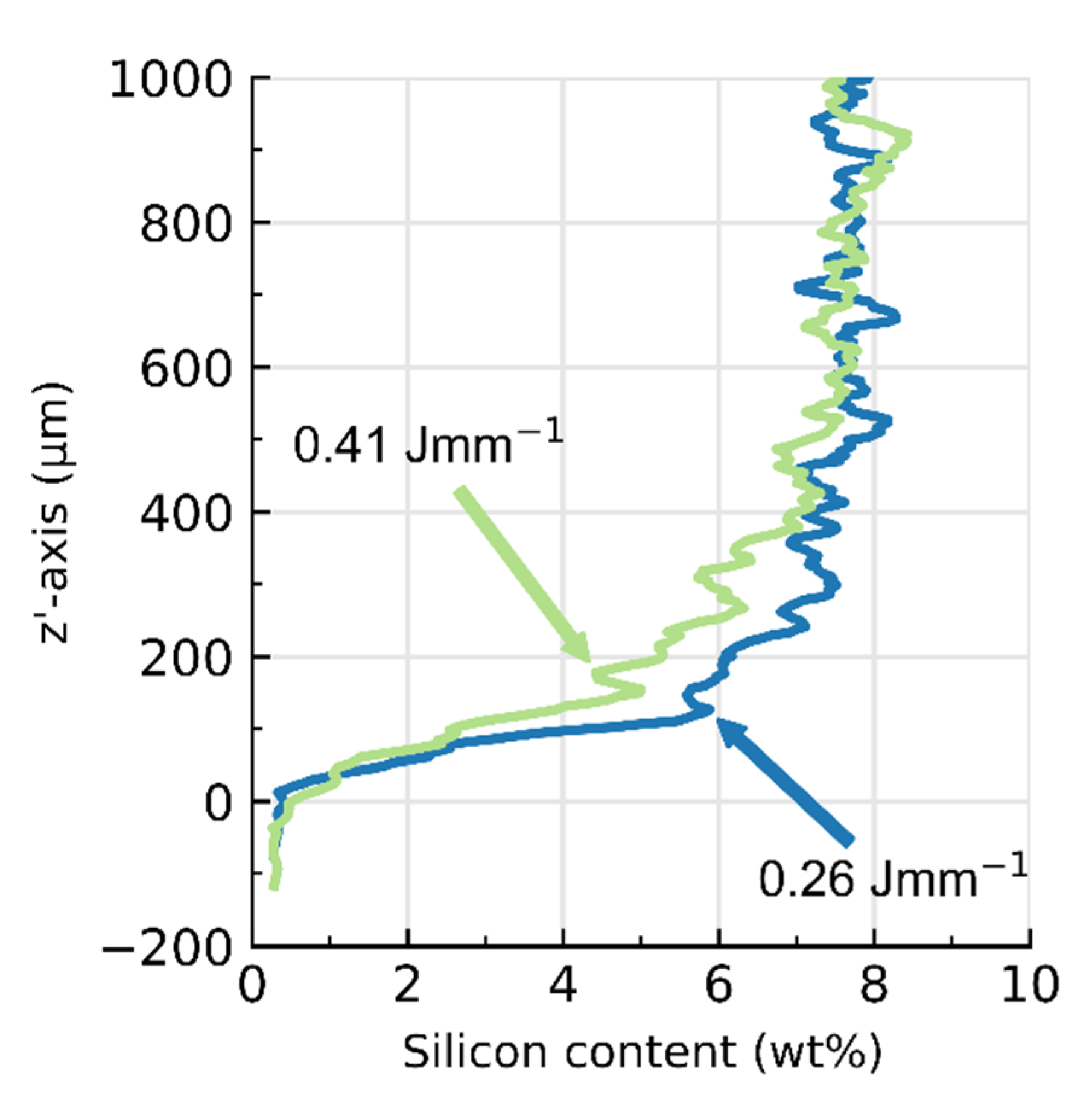
4.2. Influence of Process Parameter on the Composition Profile

Figure 6 shows the averaged and filtered EDX line scans of the minimum Pv 1 = 0.26   Jmm 1 and maximum line energy Pv 1 = 0.41   Jmm 1 . The measured trend corresponds to a limited growth, as described in the model Equation (7). Similar composition profiles were found in literature [9] and in gradient materials such as [16]. The minimum line energy leads to a low penetration depth and thus to a lower dilution rate. It is expected that the limit-approaching region is reached at lower heights because of the lower penetration depth. In contrast, the penetration depth increases and the limit-approaching region is reached after a higher number of added layers if the line energy increases. This means that a low line energy, or a low penetration depth, results in a lower influence of the building platform material in the building direction as it can be seen in Figure 6. The measured silicon content in the limit-approaching region c n , Si (   z   > 800   µ m ) is lower than the silicon content of the powder material c powder , Si 9.84   wt .   % . This deviation can have different causes. First, the EDX measurement is a semi-quantitative measurement thus only an approximation of the real composition profile. Second, the microstructure is heterogeneous ( α -aluminium phase and β -silicon). This leads to higher fluctuations depending on the position and size of the electron beam.

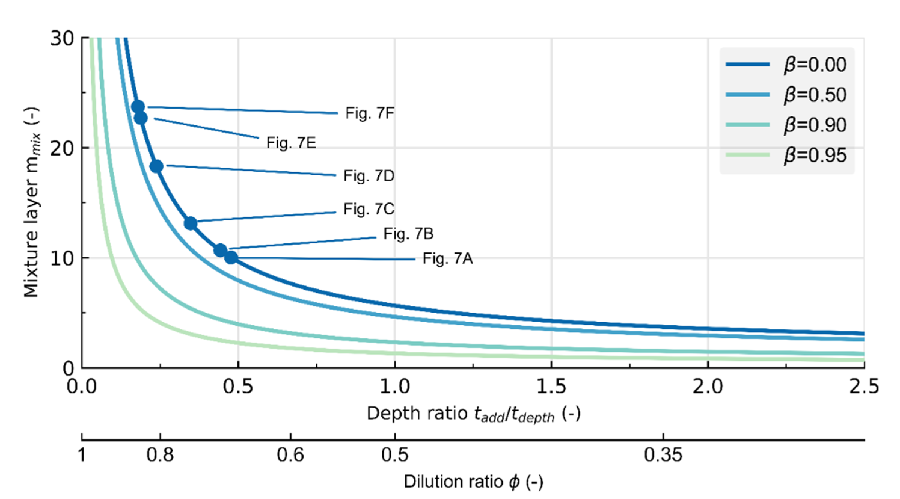
4.3. Comparison of Experiment and Model

The composition profile model, Equation (7) is applied and compared with the averaged and filtered composition profiles, see Figure 7. The applied model is discrete and describes the composition of a single diluted layer. Therefore, the calculated composition profile is represented as a staircase. The minimum and maximum measured values of the penetration depth are used to calculate the deviation of the model. Furthermore, the initial concentrations of the powder material c powder , Si and building platform c sp , Si were calculated from the averaged and filtered composition profile. The compositions c powder , Si and c sp , Si were averaged, respectively, over the first and last ten points of the composition profile. Moreover, the starting point of the first layer was chosen as the first point that exceeded the initial concentration of c powder , Si . Furthermore, it is assumed that the dilution ratio is independent of the composition and is constant for each set of process parameters.
The model describes the composition profile trend qualitatively. At lower line energies (Figure 7A–C), the model is within good agreement with the approximated composition profile. The greatest deviation is seen in (Figure 7E). The results suggest that the model is a reasonable good approximation for the composition profile.
The composition profile model can be used for improving hybrid manufacturing. It is shown that the penetration depth and the added layer thickness are the main influence factors. Both parameters can be adjusted by the highly adjustable LPBF process. For example, the penetration depth can be increased by increasing the line energy. This in turn alters the dilution ratio and affects the resulting composition profile. Subsequently, this has an effect on the process errors experienced in LPBF of dissimilar aluminium alloys. It would be useful to alter the process parameters specifically for the zone that is diluted. Afterwards the optimum parameters for the powder alloy could be chosen. However, the size of the region, in which the dilution affects the composition profile, is unknown.

4.4. Limitations of the Developed Theoretical Model

The here presented theoretical model described by Equation (7) takes the penetration depth and the layer thickness as well as the chemical composition of the powder and the building platform into account. The theoretical model is in good agreement with the experimental measured composition profile. However, the theoretical model is limited to an ideal mixture of the two materials in the melt pool of each layer. As it is known from fusion welding, macrosegregation within a weld pool is possible due to high welding speeds in electron or laser fusion welding [4] (pp. 255–257). The presented theoretical model does not consider the latter described behavior. Therefore, the here presented model is limited to the analysed laser scan speeds of v = 850 1350   mm   s 1 . Furthermore, the assumption of an ideal mixture is not valid if the material combination results into a miscibility gap. Lastly, the penetration depth can vary with increasing layers due to heating of the part during build up. This is also not taken into account in the presented model.

5. Implications for Process Design

In this section, the model is applied in order to derive the spatial effect of the diluted region. The mixture height h mix is proposed as a process design metric. It can be used to approximate the number of layers that are diluted with the building platform.
On the one hand, this could be useful for processing dissimilar aluminium alloys with LPBF. On the other hand, the here presented model and process characteristic could be beneficial to process dissimilar base alloys with LPBF, such as Al and 316L as Nguyen et al. [9] did. They found that with increasing line energy the failure of the joint occurred in earlier layers, which indicates that the dilution ratio between Al and Fe plays an important role as it is known from dissimilar fusion welding. Furthermore, the model could be beneficial for improving the combination of 316L/IN718 in EBM [7]. The results of Hinojos et al. suggest that the high composition gradient leads to a high gradient in the thermal expansion coefficient and increases the proclivity to cracks in the interface. One way to reduce the effect is to lower the composition gradient or to increase the mixture height. The applicability of the here presented model is not yet validated for different base materials. However, it could be used as an initial approach for further research.
It is assumed that the size of the dilution-affected region is described by the mixture height. The mixture height h mix is defined in this study as the height at which the composition profile reaches 98 %   ( α = 0.98 ) of the powder alloy composition. This leads to a known layer composition of c mix , i ( m = m mix ) = α c powder , i = 0.98 c powder , i . Applying this to Equation (7) results in Equation (8) which describes the desired mixture layer m mix . It is assumed that c powder , Si > c pb , i .
m mix = ln ( 1 α 1 c bp , i c powder , i ) 1 ln ( Φ )
The mixture height can be simply calculated by the thickness of the added layers h mix = m mix t add . In a special case, where the initial concentration c bp , i = 0 the mixture layer yields:
m mix = ln ( 1 α ) 1 ln ( Φ ) ;   c bp , i = 0
and is only a function of the dilution ratio ϕ . The Equation (9) is further generalised for the ratio of the initial compositions of the powder and building platform alloy β = c pb , i / c powder , i .
m mix = ln ( 1 α 1 β ) 1 ln ( Φ ) ;   β = c pb , i c powder , i
Figure 8 shows the influence of the dilution ratio and the depth ratio on the mixture layer according to Equation (10). An increased mixture layer leads to a flatter slope of the composition profile. In the current study, the mixture height varies between h mix 500 1500   µ m for a layer thickness of t add = 50   µ m . The mixture height can be used as a process design metric. For example, the process parameters can be adapted, in this case, for the initial 10 30 layers, where dilution affects the composition.

6. Conclusions

A model for the composition profile for hybrid manufacturing of dissimilar aluminium alloys with LPBF was derived. Al99.8 was used as the building platform material and AlSi10Mg as the powder material. The process parameters were chosen to avoid lack of fusion and ensure high penetration depth. The theoretical model was validated through averaged and filtered EDX and light microscopy measurements of the analysed dissimilar aluminium alloy parts. The influence factor of the dilution ratio is shown to depend solely on the penetration depth and the layer thickness according to Equation (3). It was found that the dilution ratio in the here conducted experiments (Pv−1 = 0.26–0.41 J·mm−1) were Φ 67 86 % . Furthermore, the number of layers re-melted per layer is between m = 2   6 layers. A process design metric, the mixture height h mix , was introduced to calculate the number of diluted layers that are affected. This metric allows to adjust the process parameters specifically for the diluted zone. The applicability of the model on dissimilar base materials, such as a combination of iron-based and aluminium-based alloys, must be investigated in further research.

Author Contributions

Conceptualization, M.W. and C.B.; methodology, C.B.; formal analysis, C.B.; investigation, C.B.; writing—original draft preparation, C.B.; writing—review and editing, M.W. and S.W.; supervision, M.W. and S.W. All authors have read and agreed to the published version of the manuscript.

Funding

This research received no external funding. This publication was supported by the Open Access Publishing Fund of the University of Stuttgart.

Acknowledgments

The authors gratefully acknowledge Gregor Graf (Rosswag GmbH, Pfinztal, Germany) and Jonas Koch (Rosswag GmbH, Pfinztal, Germany) for preparing the samples and Novelis Inc. for supplying the material for the building platform.

Conflicts of Interest

The authors declare no conflict of interest.

References

  1. Shribman, V.; Nahmany, M.; Levi, S.; Atiya, O.; Ashkenazi, D.; Stern, A. MP Welding of dissimilar materials: AM laser powder-bed fusion AlSi10Mg to wrought AA6060-T6. Prog. Addit. Manuf. 2020, 5, 171–181. [Google Scholar] [CrossRef]
  2. Ostermann, F. Anwendungstechnologie Aluminium; Springer: Berlin/Heidelberg, Germany, 2014; ISBN 978-3-662-43806-0. [Google Scholar]
  3. DIN EN 573-3, Aluminium and Aluminium Alloys—Chemical Composition and Form of Wrought Products—Part 3: Chemical Composition and Form of Products; German Version EN 573-3:2019. Available online: https://www.beuth.de/de/norm/din-en-573-3/307211401 (accessed on 2 September 2020).
  4. Kou, S. Welding Metallurgy, 2nd ed.; John Wiley and Sons: Hoboken, NJ, USA, 2003; ISBN 0471434914. [Google Scholar]
  5. Enz, J.; Kumar, M.; Riekehr, S.; Ventzke, V.; Huber, N.; Kashaev, N. Mechanical properties of laser beam welded similar and dissimilar aluminum alloys. J. Manuf. Process. 2017, 29, 272–280. [Google Scholar] [CrossRef]
  6. Pinto, L.A.; Quintino, L.; Miranda, R.M.; Carr, P. Laser welding of dissimilar aluminium alloys with filler materials. Weld. World 2010, 54, 333–341. [Google Scholar] [CrossRef]
  7. Hinojos, A.; Mireles, J.; Reichardt, A.; Frigola, P.; Hosemann, P.; Murr, L.E.; Wicker, R.B. Joining of Inconel 718 and 316 Stainless Steel using electron beam melting additive manufacturing technology. Mater. Des. 2016, 94, 17–27. [Google Scholar] [CrossRef] [Green Version]
  8. Sing, S.L.; Lam, L.P.; Zhang, D.Q.; Liu, Z.H.; Chua, C.K. Interfacial characterization of SLM parts in multi-material processing: Intermetallic phase formation between AlSi10Mg and C18400 copper alloy. Mater. Charact. 2015, 107, 220–227. [Google Scholar] [CrossRef]
  9. Nguyen, D.S.; Park, H.S.; Lee, C.M. Applying selective laser melting to join Al and Fe: An investigation of dissimilar materials. Appl. Sci. 2019, 9, 3031. [Google Scholar] [CrossRef] [Green Version]
  10. Cyr, E.; Asgari, H.; Shamsdini, S.; Purdy, M.; Hosseinkhani, K.; Mohammadi, M. Fracture behaviour of additively manufactured MS1-H13 hybrid hard steels. Mater. Lett. 2018, 212, 174–177. [Google Scholar] [CrossRef]
  11. Zhang, S.; Pan, M.; Jia, Y.; Yu, Z.; Sokkalingam, R.; Shi, X.; Ji, P.; Eckert, J.; Prashanth, K.G. Microstructure and Mechanical Properties of Al–(12-20)Si Bi-Material Fabricated by Selective Laser Melting. Materials 2019, 12, 2126. [Google Scholar] [CrossRef] [PubMed] [Green Version]
  12. Fahrenwaldt, H.J.; Schuler, V.; Twrdek, J. Praxiswissen Schweißtechnik; Springer: Berlin/Heidelberg, Germany, 2013; ISBN 9783658031404. [Google Scholar]
  13. Aversa, A.; Moshiri, M.; Librera, E.; Hadi, M.; Marchese, G.; Manfredi, D.; Lorusso, M.; Calignano, F.; Biamino, S.; Lombardi, M.; et al. Single scan track analyses on aluminium based powders. J. Mater. Process. Technol. 2018, 255, 17–25. [Google Scholar] [CrossRef]
  14. Nie, X.; Zhang, H.; Zhu, H.; Hu, Z.; Ke, L.; Zeng, X. Analysis of processing parameters and characteristics of selective laser melted high strength Al-Cu-Mg alloys: From single tracks to cubic samples. J. Mater. Process. Technol. 2018, 256, 69–77. [Google Scholar] [CrossRef]
  15. Matilainen, V.; Piili, H.; Salminen, A.; Syvänen, T.; Nyrhilä, O. Characterization of process efficiency improvement in laser additive manufacturing. Phys. Procedia 2014, 56, 317–326. [Google Scholar] [CrossRef] [Green Version]
  16. Campanelli, S.L.; Angelastro, A.; Signorile, C.G.; Casalino, G. Investigation on direct laser powder deposition of 18 Ni (300) marage steel using mathematical model and experimental characterisation. Int. J. Adv. Manuf. Technol. 2017, 89, 885–895. [Google Scholar] [CrossRef]
Figure 1. (a): Scanning electron microscopy (SEM) of the mixture zone orientated in building direction. Darker appearing material (bottom half) is the building platform, lighter AlSi10Mg (upper half). The five energy-dispersive X-ray spectroscopy (EDX) line scans are highlighted with white lines parallel to the building direction. (b): Comparison of averaged and filtered EDX profile section.
Metals 10 01222 g001
Figure 2. Etched cross sections of a sample. The dash-dot line marks the building platform surface and the dashed line indicates the penetration depth into the building platform. The penetration depth is the distance between building platform surface and the bottom of the melt track.
Metals 10 01222 g002
Figure 3. Equation (2) explained for the laser powder bed fusion LPBF process for the first layer of a single melt track.
Metals 10 01222 g003
Figure 4. Staircase composition profile is depicted of the mixed layers. Introduction of z’-axis which is shifted by the penetration depth. Composition change starts within the building plate.
Metals 10 01222 g004
Figure 5. Results of the light microscopy measurement of the penetration depth. Minimum, mean and maximum of i = 5 measurements are depicted for each line energy.
Metals 10 01222 g005
Figure 6. Comparison of averaged and filtered composition profile in building direction for minimum and maximum line energy.
Metals 10 01222 g006
Figure 7. Comparison of composition profile approximated by the model and of the averaged and filtered profiles.(A) Pv 1 = 0.26   Jmm 1 ; Φ = 67.7 5.0 + 2.0 ; (B) Pv 1 = 0.28   Jmm 1 ; Φ = 69.4 1.7 + 2.4 % ; (C) Pv 1 = 0.30   Jmm 1 ; Φ = 74.3 3.0 + 3.7 % ; (D) Pv 1 = 0.33   Jmm 1 ; Φ = 80.8 1.3 + 2.2 % ; (E) Pv 1 = 0.37   Jmm 1 ; Φ = 84.2 1.3 + 1.7 % ; and (F) Pv 1 = 0.41   Jmm 1 ; Φ = 84.8 0.7 + 0.8 % .
Metals 10 01222 g007
Figure 8. Influence of dilution ratio and depth ratio on the mixture layer which can be translated to the mixture length h mix = m mix t add β = c pb , i c powder , i . In this study, β 0 .
Metals 10 01222 g008
Table 1. Chemical composition in wt. % of the used powder and building platform material given by supplier.
MaterialSiFeCuMnMgZnV + TiAl
AlSi10Mg (EN AC-43000)9.840.10<0.01<0.010.32<0.01<0.01balance
Al99.8 (P1020)0.0260.0790.001<0.01<0.01<0.01<0.0199.88

