1. Introduction
Thin magnesium alloy wires have been used in the form of welding wire as filler materials for enabling same- and multi-material joining of parts [
1]. In such cases, the mechanical properties of the wires may not be of great interest as long as the processing of the wires during the joining procedure can be ensured. A growing interest in the use of wires from magnesium alloys is driven by the potential application in the biomedical sector, e.g., in the form of sutures for wound closure purposes [
2]. In such cases, the implementation of this class of materials is emphasized where removal operations can be avoided due to the natural degradation properties of magnesium alloys, as well as their compatibility with the body. Then, the mechanical performance, especially ductility and formability, of the wires is prerequisite for the suitable application of the wires.
A commonly used method to produce thin wires is the application of drawing processes to thin extruded bars [
3,
4,
5,
6,
7,
8]. Typically, several drawing passes are involved, including intermediate annealing, i.e., softening, of the wires. This schedule allows the preparation of wires with thicknesses even below 0.1 mm [
9,
10]. In this process, single processing steps can be adjusted to the individual needs of the respective alloys, including the establishment of clean and homogeneous surfaces of the wires.
Few studies so far have investigated the direct extrusion of wires to the required product thickness [
11,
12,
13]. The challenge in such a procedure is the very high degree of deformation, which is applied to the wire from a typical sized cast billet used for extrusion. This will especially limit the ability to reach very small thicknesses for the wires. Furthermore, the direct establishment of a smooth surface depends directly on the forming behavior of the respective alloys at the preset extrusion parameters. This surface condition has a profound impact on the resulting corrosion behavior, also associated with Fe inclusions on the surfaces during processing [
14]. However, the advantage of this method is the manufacturing of the final product in one single processing step. Alternatively, such extruded wires may serve well as feedstock for a concurrent wire drawing process, therefore easing the following processing effort.
With respect to the forming process, the extruded wire has a qualitatively comparable deformation history like an extruded round bar and will therefore behave in a comparable way, despite the high degree of deformation. The extrusion of round bars from magnesium alloys has been studied widely [
15]. Property relevant findings include the process parameter related grain structure development, i.e., the grain size and the crystallographic texture. For example, Liu et al. [
16] demonstrated the influence of the extrusion parameters, e.g., temperature T and speed v, on the properties of the extruded bars for AZ31 alloy. It was found that the mechanical properties of extruded bars are more influenced by the extrusion speed rather than by the temperature. In addition, higher speeds are associated with a decline of the strength and an increased elongation of the bars. The influence of the extrusion ratio was investigated by Shahzad et al. [
17] for AZ80 alloy where a higher degree of recrystallization is shown at a higher ratio, which also leads to a weakening of the texture. Using recycled AZ91, Hu et al. [
18] investigated the influence of the degree of deformation on the mechanical properties. They were able to show that a higher degree of deformation leads to higher strength, which has been attributed to a finer grained microstructure.
Microstructures of magnesium alloy extrusions are mostly the result of partly or full recrystallization due to the massive deformation applied during processing. The corresponding grain structure largely depends on the impact of dynamic recrystallization and grain growth. As this impact is obviously temperature dependent, it also changes with the applied extrusion speed. An increase of the extrusion speed results in higher deformation related heating and, therefore, higher forming temperatures and corresponding grain growth [
19,
20,
21].
The texture development typically results in a fiber texture with a prismatic <10
0> component parallel to the extrusion direction (ED) [
22,
23]. This texture is especially distinct in cases with partly recrystallized microstructure, where the unrecrystallized fraction reveals the deformation texture [
21,
24,
25]. Fully recrystallized microstructures tend to correspond to a tilting component of the above with a rotation of up to 30° around the c-axis. Then, the orientations are concentrated around the <2
0> pole parallel to ED [
26], or they often seen as an intensity distribution between the two mentioned poles. In all cases, these textures represent a preference for basal planes aligned parallel to ED. A general variation of this type of texture development has been found with alloys containing rare earth elements or Ca [
27]. In such cases, enhanced non-basal slip and retarded recrystallization allow textures with distinct tilt component for the basal planes [
21,
24,
28,
29,
30,
31]. Then, enhanced basal slip and corresponding higher strain hardening ability allows a significant enhancement of the ductility of the extruded alloys. However, the typical texture with aligned basal planes parallel to the extrusion direction limits the ability of strain hardening in tension and favors twinning in compression along the extrusion direction. The latter leads to decreasing yield stresses due to its preferred activation, as well as distinctly higher strain hardening rates and therefore limited ductility [
32]. Thus, a distinct anisotropy of the mechanical properties is very typical of such magnesium alloy extrusions.
For extruded Al-containing bars, it has been demonstrated that the aluminium content and the processing (degree of deformation and process parameters) have an influence on the microstructure and/or texture development and consequently also on the mechanical properties [
16,
17]. It has also been shown that there is a correlation between strength and grain size [
33,
34].
In the case of extruded wires, the degree of deformation is several times higher and, consequently, also the resulting exit speeds as a function of the ram speed during extrusion. As a result the processing window is even more restricted since hot cracks can easily occur, as shown by Atwell and Barnett [
20].
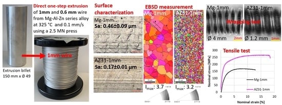
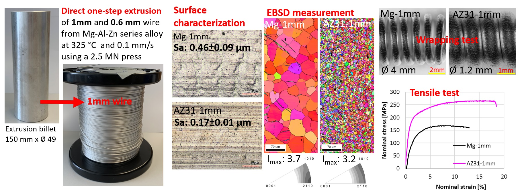
Based on these considerations, it was the aim of this paper to show the extrusion of magnesium alloy wires feasible directly in only one processing step with a wire thickness of 1 mm or smaller. The alloy specific correlation of the process to the developing microstructures and to excellent mechanical properties and surface conditions is revealed.
3. Results and Discussion
Processing:Table 2 shows the resulting extrusion parameters, the measured exit speeds of the wires during extrusion calculated from the gradient of time versus the ram position multiplied by the extrusion ratio, as well as the maximum extrusion force (peak force) which is related to the same extrusion parameter settings (T = 325 °C and
v = 0.1 mm/s) for all experiments.
Considering the speed and extrusion force, distinct differences can be observed for varying alloy composition and wire thickness. For the wires with 1 mm thickness, Mg has the lowest peak force of 1.36 MN, which increases to the capacity limit of the extrusion press at ca. 2.5 MN for AZ31. The peak force represents the beginning of the material flow and depends on the flow stress of the material in its respective condition and a force relevant component due to the friction between billet and container wall. Since all billets have the same initial length, the friction component is considered comparable. In all other cases, a corresponding decrease of the extrusion force was not found, leaving the extrusion experiments clearly at the press limit for AZ80 and AZ91, as well as for the 0.6 mm thick wire of AZ31. Correspondingly, the specified speed could not be reached because the force range was exhausted and the resulting extrusion speeds shown in
Table 2 are much lower than for Mg and AZ31 (1 mm). For the 1-mm wires, Mg shows the highest exit speed with 3.3 m/min followed by AZ31 with 2.8 m/min. AZ80 and AZ91 show significantly lower speeds with 0.9 and 1.6 m/min, respectively. The 0.6 mm AZ31 wire has by far the lowest exit speed with 0.4 m/min. The addition of the alloying elements and in particular aluminium obviously leads to a strengthening of the material between pure Mg and AZ31, which continues with the further increase of the aluminium content.
Thus, although extrusion was carried out close to the processing limit with these parameter settings (especially in the form of a low extrusion temperature), it is shown feasible. It is suggested that the processing temperature for AZ-series alloys can also be higher than the 325 °C of this study which would further improve the forming ability but not reach a processing limit, e.g., in the form of hot cracking.
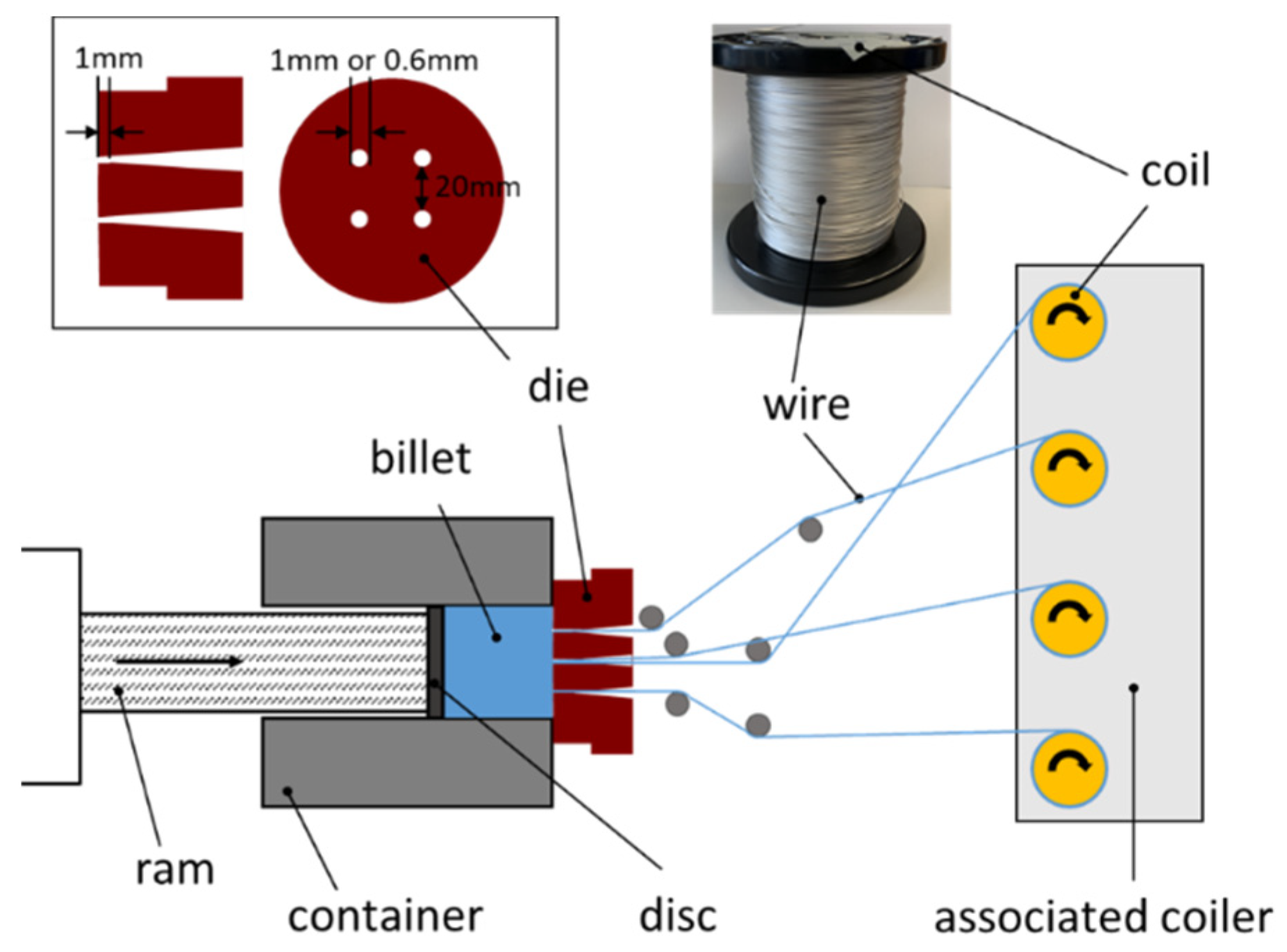
Microstructure and Texture Development: The grain structures and corresponding textures of the wires measured from longitudinal sections by EBSD are shown in
Figure 2. High angle grain boundaries (HAGB, with misorientation angles larger than 12°) are marked in black. The corresponding average grain sizes are listed in
Table 3.
All wires reveal a completely recrystallized microstructure with equiaxed grains. Vertical lines parallel to the extrusion direction are associated with particle stringers from precipitates. The Mg wire has by far the coarsest grain structure with an average grain size of 43 µm. The visible twins in the microstructure are remains from sample preparation, which is sometimes hard to avoid especially in large grains. The Al-containing wires with 1 mm thickness show considerably finer grained homogeneous microstructures. Although there is no visible difference between AZ31 (6.2 µm) and AZ80 (6.2 µm), the AZ91 wire is somewhat coarser grained at an average of 9.5 µm. It is noteworthy, that the same grain size of AZ31 and AZ80 with their different aluminium contents corresponds to a much lower resulting extrusion exit speed of the wires. On the contrary, the larger grain size of the AZ91 wire corresponds to a rather small variation in the alloy composition compared to AZ80, but a higher extrusion exit speed for AZ91 compared to AZ80. The thinner wire of AZ31 (0.6 mm) is also slightly finer grained at an average grain size of 5.3 µm, despite the significantly higher degree of deformation. However, the resulting extrusion speed is also the lowest in this study, which corresponds to this finest grained material. It is the hypothesis that the resulting lower extrusion speed limits deformation related heating, which leaves the recrystallized microstructure finer grained whereas the higher degree of deformation does not have a significant impact.
The very high degree of deformation imposed to the billet during extrusion results in considerable dynamic recrystallization during the forming process. The major impact on the kinetics of this dynamic recrystallization is due to temperature and deformation rate, often combined in the form of a temperature compensated strain rate, the Zener Hollomon parameter [
38,
39,
40,
41]. The impact of the imposed strain as a result of the extrusion ratio is indirectly included as the strain rate—seen as the extrusion exit speed—which results from a constant extrusion ram speed. It increases with increasing extrusion ratio. Furthermore, a higher strain rate during extrusion will result in higher deformation related heating, therefore increasing the relevant temperature for dynamic recrystallization [
42]. The above results on the grain size development do not allow a quantitative analysis regarding the kinetics of recrystallization but confirm a well-known grain refinement of alloying with aluminium in Mg. Furthermore, grain growth during recrystallization appears to increase with the profile exit speed and determines the microstructure development besides of alloying effects. Especially in the AZ80 wire, it is furthermore visible that a fraction of smaller grains developed in the vicinity of the stringer particles. This indicated a particle related growth restriction of grains during recrystallization. Earlier works have emphasized two important mechanisms in this regard: a particle related restriction of the grain boundary mobility due to the particles [
43] or a stimulation of recrystallization by particles which increases the nucleation rate of recrystallized grains [
44,
45]. As a result, of the fully recrystallized microstructures in cannot be distinguished which mechanisms dominated in this regard, however, a local effect on the developing texture cannot be revealed (not shown).
The inverse pole figures in the extrusion direction (ED) are also shown in
Figure 2 to represent the texture of the wires. As being typical for extruded round bars, a distinct preference for alignment of the basal planes parallel to the ED results. This is visible from the highest intensities in the pole figures along the arc between the <10
0>- and the <2
0> poles [
46]. Even further, in some cases the completely recrystallized microstructures correspond with high intensity at the <2
0> pole [
26]. This is especially pronounced for the Mg wire which has the most distinct texture with a maximum intensity of 3.7 m.r.d. With increasing content of Al from AZ31 to AZ91, the significance of the texture and the maximum intensity decrease, i.e., the orientation distribution has a more random character. AZ80 shows a maximum intensity of 2.5 m.r.d. and AZ91 of 1.9 m.r.d. The higher extrusion ratio of the thin 0.6 mm thick AZ31 wire corresponds to a more distinct development of intensity at the <2
0> pole compared to the wire with 1 mm thickness. This finding again corresponds to enhanced dynamic recrystallization despite the smaller grain size. In this case, a lower temperature increase and comparably retarded recrystallization during extrusion with the higher extrusion ratio is hypothetically balanced out by a further development of the recrystallized grain structure due to the higher imposed strain.
Especially in the case of the AZ80 wire, an inhomogeneity in the grain structure is visible due to lined-up sub-structures along the extrusion direction.
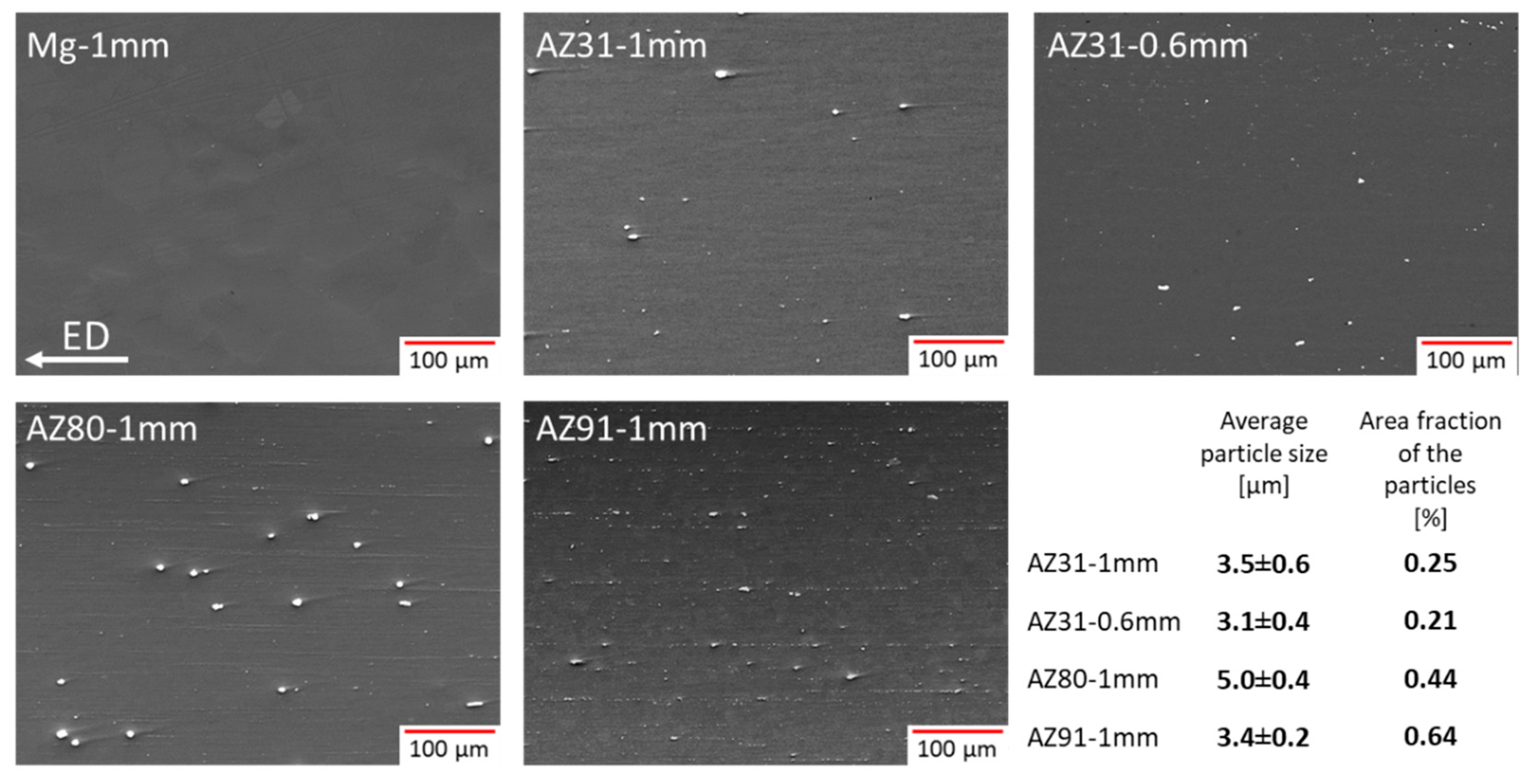
Figure 3 collects corresponding SEM images to reveal second phase particles in BSE-contrast (backscattered electrons). Additionally, the average particle size and the area fraction of the particles, measured on the represented image, are shown. Energy dispersive X-ray spectroscopy (EDX) reveals that all the particles measured consist of a combination of Al with Mn (not shown). No particles consistent with the stable Mg
17Al
12-phase could be identified throughout the alloys. Especially large particles are found in AZ80, not in AZ91. Note that the smaller average particle size corresponds to the obviously advanced grain growth in this alloy. On the other hand, the area fraction of particles increases continuously with the aluminium content. Furthermore, fine structures aligned in extrusion direction as particle stringers can be seen with increasing significance as the aluminium content increases.
While the precipitates are aligned as particle stringers or single particles with an ellipsoid form elongated to the extrusion direction, this is consistent with precipitates, which underwent deformation during extrusion and as a result aligned linearly in the extrusion direction. A potential deformation induced precipitation of these particles in not consistent with such an alignment but could result in a more random distribution of particles. Considering the particle size, AZ91 has the largest amount of precipitates, but AZ80 has by far the largest average particle size with 5.0 ± 0.4 µm. There is no significant difference in average particle size between AZ31 (1 mm and 0.6 mm wire) and AZ91.
The applied solid solution heat treatment at 400 °C prior to extrusion would preferentially lead to the dissolution of Mg
17Al
12 whereas Mn containing precipitates (Al
8Mn
5 or Al
4Mn have been reported) are stable up to the solidus and cannot be dissolved [
47]. However, the lower extrusion temperature at 325 °C also allows the formation of these Mn-containing precipitates. However, the fast cooling of the thin wires—air cooling occurs after extrusion—supports the suppression of the formation of newly formed precipitates during the processing, especially during cooling below a solvus temperature for the respective precipitates.
There are also no differences in the distribution of precipitation between the 1 mm and 0.6 mm AZ31 wire. Thus, in this case the deformation degree does not seem to have a strong influence on the distribution or stringer formation at these high degrees of deformation.
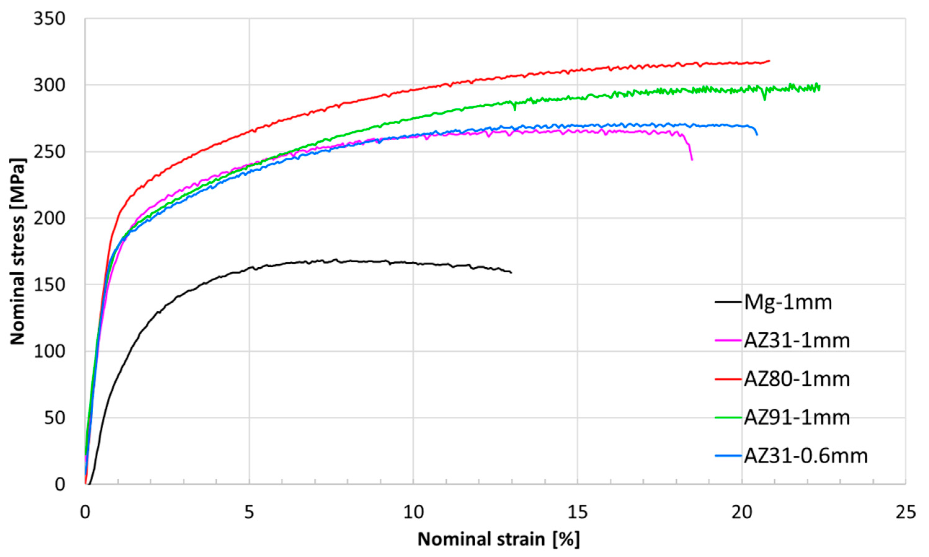
Mechanical Properties and Forming behavior: Stress-strain diagrams from tensile tests of the wires are shown in
Figure 4.
Table 3 also shows the mechanical properties and their standard deviation in addition to the grain sizes taken from the EBSD measurements (
Figure 2). Within the accuracy of the measurements, the results for AZ31 do not vary much. Higher Al content is consistent with an increase of both, stress and strain properties.
A continuous elasto-plastic yielding is followed by a typical strain hardening behavior with a continuous decrease of the slopes. The pure Mg wire is the only one that shows a following decrease of the stress levels after reaching a maximum stress level, obviously due to the occurrence of necking and the associated ductile behavior. Still, it reveals the lowest fracture strain with 11% and the lowest stress levels (yield stress (TYS) 90 MPa and maximum stress (UTS) 169 MPa) compared to the other wires of this study. For the Al-containing wires of AZ31, AZ80, and AZ91, the fracture strain increases with the Al content, from 16% for AZ31 to 21% for AZ91. None of these wires seems to exceed a uniform strain from where necking would become visible. However, while AZ31 seems to reach a limit of the stress level, strain hardening continues for AZ80 and especially for AZ91 until fracture.
The AZ80 wire shows the highest mechanical strength properties (TYS: 195 MPa; UTS 316 MPa) whereas AZ91 does not fully reach the same levels (TYS 180 MPa; UTS 302 MPa). Despite similar grain size, the strength properties of the AZ31 wires are even lower which is consistent with a lower strengthening effect due to the low Al content as an alloying element in solid solution [
48]. It is not assumed that the Al-Mn-containing particles contribute to material strengthening to a visible extent [
49]. Concurrent to their very similar microstructure properties, there are only very small variations in the mechanical behavior and the mechanical properties of the two AZ31 with different thickness, 1 mm and 0.6 mm, respectively. The variations of the comparably low average grain sizes will have a visible effect on the yield stress due to grain boundary strengthening (Hall-Petch relationship; see, e.g., Christian and Mahajan [
50]), which corresponds well with the lower stress levels of AZ91 compared to AZ80, despite the quite similar alloy composition. Furthermore, the weaker texture of the wires with higher Al-content corresponds to the higher ability to strain hardening. It is hypothesized that the weaker texture, i.e., less significant alignment of basal planes parallel to the extrusion direction, enables higher ability to accommodate plastic strain due to enhanced basal slip. However, at the onset of plastic deformation, lower stress will be required to activate this slip mode; therefore, the corresponding stress levels will also be lower. A corresponding effect of the texture in compression along the extrusion direction is not accessible due to the small dimensions of the wires. It is assumed that weaker textures will reduce the asymmetric yielding behavior due to reduced activation ability of deformation twinning [
24], which cannot be revealed experimentally in this work. It has been shown that this also has an impact towards increased fracture strains during compressive loading [
34].
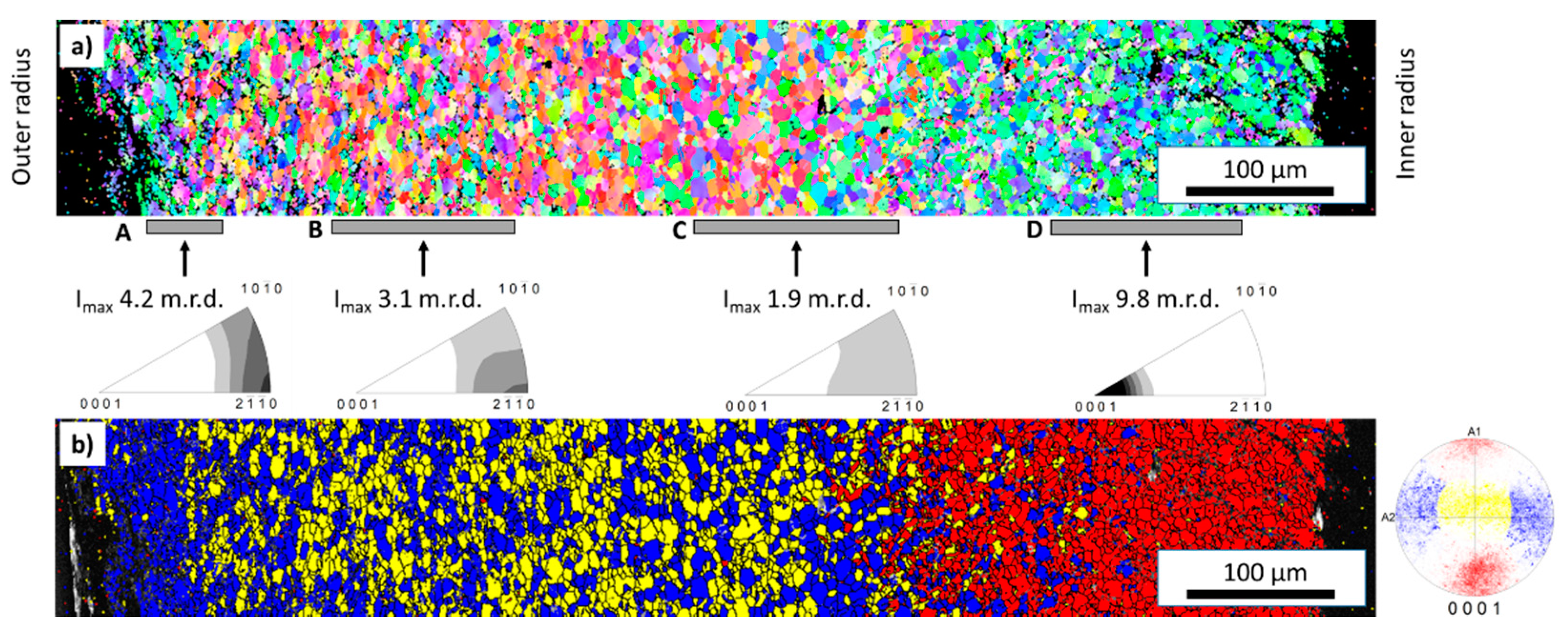
For an examination of the forming behavior of the wires with a combined effect of various strain, tensile and compressive strain, manual wrapping of the wires has been carried out with various inner core diameters. An exemplary cross-sectional grain map at mid-plane is shown in
Figure 5a, resulting from an EBSD measurement from the AZ31 wire (1 mm thickness, inner core 2 mm in diameter). There is a considerable change visible, which is supposed to represent the major features of the microstructure and texture development. The left-hand side of the image, the outer surface that underwent tensile strain, does not show much variation from the original texture only with the highest intensity at the <2
0> pole, see section A, thus revealing no strong texture change compared to the original texture in
Figure 2. This may be somewhat surprising if it is recalled that tensile strain typically leads to the formation of a prismatic plane alignment such that higher intensity is found for the <10
0> pole; see, e.g., Reference [
51,
52]. However, the strain level during wrapping may be too low to resolve such a change in the respective pole figure of the respective symmetric profile. Still, the grains in this range are in tendency elongated vertically which corresponds to the extrusion direction. Thus, the grain form was visibly influenced by the applied strain, which persists for a considerable 1/3 along the cross section. Concurrently towards the inner part of the wire, section B, basal planes appear to tilt further out of the extrusion direction, which is visible from the broader intensity distribution in the pole figure towards the <0001> pole. On the right-hand side, close to the centerline of the bent wire in section C, this development continues, leaving the texture very weak. This does not persist towards the inner surface of the wire on the right-hand side, section D. The pole figure reveals a component with a full tilt of basal planes and the corresponding c-axis parallel to ED. This rotation is consistent with this fraction of the microstructure undergoing twinning. Note, that almost no boundaries consistent with the lattice rotation of ca. 86° of tensile twins are found throughout the measurement (not shown), which indicates full twinning of the respective re-oriented grains. Grains also appear to be flattened horizontally, i.e., perpendicular to the wire extrusion direction.
In
Figure 5b, the same section is shown with highlighted fractions of orientations as selected from the corresponding (0001) pole figure. The blue and yellow fractions correspond to basal planes aligned parallel to the extrusion direction with c-axis vertical or horizontal to the measured mid-plane, respectively. Grains are oriented in correspondence to both fractions randomly on the outer surface side (left). The most inner part on the right-hand side is revealed in red which corresponds to a fraction of grains with c-axis parallel to ED. Assuming the associated grains as twinned grains it becomes visible that this affects only a small range of grains along the through-thickness measurement.
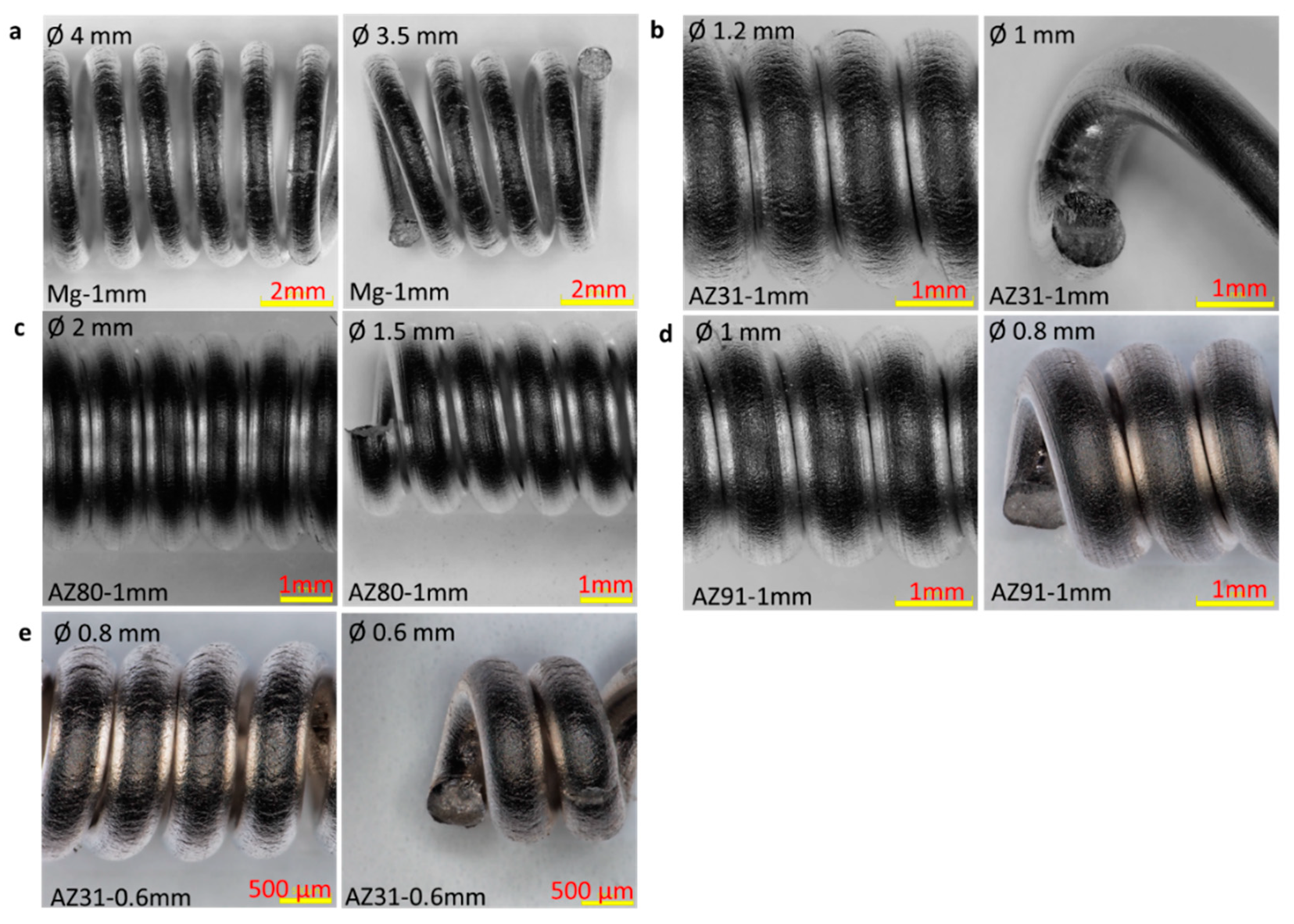
Results from wrapping tests in
Figure 6 were achieved in accordance to standard ISO 7802:2013 [
37]. For this purpose, the wires were manually wrapped around core sticks with defined diameters from 4 mm down to 0.6 mm at least 6 times. For each wire the figure shows one example of the minimum wrapping diameter before wire fracture (left picture), as well as one example of wrapping with wire fracture (right picture). The 1 mm thick Mg wire already showed failure when it was wrapped around a diameter of 3.5 mm and also showed cracks even at the 4 mm wrapping diameter, see
Figure 6a. The AZ80 wire achieves a wrap of 2 mm followed by the AZ31 wire of 1.2 mm diameter. Among the 1 mm thick wires, the AZ91 wire is the tightest to wrap (diameter 1 mm) and only fails at a wrapping diameter of 0.8 mm.
Considering the minimum diameter as a measure of the ductility for this multi-directional strain accommodation case, the results are quite comparable to those achieved from the tensile test. Only AZ80 shows a less ductile behavior compared to AZ31, which is contrary to the tensile test. If related to the difference in the activation of deformation mechanisms and especially the potential role of twinning, this finding seems counterintuitive. Then, the obviously special distribution of precipitates in the alloys may act differently if local shear and compressive strain components occur. If the material still has large amounts of precipitation, as is the case with AZ80 (see
Figure 3), stress peaks can arise, which can lead to a premature material failure. Beside this, it is confirmed that the higher Al-containing AZ91 wire shows excellent wrapping behavior compared to AZ31. The 0.6 mm thick AZ31 wire shows failure at a winding diameter of 0.6 mm and shows clear surface cracks even at 0.8 mm. Still, the behavior is consistent with the smaller wire thickness if compared to the 1 mm thick wire.
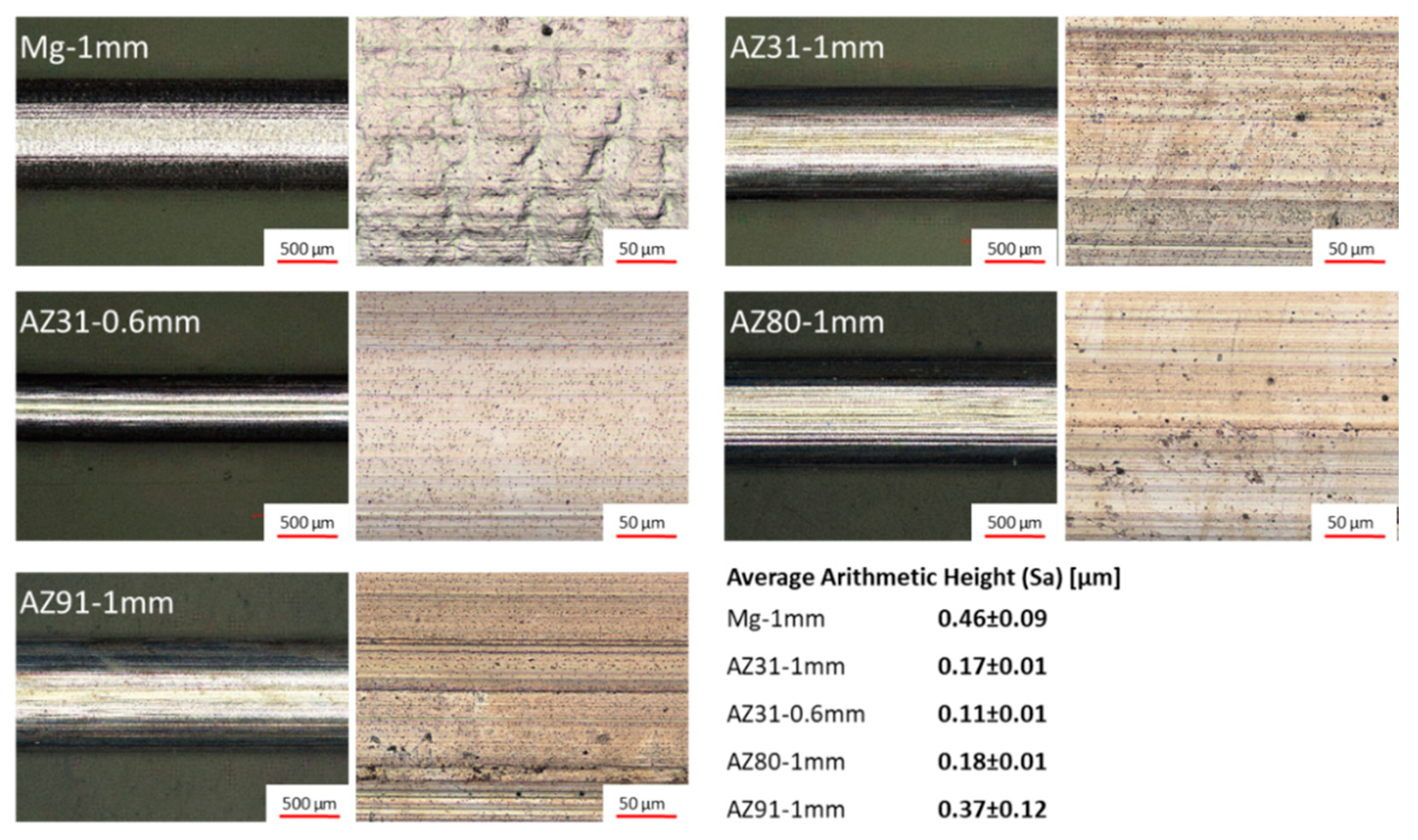
Surface characterization:Figure 7 shows the surface characteristics of the as-extruded wires in two magnifications, 50× and 500×. In addition, the surface roughness is shown as the average arithmetic height (Sa), as measured from the image with the higher magnification. There is an appreciable difference in the surface quality, associated with the alloy composition, as well as the resulting extrusion parameter variations (especially the speed). The pure Mg wire (1 mm) exhibits the highest roughness (0.46 µm) and shows an extremely uneven wavy surface compared to the Al-containing wires of AZ31, AZ80, and AZ91. The formation of the scratches in the extrusion direction becomes more pronounced with increasing Al content. This is also reflected in the roughness. Both AZ31 wires (0.6 and 1 mm thick) show the lowest roughness, despite the different extrusion speeds whereas the AZ91 wire shows the highest roughness (0.37 µm), except for pure Mg. The poor surface development of pure Mg has also been reported as a result of compressive strain in the case of forging [
53].
The number and depth of the grooves are detailed in
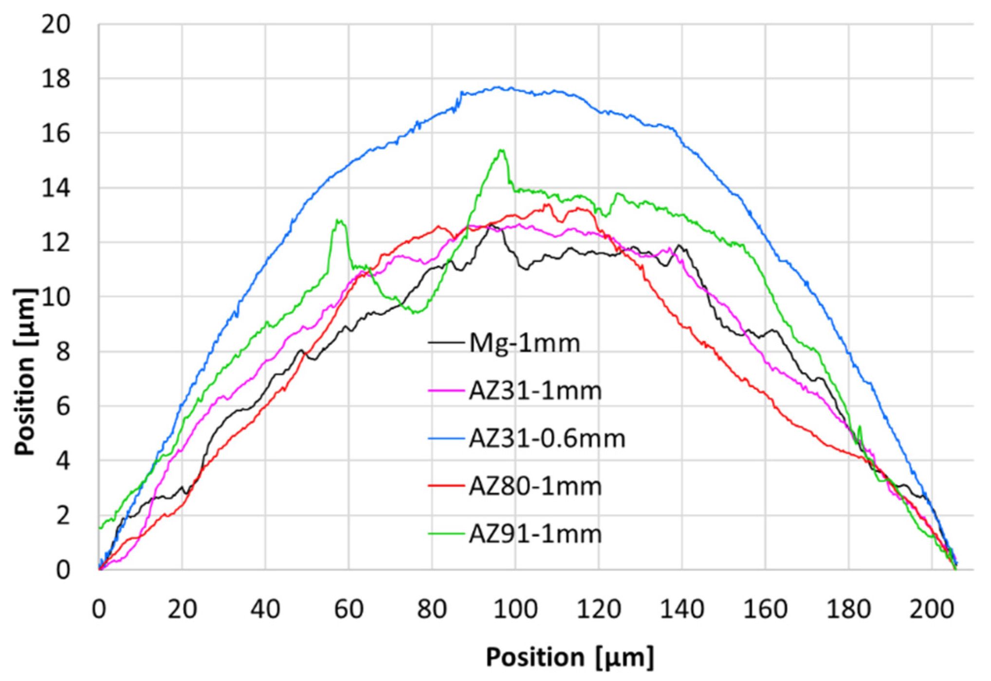
Figure 8 for the wires, which shows a vertical surface profile measurement taken from the images at 500× magnification. In this figure, the depth of the grooves can be compared best in the form of the fluctuations of the curves. Again, AZ31 is very smooth in both cases. The AZ80 wire has a pronounced concave depression on the right side which exemplarily points towards a general flow instability during the extrusion process. The AZ91 shows grooves of up to 5 µm depth. The same effect seems less pronounced in case of pure Mg with its different surface morphology. While the surface of pure Mg is determined by an inhomogeneous deformation behavior, which leads to surface bulging, this behavior is reduced with increasing Al content. On the contrary, the tendency to groove formation is increased with the Al content.
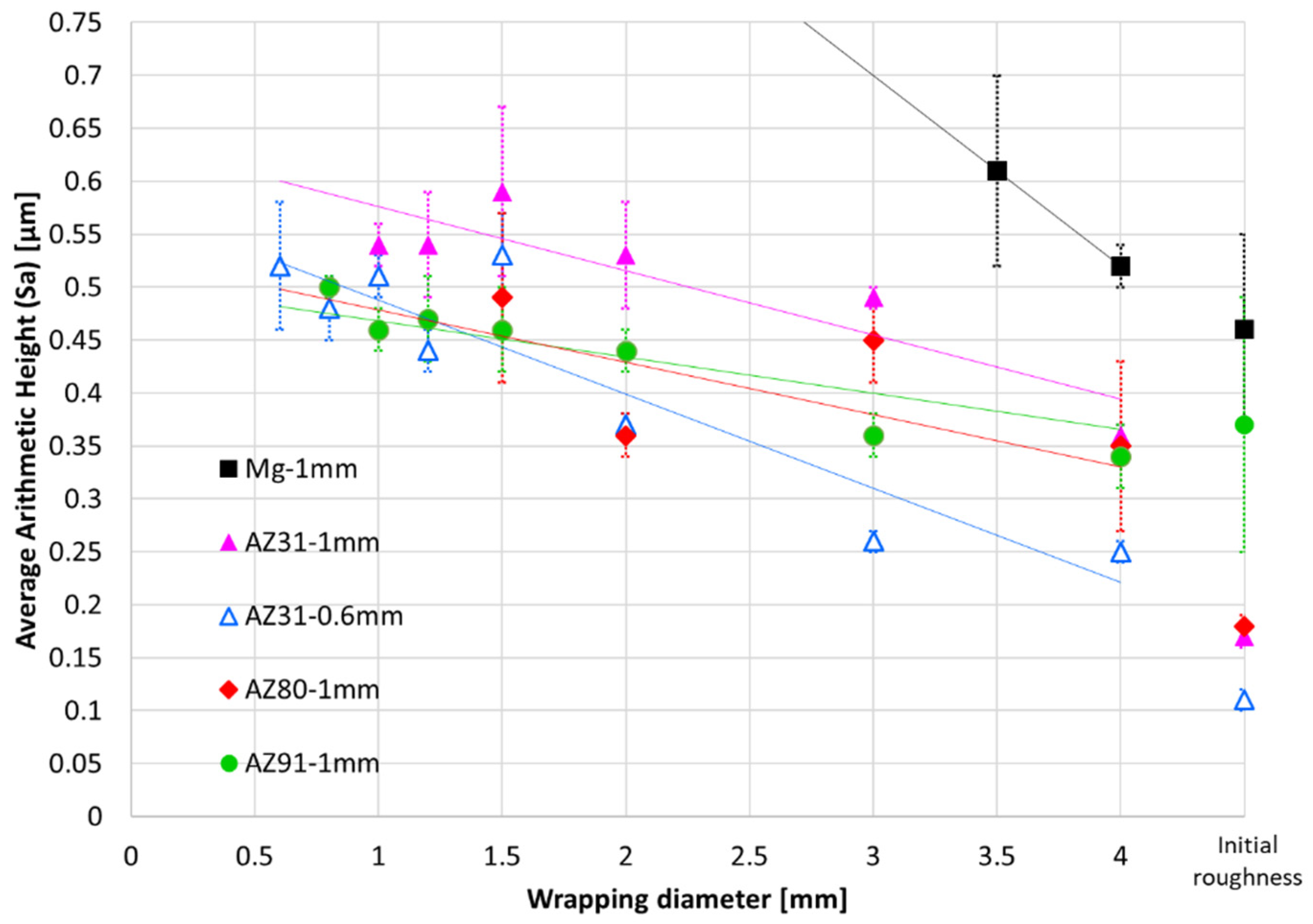
For the analysis of the influence of the wrapping test on the surface quality, roughness measurements were carried out on the wrapped wire surfaces. The results are presented in
Figure 9 versus the wrapping diameter. The increasing wrapping diameter along the horizontal axis is in accordance to a less challenging bending test. The surface roughness (Sa) in µm of the original wires (initial roughness) is shown as a benchmark. The surface roughness increases for all wires with smaller wrapping diameters. The Mg wire has the highest initial roughness (0.46 ± 0.09 µm), as well by far (0.61 ± 0.09 µm) after wrapping towards fracture at a diameter as high as 3.5 mm. For the AZ31 (1 mm) wire Sa increases from 0.17 ± 0.01 µm to 0.54 ± 0.02 µm, which is somewhat similar to the 0.6 mm AZ31 wire where Sa increases from 0.11 ± 0.01 µm to 0.52 ± 0.06 µm at material failure. Note that, at the respective wrapping diameters, the thicker wire experiences higher strain at the surface; therefore, the respective roughness is always higher compared to the thinner wire.
For the AZ80 wire, the roughness increase from 0.18 ± 0.01 µm to 0.49 ± 0.08 µm is somewhat unsteady and—if different in any way—possibly slightly lower than that of the AZ31 wire. Especially for the AZ91 wire, a remarkably low increase from the initial surface roughness of 0.37 ± 0.12 µm to 0.50 ± 0.01 µm is found. While the initial roughness is rather high (almost twice as high as that of the other Al-containing wires). Although the scattered results for AZ80 do not confirm this, the high Al content in AZ91 reveals a smoothening impact on the materials surface.


