Abstract
In recent years, the old-fashioned cylindrical cup shapes are still widely used, and there are many defects which could not be solved yet. In the present research, the classical earing defects, which are mainly caused by the material mechanical property of the anisotropic property of the material (R-value), are focused on. The multi draw radius (MDR) deep drawing die is applied and investigated to achieve nearly zero earing defects by encountering the R-value during the deep drawing process. Based on the experiments, in different directions in the sheet plane, the somewhat concurrent plastic deformation could be controlled, and the uniform elongated grain microstructure and uniform strain distributions on the cup wall could be achieved. Therefore, on the basis of these characteristics, the earing defects could be prevented, and the nearly zero earing defects could be achieved. However, to achieve the nearly zero earing defects, the suitable MDR die design relating to the R-value should be strictly considered. In the present research, to apply the MDR die for the medium carbon steel sheet grade SPCC cylindrical drawn cup, the following was recommended: the large draw radius positioned at 45° to the rolling direction and the small draw radius positioned along the plane and at 90° to the rolling direction. Therefore, in the present research, it was originally revealed that the nearly zero earing defects could be successfully performed on the process by using the MDR die application.
1. Introduction
Sheet-metal products are increasingly fabricated to serve in various manufacturing industries especially the aerospace industry, electronics industry, and automobile industry. The complex shapes with high precision are also increasingly required in recent years. These products are commonly fabricated by sheet-metal forming processes such as bending, stamping, and deep drawing processes. Therefore, based on the experiments and finite element method (FEM) techniques, many studies have been performed and also reported by researchers and engineers to develop these sheet-metal forming processes and meet the mentioned requirements. Several researchers have focused on improving the quality of sheet-metal products as well as manufacturing the complex shapes with high precision through that associated with the experiments and FEM techniques [1,2,3,4]. In contrast, in terms of old-fashioned cylindrical cup shapes, the cylindrical cups are still widely used in various sheet-metal manufacturing industries. In general, almost all of them are conventionally fashioned by deep drawing process. On the basis of experimental and FEM works, the developments on this process have been continuously reported in many past studies [5,6,7,8,9]. For examples, Mahdavian and Tui Mei Yen [5] determined the effect of different punches’ head profiles on the deep drawing of 5005H34 aluminium circular blanks to manufacture a cup-shape product. Nei et al. [6] investigated the deep drawing at various temperatures and studied the microstructure evolutions of three typical regions including bottom, corner, and wall taken from the drawn cylindrical part with the largest limiting drawing ratio (LDR). Liu et al. [7] showed the increase in the formability and quality of the pure aluminium spherical bottom cylindrical parts (SBCP) by using magnetic medium-assisted sheet metal drawing process. Bassoil et al. [8] studied the effects of a draw bead working on an Al6014-T4 strip according to assigned industrial conditions by the handy draw bead simulator (DBS). Sezek et al. [9] educated the effects of the die radius on blankholder forces and drawing ratio. The results also showed that the major parameters affected cup wall thickness were blankholder force, die radius, and lubricant use. However, in terms of earing defects as shown in Figure 1, there are few studies that have carried out the investigation and prevention these defects [10,11,12,13,14,15]. Marton et al. [10] investigated the prediction of the earing defect on 0.3 and 3.0 mm thick cold rolled 1050 type aluminium sheets subjected to annealing heat treatments for different time intervals to promote the recrystallization processes and obtain different earing behaviors. It was shown that the proposed method was able to predict the type and magnitude of earing with satisfactory results for both 0.3 and 3.0 mm sheet thicknesses. Kishor and Kumar [11] studied the earing problem in deep drawing of flat bottom cylindrical cups using the FEM (LSDYNA). The optimization of the initial blank shape was proposed to meet the smallest earing defects. Walde and Riedel [12] investigated the earing defects on the magnesium alloy AZ31 that the crystallographic texture and plastic anisotropy were usually pronounced during the rolling process. Based on the FEM in conjunction with a viscoplastic self-consistent texture model, the results showed that not only on the initial texture of sheet metal but also the evolution of texture during drawing process caused the earing defects. Izadpanah et al. [13] studied the deformation behaviors of sheet metals using advanced anisotropic yield criteria by FEM simulation. The results revealed that the earing profile and thickness distribution obtained from experiments well corresponded with FEM simulations. Cazacu et al. [14] proposed the anisotropy plasticity CPB06 theory, and Singh et al. [15] applied and implemented it in an FE model to predict the nonuniform material flow characteristics, earing defects, and thickness distributions successfully. Some studies were performed to prevent earing defects by making the material property into isotropic material. Olaf Engler et al. [16] studied the microstructure evolutions resulting in earing profiles on the Al alloy (AA8011A) during the down-stream process. The results showed that the earing defects could be controlled. Tang et al. [17] studied the microstructure and texture, tensile mechanical properties in terms of strength and elongation, and the anisotropy of conventional unidirectional rolling (UR) and cross rolling (CR) sheets at room temperature. The results showed that the CR sheet produced a deeper drawn cup than that of the UR sheet due to its lower normal anisotropy value and layer elongation compared with those of the UR sheet. However, these techniques cause the increases in additional rolling operations resulting in the increases in production cost and time consuming. Next, by using the FEM, the studies have been focused on the applications of models, while the proposal of new anisotropy models is not covered. In addition, Phanitwong and Thipprakmas [18], by using multidraw radius (MDR), showed the interesting results of material flow characteristics during the deep drawing process in which the nonaxisymmetric material flow characteristic due to the anisotropy property of the material could be encountered by using the MDR die, and the axisymmetric material flow characteristic could be formed. Therefore, in the present research, the new idea of MDR application for the earing prevention during the deep drawing process is proposed. Specifically, the different draw radius positioned in different directions in the sheet plane was designed to encounter the material mechanical property of the anisotropy property of the material, and then the earing could be prevented. The MDR die seemed to be difficult to design and fabricate due to the complicated three-dimensional shape of draw radius (die shoulder radius or hole edge corner radius). However, based on the computer-aided design (CAD) and computer-aided manufacturing (CAM) technologies nowadays, this MDR die could be designed and fabricated in general. In addition, by comparing with other techniques applied for the deep drawing process such as draw bead application, this MDR die application shows the less process parameters to be concerned. Therefore, as the benefits of this application, it is easier to set the process parameters, and it can be performed on the deep drawing operation with no any additional operations. This results in the decreases in the production cost and time consumption. However, the conceptual design of MDR deep drawing die is strictly designed related to the R-value. As the results, they originally revealed that the MDR deep drawing die could be useful to reduce earing defects as well as to meet the nearly zero earing defects with no additional operations.
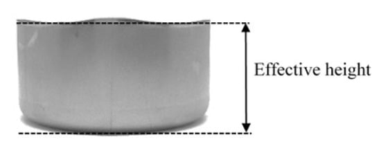
Figure 1.
Earing defects and effective height of deep drawn parts.
2. Materials and Method
In the present research, the medium carbon steel sheet grade SPCC (JIS) with the thickness of 0.975 mm was used as a workpiece material. The chemical compositions were listed in Table 1. The mechanical properties were also examined by the tensile testing technique, and they were listed in Table 2. As a major material property that affected the earing defects, the R-value along the plane, at 45 and 90° to the rolling direction were examined, and they were 2.1, 1.9, and 2.6, respectively. Table 2 also shows the other material properties of Young’s modulus, Poisson’s ratio, and ultimate tensile strength. The microstructures along the plane, at 45 and 90° to the rolling direction were examined as well. The sheet materials were also sectioned and further processed by subsequent mounting, polishing, and etching with 2% nital etchant. Optical microscopy was used to observe and capture microstructure images for microscopic examinations. The images of examined microscopic along the plane, at 45 and 90° to the rolling direction are, respectively, shown in Figure 2a–c. In addition, the grain sizes were also examined on both horizontal and vertical (thickness) directions as they were also reported in Figure 2. The cylindrical cup of 60.0 mm in diameter, 26.2 mm in height, and 5.0 mm in cup bottom radius, as shown in Figure 3, was used as a model of cylindrical deep drawn cup. To fabricate this cup, the initial blank size of 100.0 mm was calculated based on the deep drawing theory [19]. The initial blank was prepared by using a wire electrical discharge machine (Wire-EDM, Sodick Model AQ325L, Yokohama, Kanagawa, Japan). Figure 4a shows the punch and die designed based on the deep drawing theory [19]. As listed in Table 3, the punch diameter of 57.8 mm and die diameter of 60.0 mm were set. The die radius of 5.0 mm was designed. The deep drawing clearance of 1.1 mm was set. Figure 4b shows the press machine, which includes a universal sheet metal testing machine (JT TOHSI INC., Model SAS-350D, Minato-ku, Tokyo, Japan). After the deep drawing process, the obtained cylindrical cups were sectioned by a wire-EDM machine for material thickness examinations. The material thickness was measured using a digital micrometer (Insize, serie IS13108, Loganville, GA, USA). The cup height was measured using a vernier height gauge (Mitutoyo, Model CD-6” ASX, Kawasaki, Kanagawa, Japan), and the earing defects were calculated. Five samples from each deep drawing condition were used to inspect the obtained cylindrical cups. The amount of material thickness and earing defects were calculated based on these obtained cylindrical cups, and the average material thickness and earing defect values were reported.

Table 1.
Chemical compositions of SPCC steel (JIS).
Table 2.
Mechanical properties of SPCC steel (JIS).
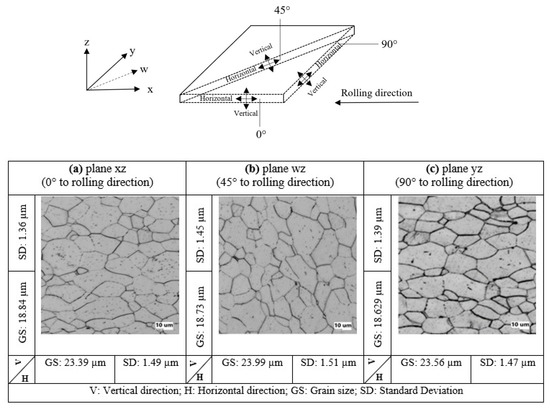
Figure 2.
Microstructure examinations of SPCC steel (JIS): (a) plane xz (0° to rolling direction); (b) plane wz (at 45° to rolling direction); (c) plane yz (at 90° to rolling direction).
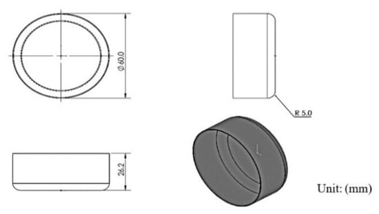
Figure 3.
Model of cylindrical deep drawn part.
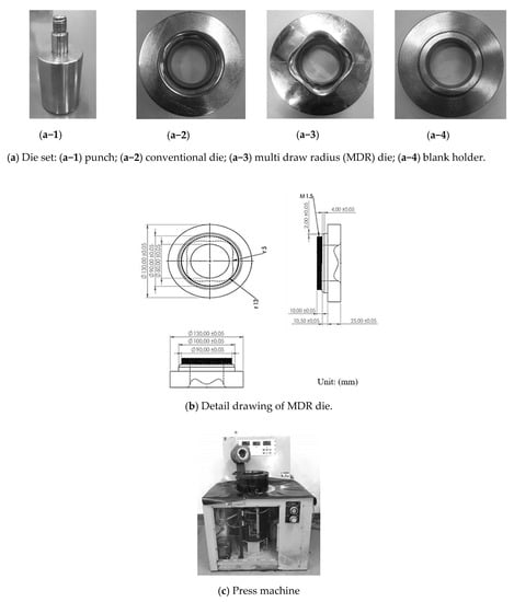
Figure 4.
Die set for experiment and press machine: (a) die set; (b) detail drawing of MDR die; (c) press machine.
Table 3.
Experimental conditions.
3. Results and Discussion
3.1. Analysis of the Microstructure Evolutions, Strain Distributions, and Thickness Distributions on Deep Drawn Parts Using Conventional Dies
As per the deep drawing theory [19], the cylindrical cup is initially formed after the blank is drawn over the draw radius. This characteristic resulted in the microstructure evolutions and generated strain distributions on the cup. Specifically, the crystal grain deformed adjusting to macroscopic deformation, and so the deformation of crystal grain would naturally correspond to macroscopic strain. On the basis of the fundamentals of the deep drawing mechanism, the material at the cup bottom zone was subjected to equi-biaxial tension and the stretching flange deformation was generated based on the equi-biaxial elongation. This deformation characteristic commonly results in the material thinning. The stretching flange characteristic also commonly formed at the cup bottom radius zone. The bending characteristic was formed at this zone, in addition. Therefore, in general, the material thinning was greatest, and the possibility of breakage was also the highest at the cup bottom radius zone. Next, to form a cup wall, the material at flange portion moves in the direction to the center of die, and then this material must shrink in circular direction. As these characteristics, the tension and compression stresses are commonly generated in radial and circular directions, respectively. Therefore, the material elongates and shrinks in radial and circular directions, respectively. Based on these characteristics, after the cup wall completely formed, the earing defects were simultaneously generated. Therefore, relating to the R-value, the analysis of the microstructure evolutions and strain distributions on the cup wall zone was focused on in the present research to clarify the earing defects as well as to use as fundamental information for a new die design to prevent earing defects. In comparison to the initial blank sheet, the microstructure evolutions along the plane at 45 and 90° to the rolling direction at the middle and near edge of the cup walls in the case of a draw radius of 5.0 and 13.0 mm are shown in Figure 5. The examined elongated grains in the horizontal and vertical directions were reported as well. Based on these examined grain sizes, the logarithmic strain in each direction was calculated based on Equation (1). Therefore, by the same token, the logarithmic strains in radial and thickness directions could be calculated as well. Next, by using the volume constancy law, the logarithmic strain in the circular direction could be calculated following Equation (2), and they were reported in the Figure 6.
when l0 is the initial grain size and l is the deformed grain size.
when εθ is the logarithmic strain in the circular direction, εr is the logarithmic strain in the radial direction, and εt is the logarithmic strain in the thickness direction.
Logarithmic strain = ln (l/l0)
εθ = −(εr + εt)
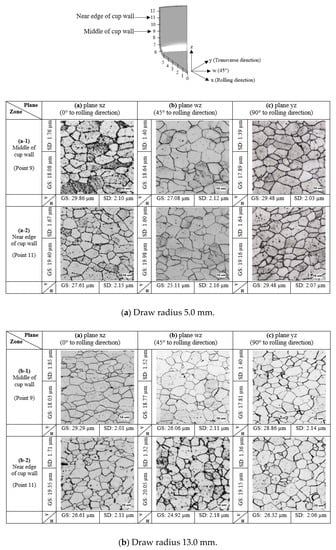
Figure 5.
Comparison of microstructure evolutions on deep drawn parts with respect to draw radii: (a) draw radius 5.0 mm; (b) draw radius 13.0 mm.
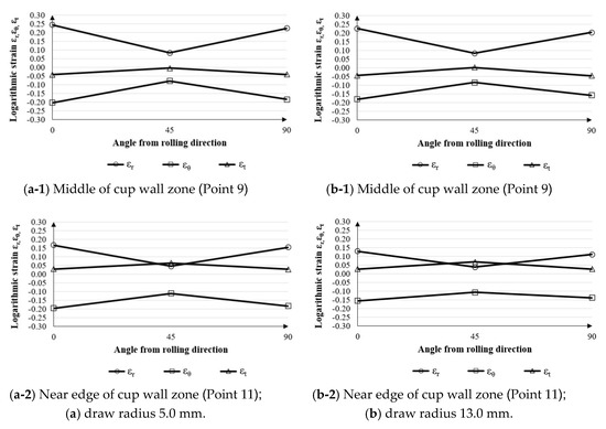
Figure 6.
Strain distributions on cup wall zone with respect to draw radii: (a) draw radius 5.0 mm; (b) draw radius 13.0 mm.
The same manner of strain distribution analysis in the cases of a draw radius of 5.0 and 13.0 mm could be observed. In terms of thickness strain distribution, it was negative in all directions in the sheet plane. The large negative thickness strain was generated in the direction along the plane and at 90° to the rolling direction, and the small negative one was generated in the direction at 45° to the rolling direction. In comparison to the middle cup wall zone, at the near edge of the cup wall, the positive thickness strain was generated instead of the negative one. Again, the large thickness strain was still generated in the direction at 45° to the rolling direction. Therefore, the material thinning was formed at the middle of cup wall, whereas the material thickening was formed at the near edge of the cup wall. To validate these results, the thickness examinations were carried out, and the thickness distributions are shown in Figure 7. There was a small change of material thickness on the cup bottom zone due to the stretching flange deformation characteristic. However, the maximum material thinning was generated on the cup bottom radius because the bending was added to the stretching flange deformation characteristics, and then the large plastic deformation was generated in that area. It was also observed that the changes in material thickness with respect to draw radii were somewhat at the same level. The effects of the rolling direction on the material thickness of the cup bottom zone and cup bottom radius zone were very small. With the cup wall zone, the results showed that the material thinning was decreased along the cup wall height. The effects of the rolling direction on material thickness were clearly illustrated, especially on the cup wall zone. These thickness distribution results agreed well with the thickness strain distribution results calculated on the basis of the deformed grain size. These results also corresponded well with the deep drawing theory and literature [18,19]. Next, in terms of radial strain and circular strain distributions, the radial strain was positive, but the circular strain was negative. The large radial strain was generated in the direction along the plane and at 90° to the rolling direction, and the small one was generated in the direction at 45° to the rolling direction. Again, the large circular strain was generated in the direction along the plane and at 90° to the rolling direction, and the small one was generated in the direction at 45° to the rolling direction. These results could be explained that, owing to the R-value as listed in Table 2, the plastic deformation would occur earlier in the direction along the plane and at 90° to the rolling direction due to the large R-value. Therefore, the material would flow into these directions from other portions, i.e., the portion at 45° to the rolling direction. Therefore, the nonconcurrent plastic deformation was generated and then caused the restriction of material flown into the die. In addition, the highly excessive elongating material flowed outward in the direction to edge of the blank sheet. Therefore, the earing defects were formed by the peak of the earing profile that was along the plane and at 90° to the rolling direction, whereas the bottom of the earing profile was at 45° to the rolling direction. Figure 8a,b show the earing defects in the case of a draw radius of 5.0 and 13.0 mm, respectively. The obtained earing defects were approximately of 1.7 mm in both cases of the draw radius of 5.0 and 13.0 mm. It was also observed that the peak of the earing profile formed along the plane and at 90° to the rolling direction, whereas the bottom of the earing profile formed at 45° to the rolling direction. They agreed well with radial and circular strain distributions calculated on the basis of the deformed grain size. These results also corresponded well with the deep drawing theory and literature [18,19]. As a result, based on the microstructure evolutions and strain distributions, the occurrence of earing defects could be clearly clarified. These data are valuable information for supporting MDR die design and development to achieve the nearly zero earing defects.
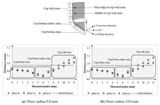
Figure 7.
Thickness distributions on deep drawn parts with respect to draw radii: (a) draw radius 5.0 mm; (b) draw radius 13.0 mm.
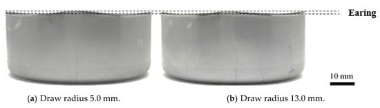
Figure 8.
Earing defects with respect to draw radius obtained from the conventional die application: (a) draw radius 5.0 mm; (b) draw radius 13.0 mm.
3.2. Conceptual Design of Multi Draw Radius (MDR) Deep Drawing Die
As per the author past research [18], the multi draw radius (MDR) deep drawing die is mainly proposed to increase the limiting drawing ratio of cylindrical deep drawn parts (LDR) by reducing the nonaxisymmetric material flow during deep drawing process. In the present research, this MDR die was proposed and applied to prevent the earing defects. Figure 9 shows the conceptual design of the MDR die. By using the conventional die, as shown in Figure 9a, the nonconcurrent plastic deformation characteristic was formed during the deep drawing process because of the effects of the R-value. As aforementioned, the plastic deformation would occur more early in the direction along the plane and at 90° to the rolling direction due to the large R-value. This resulted in the restriction of material flown into the die due to the highly excessive elongating material flow into these directions from other portions. Then, the nonaxisymmetric material flow characteristic on the flange portion during the deep drawing process was generated [18]. These plastic deformation and material flow characteristics caused the material in the direction along the plane and at 90° to the rolling direction were easier to stretch compared to that in direction at 45° to the rolling direction, and then, the earing defects were formed. To encounter these characteristics and prevent earing defects, the later plastic deformation generated in the direction at 45° to the rolling direction should be driven to generate earlier as it generated in the direction along the plane and at 90° to the rolling direction. Therefore, the plastic deformation in different directions in the sheet plane during the deep drawing process could be concurrently generated. As per the past research [18], by using the MDR die, the axisymmetric material flow characteristic could be achieved. Therefore, the MDR die might be able to solve the above-mentioned plastic deformation characteristic and earing defects. As suggested in the past research, the larger draw radius was positioned at 45° to the rolling direction and the smaller draw radius positioned along the plane and at 90° to the rolling direction. This resulted in the plastic deformation generating in the direction at 45° to the rolling direction, which could be made to occur earlier, and then the concurrent plastic deformation characteristic could be controlled, as shown in Figure 9b. The uniform material stretching in each direction in the sheet plane could be generated, and the uniform strain distribution in each direction in the sheet plane could be obtained. Concerning these plastic deformation mechanisms, by using the MDR die, the achievement of nearly zero earing defects by the process encountering the material mechanical property of the anisotropy property of the material could be met. However, the draw radius in each direction in the sheet plane should be positioned as follows: the larger draw radius positioned at 45° to the rolling direction and the smaller draw radius positioned along the plane and at 90° to the rolling direction. In the present research, the different MDR dies were investigated to achieve nearly zero earing defects, and the results are shown in Figure 10. Specifically, the small draw radius of 5.0 mm, as recommended for conventional deep drawing die, was positioned along the plane and at 90° to the rolling direction. The large draw radius of 6.0–14.0 mm was positioned at 45° to the rolling direction. The results showed the decreases, and again, the increases in the earing defects as the large draw radius increased. The smallest earing defects approximately of 0.1 mm could be generated with the large draw radius of 13.0 mm applied.
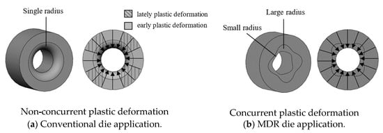
Figure 9.
Illustration of plastic deformation characteristics with respect to die types: (a) conventional die application; (b) MDR die application.
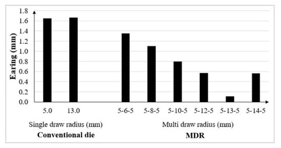
Figure 10.
Comparison of earing defects between conventional and MDR die applications.
3.3. Application of Multidraw Radius (MDR) Deep Drawing Die
As aforementioned, the small draw radius of 5.0 mm, as recommended for conventional deep drawing die, was positioned along the plane and at 90° to the rolling direction, and the large draw radius of 13.0 mm positioned at 45° to the rolling direction was designed to achieve nearly zero earing defects. As this MDR die was applied, the nearly uniform elongated grain microstructure evolutions in each direction in the sheet plane could be achieved and the earing defects could be prevented. The examined microstructure evolutions are shown in Figure 11b, and the examined elongated grains in horizontal and vertical directions were reported as well. By comparing the conventional die use, these results revealed that by using the MDR die, the microstructure evolutions in each direction in the sheet plane during the deep drawing process, especially on the cup wall zone, could be encountered by the multi draw radius, and the nearly uniform elongated grain in each direction in the sheet plane on each cup wall height, i.e., the middle and near edge of cup walls, could be achieved. In terms of strain distribution, as shown in Figure 12b, by comparing with the conventional die use, the changes in radial, circular, and thickness strains in the direction at 45° to the rolling direction were clearly identified. Specifically, the radial strain was increased in the positive direction, but the circular and thickness strains were increased in the negative direction. In addition, the strain distributions also showed the interesting results that the nearly uniform strain distribution in each direction in the sheet plane on each cup wall height, i.e., the middle and near edge of cup walls, could be achieved. In terms of thickness distribution, as shown in Figure 13b, the thickness distributions showed the good agreement with the strain distribution results. As the thickness strain in the direction at 45° to the rolling direction increased in the negative direction, the thickness distribution showed the decreases in material thickness compared to that in the case of conventional die use. Moreover, the nearly uniform thickness distribution in each direction in the sheet plane on each cup wall height could be achieved. Based on these microstructure evolutions, strain distributions, and thickness distributions, in terms of earing defects, as shown in Figure 14, the results revealed that the earing defects could be reduced, and the nearly zero earing defects could be achieved. The results showed that, by using the MDR die, the earing defects of approximately 0.1 mm were formed. To more clearly clarify the MDR die use, the MDR die of large die radius of 12.0 mm was also designed and investigated. Again, the results of microstructure evolutions, strain distributions, and thickness distributions are shown in Figure 11b, Figure 12b, and Figure 13b, respectively. The same characteristics of those MDRs with the large die radius of 13.0 mm use could be observed. However, it could be noted that the increases in radial, circular, and thickness strains were smaller than those in the case of MDR with a die radius of 13 mm use. Therefore, the earing defects were larger. These results confirmed that, by using the MDR die, the nearly zero earing defects could be achieved. However, the suitable MDR die design relating to the R-value of material should be strictly considered.
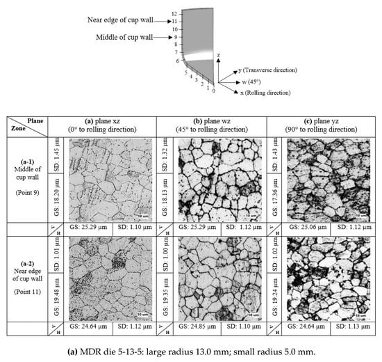
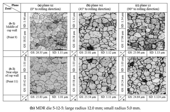
Figure 11.
Comparison of microstructure evolutions on deep drawn parts with respect to MDR dies: (a) MDR die 5-13-5; (b) MDR die 5-12-5.
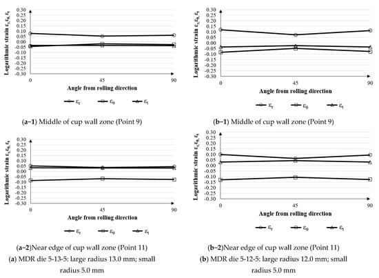
Figure 12.
Comparison of strain distributions on cup wall zone with respect to MDR dies: (a) MDR die 5-13-5; (b) MDR die 5-12-5.
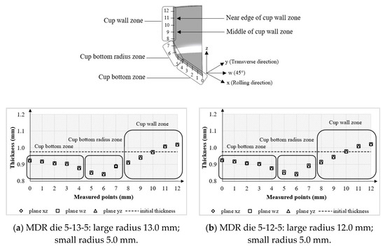
Figure 13.
Illustration of thickness distributions on deep drawn parts with respect to MDR dies: (a) MDR die 5-13-5; (b) MDR die 5-12-5.
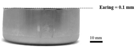
Figure 14.
Illustration of earing defects on deep drawn part by using the MDR die.
4. Conclusions
In the present research, the earing defects as the major problem in the deep drawing process, especially for cylindrical drawn parts, were focused on. The MDR die application was proposed for reducing the earing defects as well as for achieving the nearly zero earing defects in the cylindrical deep drawing process. First, the effects of the draw radius on microstructure evolutions, strain distributions, thickness distributions, and earing defects were investigated. The results confirmed that, based on the material mechanical property of the R-value, the draw radius significantly caused the microstructure evolutions in different directions in the sheet plane. In addition, the changes in these microstructure evolutions significantly affected the strain and thickness distributions in different directions in the sheet plane, and then, the earing defects were formed. However, the changes in the draw radius rarely affected these microstructure evolutions, strain and thickness distributions, and earing defects. Next, the MDR die was applied and investigated to prevent earing defects. It was designed based on the principle of that, during the deep drawing process, the multi draw radius could encounter the effects of the R-value on microstructure evolutions and strain distributions in each direction in the sheet plane, especially on the cup wall zone. The plastic deformation generated in each direction in the sheet plane should be concurrently performed, and the axisymmetric material flow characteristic could be achieved. Therefore, the nearly uniform elongated grains in each direction in the sheet plane on each cup wall height could be achieved, and the nearly uniform strain and thickness distributions, especially on cup wall zone in each direction in the sheet plane, could be formed. Based on these microstructure evolutions, strain distributions and thickness distributions, the earing defects could be reduced, and the nearly zero earing defects could be achieved by using the MDR die. However, to achieve the nearly zero earing defects, the suitable MDR die design relating to the R-value should be strictly considered. In the present research, it was suggested that the larger draw radius should be positioned at 45° to the rolling direction and the smaller draw radius positioned along the plane and at 90° to the rolling direction.
Author Contributions
Conceptualization, R.J. and S.T.; data curation, R.J. and S.T.; funding acquisition, R.J. and S.T.; investigation, R.J.; methodology, R.J. and S.T.; project administration, S.T.; supervision, S.T.; writing—original draft, R.J.; writing—review and editing, S.T. All authors have read and agreed to the published version of the manuscript.
Funding
This research was funded by the “Petchra Pra Jom Klao Master’s Degree Research Scholarship” from King Mongkut’s University of Technology Thonburi. The APC was also funded by King Mongkut’s University of Technology Thonburi.
Acknowledgments
The authors would like to express their gratitude to Wiriyakorn Phanitwong, Department of Industrial Engineering, Rajamangala University of Technology Rattanakosin, and Arkarapon Sontamino, Department of Mechanical Engineering Technology, College of Industrial Technology, King Mongkut’s University of Technology North Bangkok for their advice on experiments in this present research.
Conflicts of Interest
The authors declare no conflict of interest.
References
- Cao, Q.; Du, L.; Li, Z.; Lai, Z.; Li, Z.; Chen, M.; Li, X.; Xu, S.; Chen, Q.; Han, X.; et al. Investigation of the Lorentz-force-driven sheet metal stamping process for cylindrical cup forming. J. Mater. Process. Technol. 2019, 271, 532–541. [Google Scholar] [CrossRef]
- Hashemi, A.; Gollo, M.H.; Seyedkashi, S.M.H. Study of Al/St laminated sheet and constituent layers in radial pressure-assisted hydrodynamic deep drawing. Mater. Manuf. Process. 2017, 32, 54–61. [Google Scholar] [CrossRef]
- Thipprakmas, S. Finite element analysis of sided coined-bead technique in precision V-bending process. Int. J. Adv. Manuf. Technol. 2013, 65, 679–688. [Google Scholar] [CrossRef]
- Phanitwong, W.; Thipprakmas, S. Centered coined-bead technique for precise U-bent part fabrication. Int. J. Adv. Manuf. Technol. 2016, 84, 2139–2150. [Google Scholar] [CrossRef]
- Mahdavian, S.; Fion, T.M.Y. Effect of Punch Geometry in the Deep Drawing Process of Aluminium. Mater. Manuf. Process. 2007, 22, 898–902. [Google Scholar] [CrossRef]
- Nie, H.; Chi, C.; Chen, H.; Li, X.; Liang, W. Microstructure evolution of Al/Mg/Al laminates in deep drawing process. J. Mater. Res. Technol. 2019, 8, 5325–5335. [Google Scholar] [CrossRef]
- Liu, Y.; Li, F.; Li, C.; Xu, J. Enhancing formability of spherical bottom cylindrical parts with magnetic medium on deep drawing process. Int. J. Adv. Manuf. Technol. 2019, 103, 1669–1679. [Google Scholar] [CrossRef]
- Bassoli, E.; Sola, A.; Denti, L.; Gatto, A. Experimental approach to measure the restraining force in deep drawing by means of a versatile draw bead simulator. Mater. Manuf. Process. 2019, 34, 1286–1295. [Google Scholar] [CrossRef]
- Sezek, S.; Savas, V.; Aksakal, B. Effect of Die Radius on Blank Holder Force and Drawing Ratio: A Model and Experimental Investigation. Mater. Manuf. Process. 2010, 25, 557–564. [Google Scholar] [CrossRef]
- Benke, M.; Hlavacs, A.; Piller, I.; Mertinger, V. Prediction of earing of aluminium sheets from {h00} pole figures. Eur. J. Mech. A Solids 2020, 81, 103950. [Google Scholar] [CrossRef]
- Kishor, N.; Kumar, D.R. Optimization of initial blank shape to minimize earing in deep drawing using finite element method. J. Mater. Process. Technol. 2002, 130, 20–30. [Google Scholar] [CrossRef]
- Walde, T.; Riedel, H. Simulation of earing during deep drawing of magnesium alloy AZ31. Acta Mater. 2007, 55, 867–874. [Google Scholar] [CrossRef]
- Izadpanah, S.; Ghaderi, S.H.; Gerdooei, M. Material parameters identification procedure for BBC2003 yield criterion and earing prediction in deep drawing. Int. J. Mech. Sci. 2016, 115, 552–563. [Google Scholar] [CrossRef]
- Cazacu, O.; Plunkett, B.; Barlat, F. Orthotropic yield criterion for hexagonal closed packed metals. Int. J. Plast. 2006, 22, 1171–1194. [Google Scholar] [CrossRef]
- Singh, A.; Basak, S.; P.S., L.P.; Roy, G.G.; Jha, M.N.; Mascarenhas, M.; Panda, S.K. Prediction of earing defect and deep drawing behavior of commercially pure titanium sheets using CPB06 anisotropy yield theory. J. Manuf. Process. 2018, 33, 256–267. [Google Scholar] [CrossRef]
- Engler, O.; Aegerter, J.; Calmer, D. Control of texture and earing in aluminium alloy AA 8011A-H14 closure stock. Mater. Sci. Eng. A 2020, 775, 138965. [Google Scholar] [CrossRef]
- Tang, W.; Huang, S.; Li, D.; Peng, Y. Mechanical anisotropy and deep drawing behaviors of AZ31 magnesium alloy sheets produced by unidirectional and cross rolling. J. Mater. Process. Technol. 2015, 215, 320–326. [Google Scholar] [CrossRef]
- Phanitwong, W.; Thipprakmas, S. Multi Draw Radius Die Design for Increases in Limiting Drawing Ratio. Metals 2020, 10, 870. [Google Scholar] [CrossRef]
- Lange, K. Handbook of Metal Forming; McGraw-Hill Inc.: New York, NY, USA, 1985. [Google Scholar]
© 2020 by the authors. Licensee MDPI, Basel, Switzerland. This article is an open access article distributed under the terms and conditions of the Creative Commons Attribution (CC BY) license (http://creativecommons.org/licenses/by/4.0/).