Contact Fatigue Strength of Austempered Ductile Iron (ADI) in Gear Applications

 , and
, and
Abstract
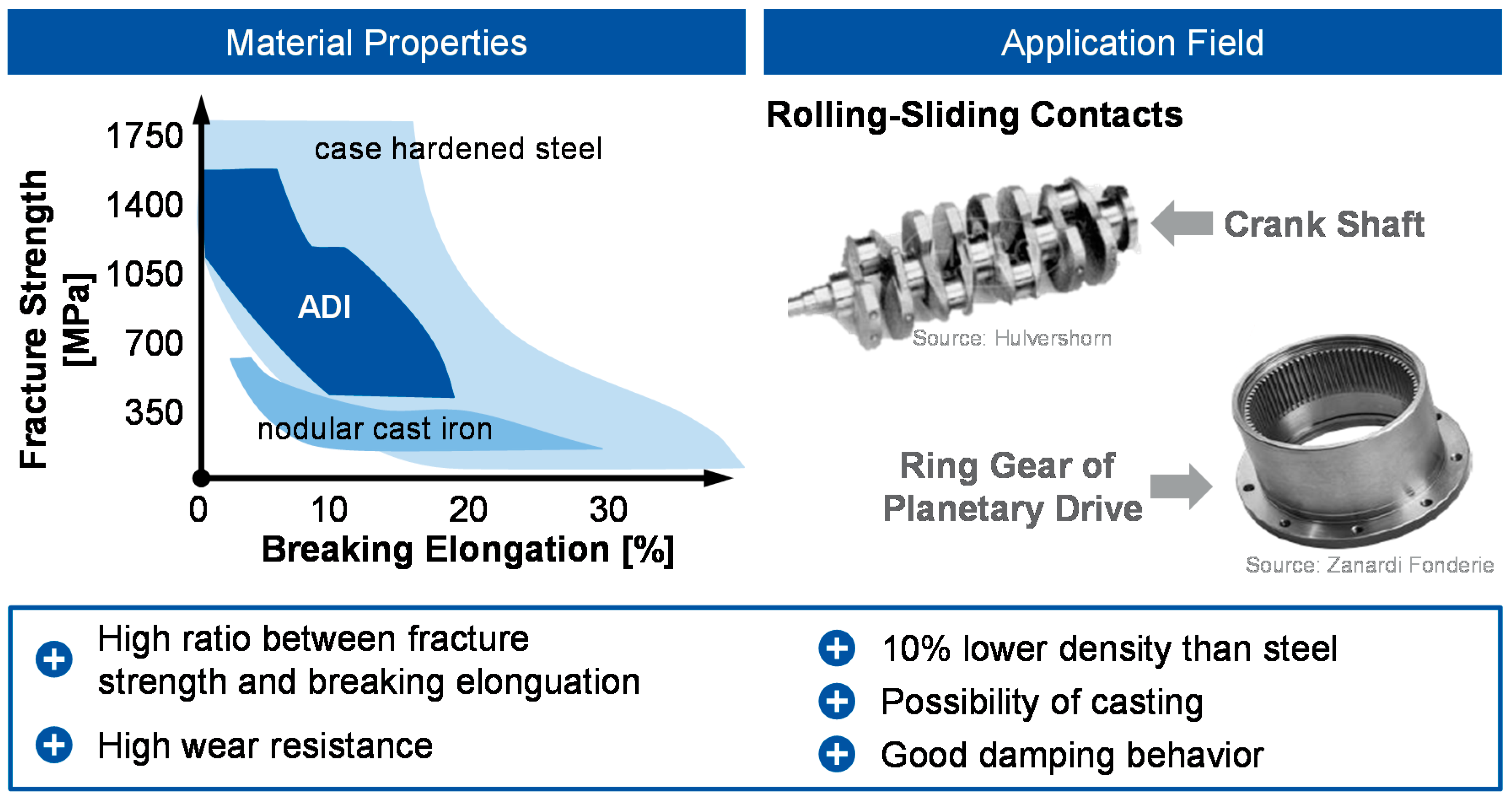
1. Introduction
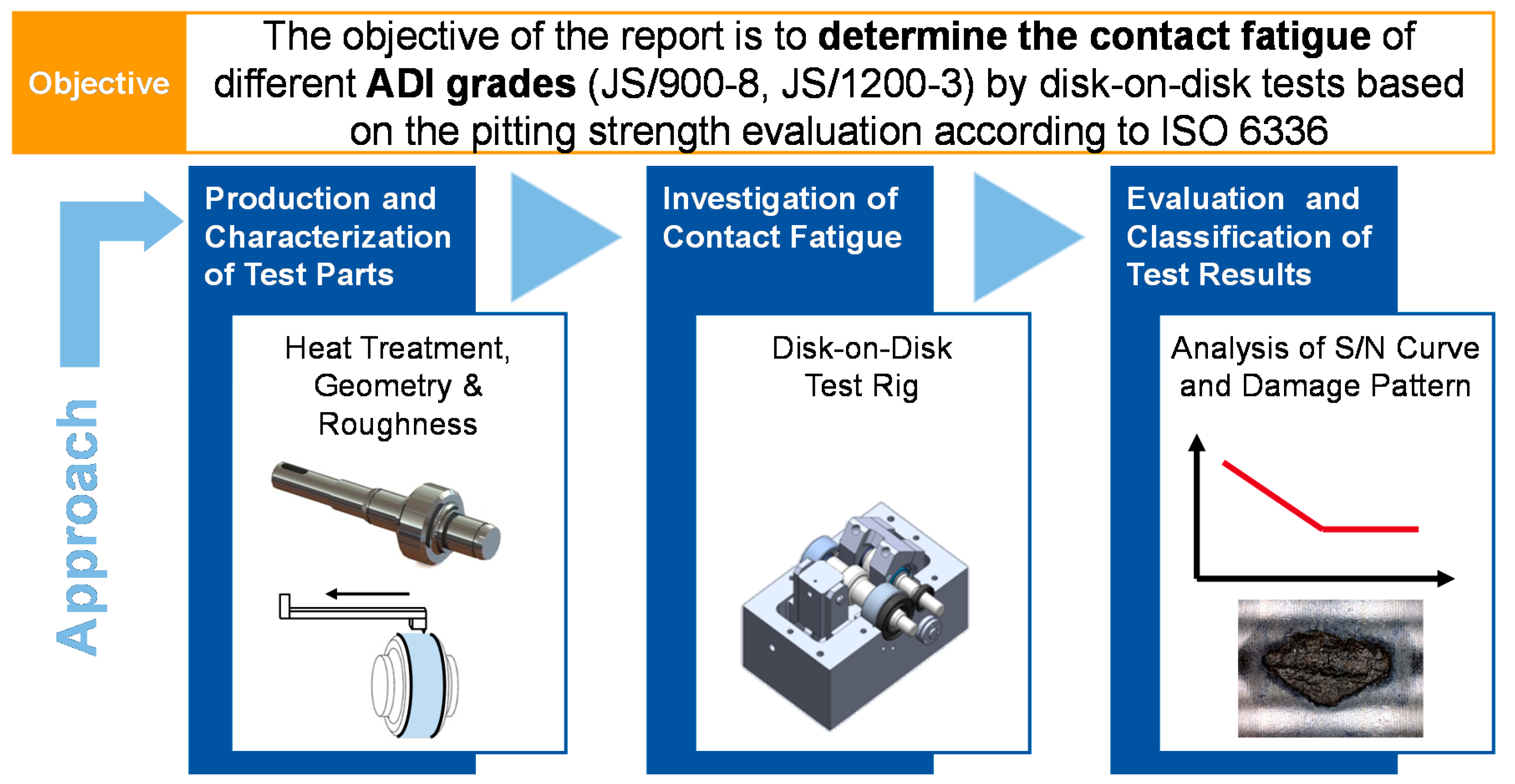
2. Objective and Approach
3. Test Parts, Test Rigs and Test Conditions
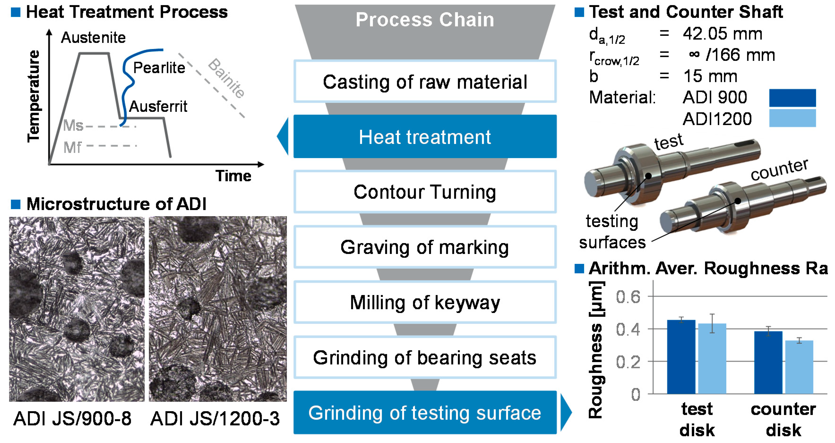
3.1. Test Parts
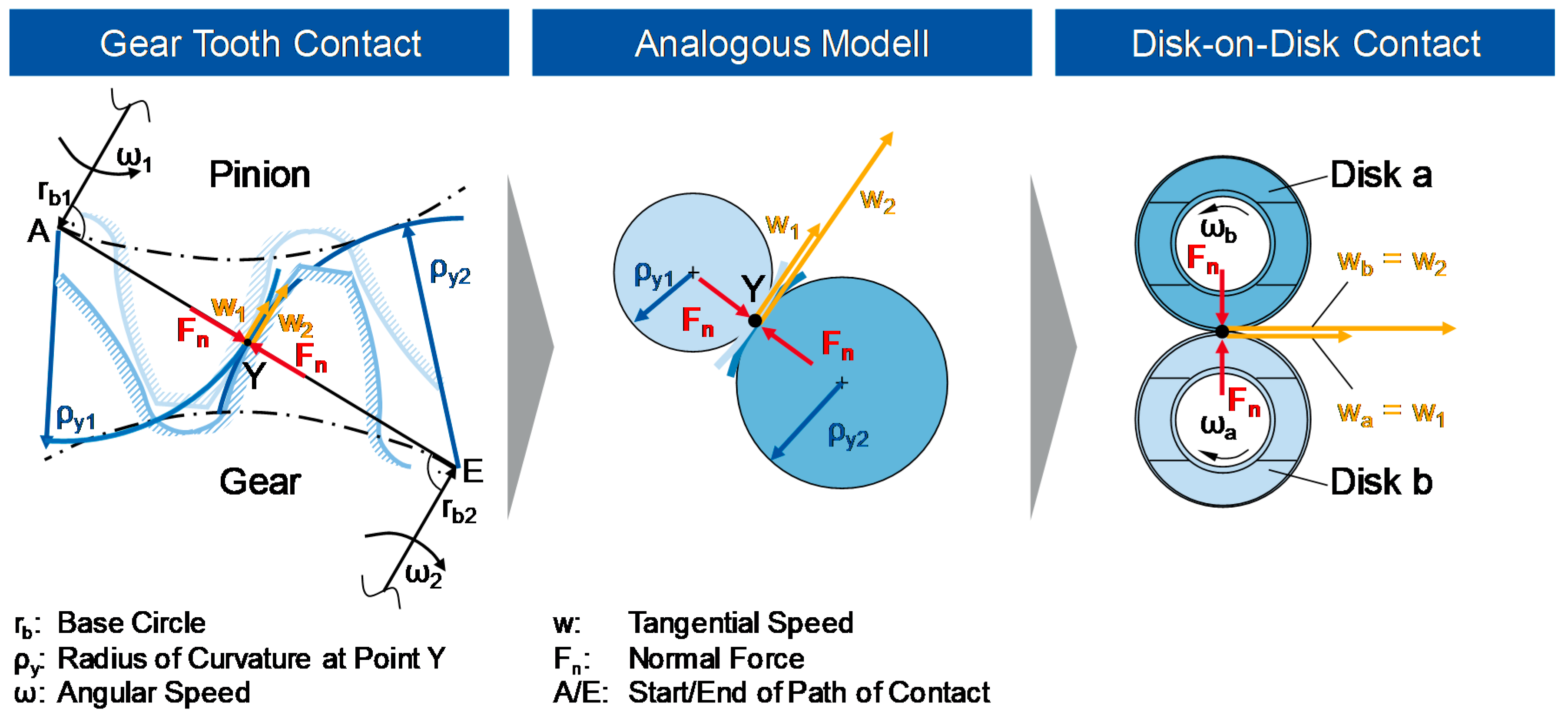
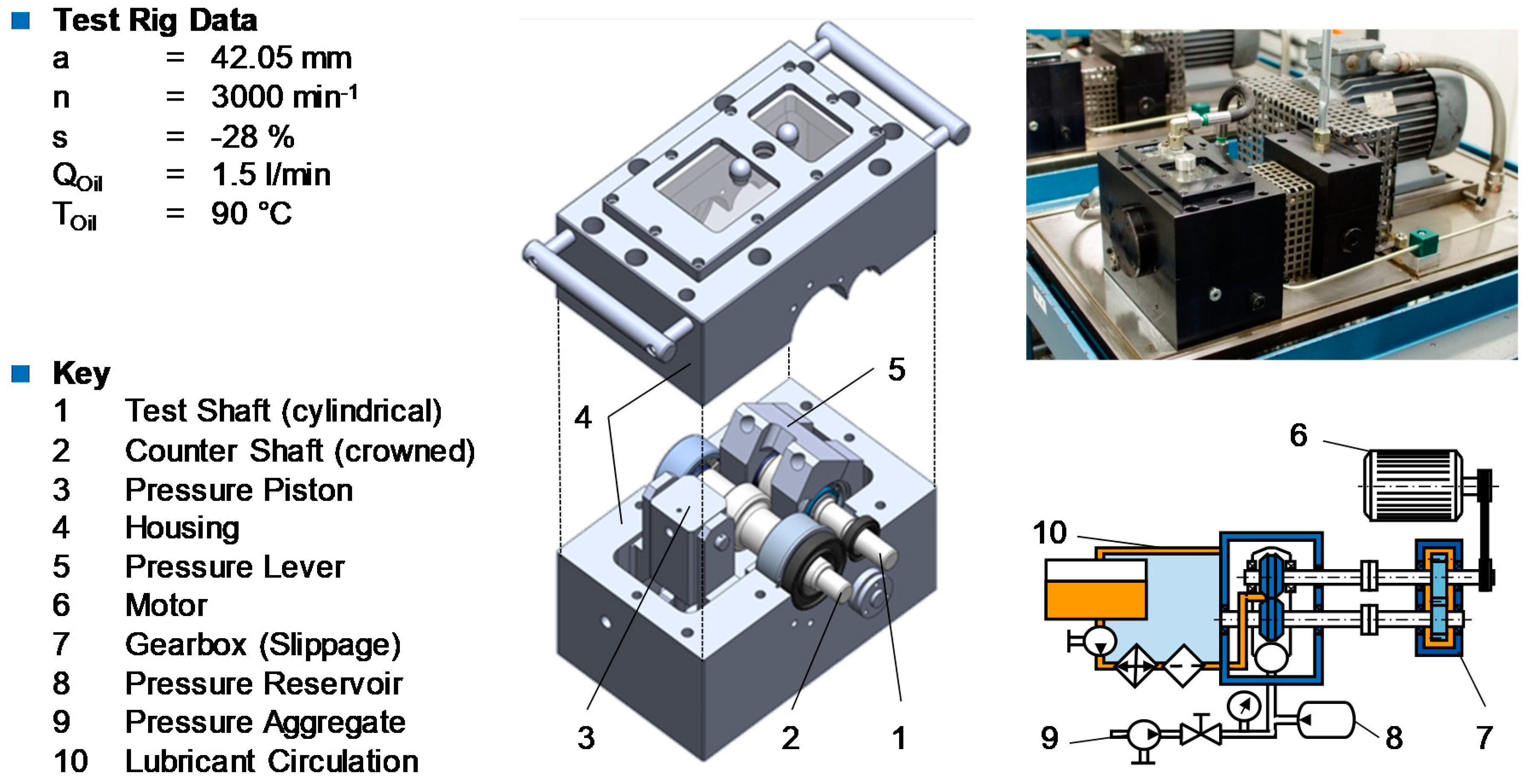
3.2. Test Rig and Test Conditions
4. Results and Discussion
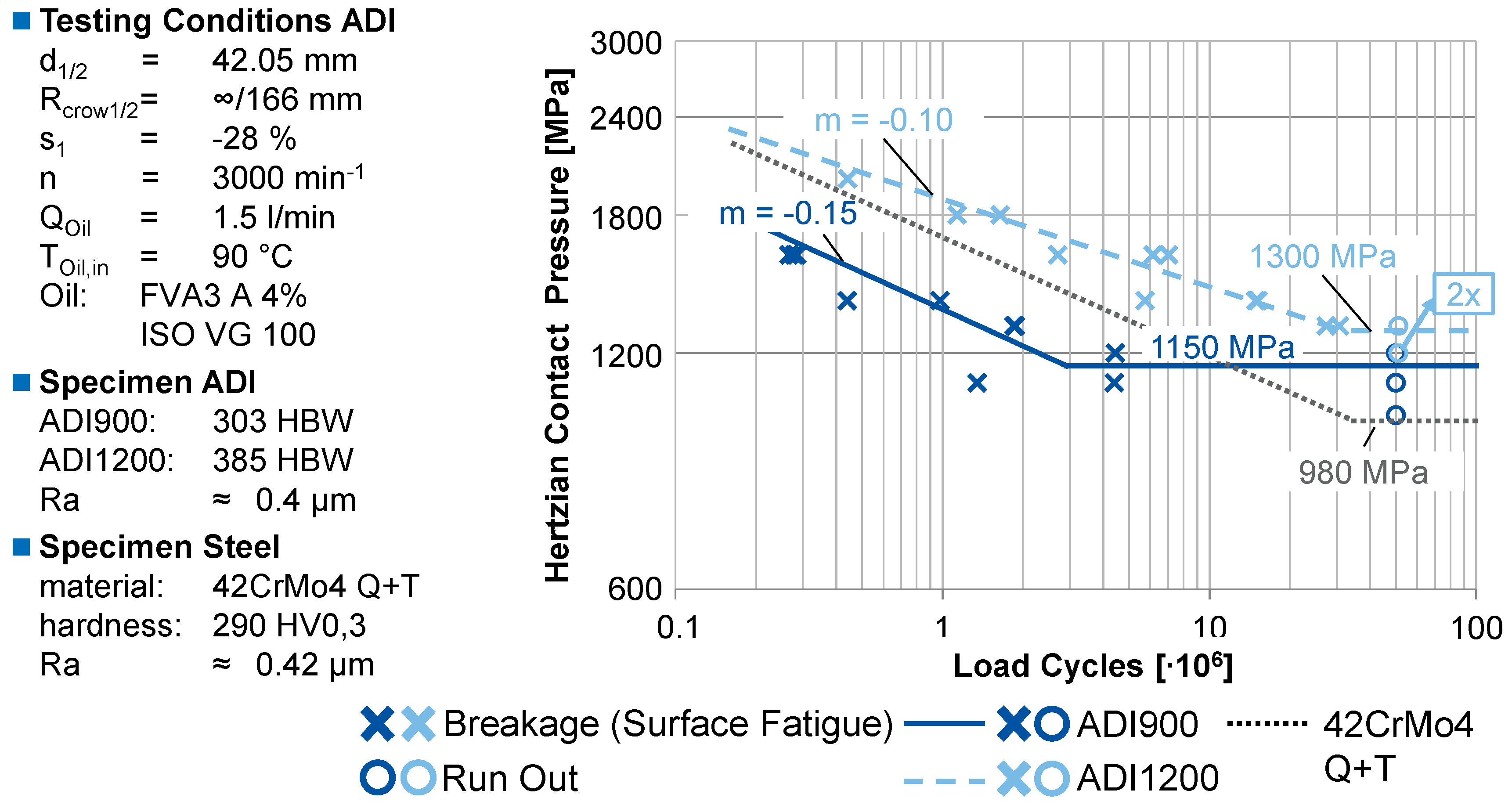
4.1. Contact Fatigue Strength
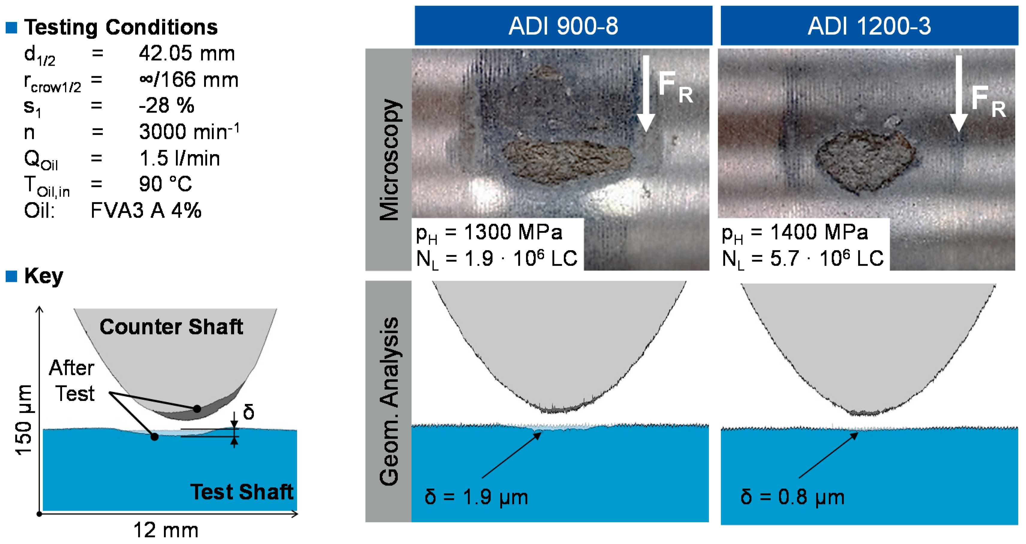
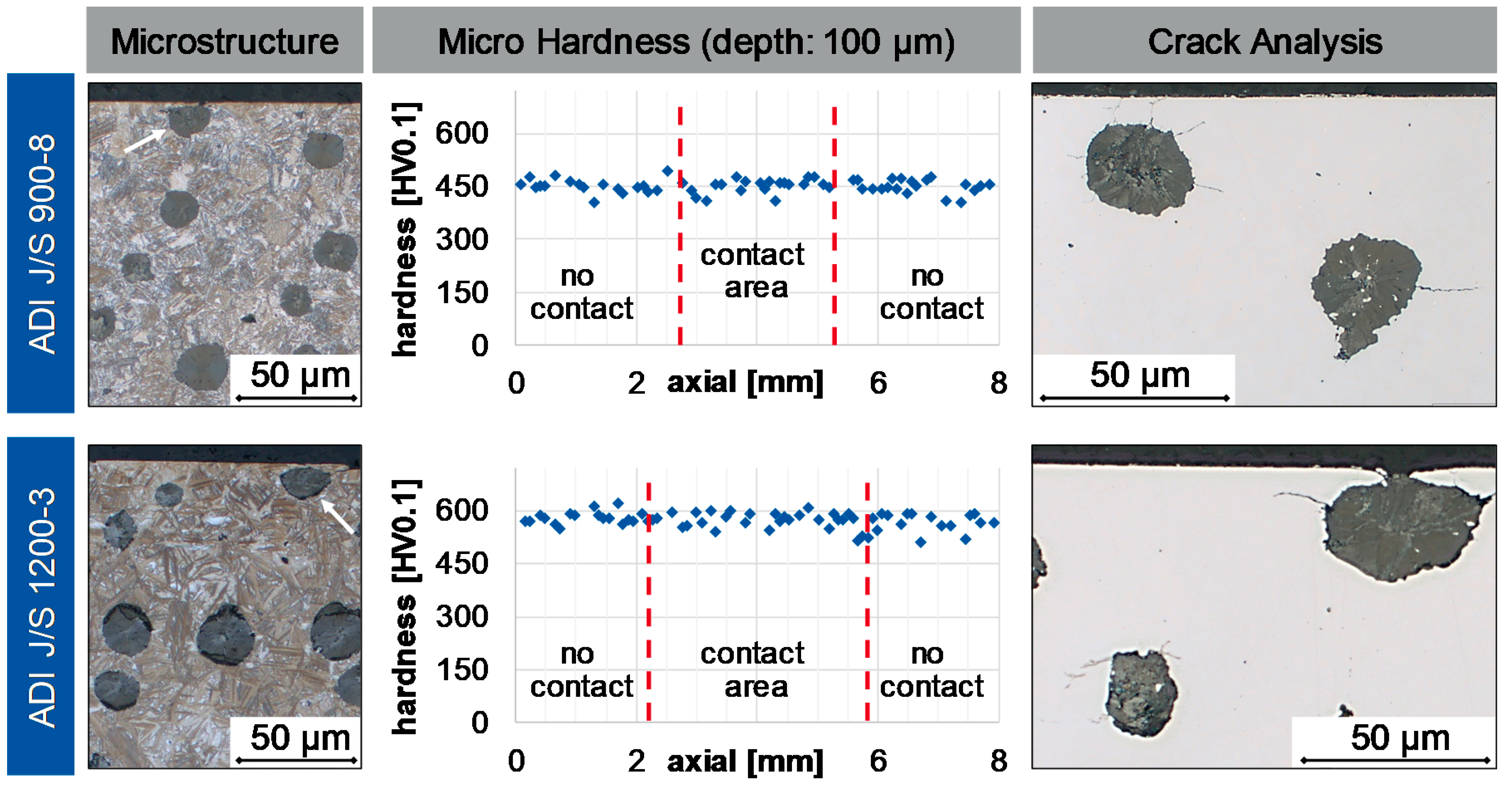
4.2. Pitting Characteristics and Microstructural Changes of ADI
5. Conclusions
Author Contributions
Funding
Conflicts of Interest
Appendix A

| Symbol | Unit | Definition |
|---|---|---|
| a | mm | Center distance |
| A | % | Fracture elongation |
| b | mm | Width of disk |
| da | mm | Outer diameter of disk |
| E | N/mm2 | Young’s modulus |
| FN | N | Normal force |
| FR | N | Friction force |
| HBW | - | Brinnell hardness |
| HV | - | Vickers hardness |
| m | - | Slope of time yield straight |
| mn | mm | Normal module |
| n | min−1 | Rotational speed |
| N | - | Number of load cycles |
| pH | MPa | Hertzian contact pressure |
| Q | min−1 | Volume flow rate |
| rcrown | mm | Radius of disk crowning |
| rb | mm | Base circle radius |
| Ra | µm | Arithmetical average roughness |
| Rz | µm | Average peak-to-valley height |
| Rm | N/mm2 | Tensile strength |
| Rp0.2 | N/mm2 | Yield strength |
| s | % | Slippage |
| t | µm | Depth |
| T | °C | Temperature |
| w | m/s | Tangential speed |
| z1/2 | - | Number of teeth |
| αn | ° | Normal pressure angle |
| δ | µm | Amount of plasticdeformation of disk |
| ν | - | Poisson’s ratio |
| ρ | mm | Radius of curvature |
| ω | s−1 | Angular speed |
References
- Zimba, J.; Simbi, D.J.; Navara, E. Austempered Ductile Iron: An Alternative Material for Earth Moving Components. Cem. Concr. Compos. 2003, 25, 643–649. [Google Scholar] [CrossRef]
- Wittwer, U.; Rechsteiner, A. ADI—Ein moderner Werkstoff mit vielfältigem Potenzial. Cast. J. 2005, 18, 4–6. [Google Scholar]
- Lefevre, J.; Hayrynen, K.L. Austempered Materials for Powertrain Applications. J. Mater. Eng. Perform. 2013, 22, 1914–1922. [Google Scholar] [CrossRef]
- Magalhaes, L.; Seabra, J.; Sá, C. Contact fatigue behaviour of artificially indented austempered ductile iron (ADI) discs. Tribol. Ser. 2001, 39, 469–482. [Google Scholar]
- Dommarco, R.C.; Bastias, P.C.; Dall’O, H.A.; Hahn, G.T.; Rubin, C.A. Rolling Contact Fatigue (RCF) resistance of Austempered Ductile Iron (ADI). Wear 1998, 221, 69–74. [Google Scholar] [CrossRef]
- Duarte, A.; Seabra, J.; Santos, H.M.C.M. ADI Behaviour under Twin-Disc Contact Fatigue Tests. Key Eng. Mater. 2002, 230, 218–221. [Google Scholar] [CrossRef]
- Standard. Gießereiwesen—Ausferritisches Gusseisen Mit Kugelgraphit; DIN 1564; Beuth: Berlin, Germany, 2012. [Google Scholar]
- Keough, J.R.; Lefevre, J. It Is Time to Include Austempered Ductile Iron (ADI) in the International Gear Standards; 2013; pp. 1–15. [Google Scholar]
- Standard. Austempered Ductile Iron for Gears; AGMA 939-A07; American Gear Manufacturers Association: Alexandria, VA, USA, 2007. [Google Scholar]
- Nofal, A. ADI—The New Dream Material for Gear Designers. In Proceedings of the 71st World Foundry Congress, Bilbao, Spain, 19–21 May 2014. [Google Scholar]
- Standard. Calculation of Load Capacity of Spur and Helical Gears—Part 2: Calculation of Surface Durability (Pitting); ISO 6336 Part 2; ISO Copyright Office: Geneva, Switzerland, 2008. [Google Scholar]
- Standard. Calculation of Load Capacity of Spur and Helical Gears—Part 5: Strength and Quality of Materials; ISO 6336 Part 5; ISO Copyright Office: Geneva, Switzerland, 2015. [Google Scholar]
- Hück, M. Ein verbessertes Verfahren für die Auswertung von Treppenstufenversuchen. Werkstofftechnik 1983, 24, 406–417. [Google Scholar] [CrossRef]
- Lebensdauerstatistik. Statistische Methoden zur Beurteilung von Bauteillebensdauer und Zuverlässigkeit und ihre Beispielhafte Anwendung auf Zahnräder; Höhn, B.-R., Zenner, H., Eds.; FVA (Forschungsvereinigung Antriebstechnik e.V.): Frankfurt, Germany, 1999. [Google Scholar]
- Standard. Founding—Ausferritic Spheroidal Graphite Cast Irons—Classification; ISO 17804; ISO Copyright Office: Geneva, Switzerland, 2005. [Google Scholar]
- Bagh, A. Auslegung PVD-Beschichteter Stirnräder. Ph.D. Thesis, RWTH Aachen University, Aachen, Germany, 2015. [Google Scholar]
- Bugiel, C. Tribologisches Verhalten und Tragfähigkeit PVD-Beschichteter Getriebe-Zahnflanken. Ph.D. Thesis, RWTH Aachen University, Aachen, Germany, 2009. [Google Scholar]
- Löpenhaus, C. Untersuchung und Berechnung der Wälzfestigkeit im Scheiben-und Zahnflankenkontakt. Ph.D. Thesis, RWTH Aachen University, Aachen, Germany, 2015. [Google Scholar]
- Gohritz, A. Ermittlung der Zahnflankentragfähigkeit Mittlerer und Grosser Getriebe durch Analogieversuche. Ph.D. Thesis, RWTH Aachen University, Aachen, Germany, 1982. [Google Scholar]
- Börnecke, K. Beanspruchungsgerechte Wärmebehandlung von Einsatzgehärteten Zylinderrädern. Ph.D. Thesis, RWTH Aachen University, Aachen, Germany, 1976. [Google Scholar]
- Empfehlungen zur Vereinheitlichung von Tragfähigkeitsversuchen an Vergüteten und Gehärteten Zylinderrädern; Stahl, K., Tobie, T., Matt, P., Eds.; FVA (Forschungsvereinigung Antriebstechnik e.V.): Frankfurt, Germany, 2012. [Google Scholar]
- Tobie, T. Zur Grübchen- und Zahnfusstragfähigkeit Einsatzgehärteter Zahnräder: Einflüsse aus Einsatzhärtungstiefe, Wärmebehandlung und Fertigung bei Unterschiedlicher Baugröße. Ph.D. Thesis, TU München, München, Germany, 2001. [Google Scholar]
- Klocke, F.; Brecher, C. Zahnrad- und Getriebetechnik. Auslegung-Herstellung-Untersuchung-Simulation, 1st ed.; Carl Hanser: München, Germany, 2017; ISBN 9783446430686. [Google Scholar]
- Ding, Y.; Gear, J.A. Spalling depth prediction model. Wear 2009, 267, 1181–1190. [Google Scholar] [CrossRef]
- Elstorpff, M.-G. Einflüsse auf die Grübchentragfähigkeit Einsatzgehärteter Zahnräder bis in das Höchste Zeitfestigkeitsgebiet. Ph.D. Thesis, TU München, München, Germany, 1993. [Google Scholar]
- Liu, J. Weakest link theory and multiaxial criteria. In Proceedings of the 5th International Conference on Biaxial/Multiaxial Fatigue and Fracture, Crakow, Poland, 8–12 September 1997; pp. 45–62. [Google Scholar]
- Liu, J. Beitrag zur Verbesserung der Dauerfestigkeitsberechnung bei Mehrachsiger Beanspruchung. Ph.D. Thesis, TU Clausthal, Clausthal-Zellerfeld, Germany, 1991. [Google Scholar]


| Carbon | Silicon | Manganese | Copper | Nickel | Molybdenum |
|---|---|---|---|---|---|
| C [wt.%] | Si [wt.%] | Mn [wt.%] | Co [wt.%] | Ni [wt.%] | Mo [wt.%] |
| 3.56 | 2.44 | 0.20 | 0.65 | 1 | 0.26 |
| Material Grade | Tensile Strength | Yield Strength | Frac. Elongation | Brinnell Hardn. |
|---|---|---|---|---|
| ISO17804 [15] | Rm [N/mm2] | RP0.2 [N/mm2] | A5 [%] | HBW |
| ADI JS/900-8C | 925 | 723 | 8.2 | 294–311 |
| ADI JS/1200-3C | 1241 | 945 | 4.1 | 378–392 |
© 2020 by the authors. Licensee MDPI, Basel, Switzerland. This article is an open access article distributed under the terms and conditions of the Creative Commons Attribution (CC BY) license (http://creativecommons.org/licenses/by/4.0/).
Share and Cite
Goergen, F.; Mevissen, D.; Masaggia, S.; Veneri, E.; Brimmers, J.; Brecher, C. Contact Fatigue Strength of Austempered Ductile Iron (ADI) in Gear Applications. Metals 2020, 10, 1147. https://doi.org/10.3390/met10091147
Goergen F, Mevissen D, Masaggia S, Veneri E, Brimmers J, Brecher C. Contact Fatigue Strength of Austempered Ductile Iron (ADI) in Gear Applications. Metals. 2020; 10(9):1147. https://doi.org/10.3390/met10091147
Chicago/Turabian StyleGoergen, Fabian, Dieter Mevissen, Stefano Masaggia, Enrico Veneri, Jens Brimmers, and Christian Brecher. 2020. "Contact Fatigue Strength of Austempered Ductile Iron (ADI) in Gear Applications" Metals 10, no. 9: 1147. https://doi.org/10.3390/met10091147
APA StyleGoergen, F., Mevissen, D., Masaggia, S., Veneri, E., Brimmers, J., & Brecher, C. (2020). Contact Fatigue Strength of Austempered Ductile Iron (ADI) in Gear Applications. Metals, 10(9), 1147. https://doi.org/10.3390/met10091147