Annealing-Induced Changes in the Microstructure and Mechanical Response of a Cu Nanofoam Processed by Dealloying

 , ,
, , 
Abstract
1. Introduction
2. Materials and Methods
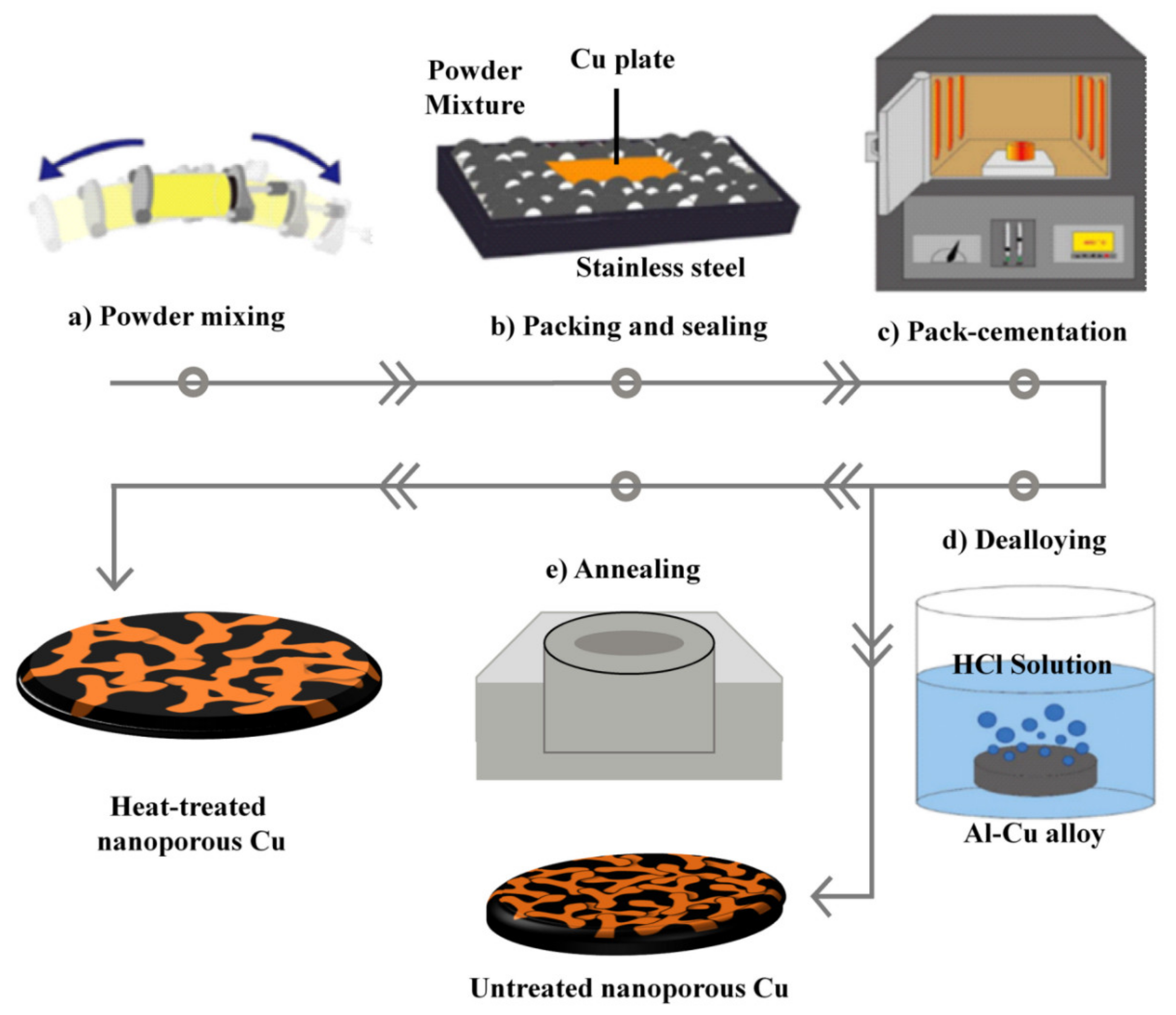
2.1. Synthesis of Nanoporous Cu
2.2. Characterization of the Microstructure
2.3. Hardness Testing
3. Results and Discussion
4. Conclusions
Author Contributions
Funding
Conflicts of Interest
References
- Goodenough, J.B.; Gao, H. A perspective on the Li-ion battery. Sci. China Chem. 2019, 62, 1555–1556. [Google Scholar] [CrossRef]
- Poizot, P.; Laruelle, S.; Grugeon, S.; Dupont, L.; Tarascon, J.M. Nano-sized transition-metal oxides as negative-electrode materials for lithium-ion batteries. Nature 2000, 407, 496. [Google Scholar] [CrossRef] [PubMed]
- Etacheri, V.; Marom, R.; Elazari, R.; Salitra, G.; Aurbach, D. Challenges in the development of advanced Li-ion batteries: A review. Energy Environ. Sci. 2011, 4, 3243. [Google Scholar] [CrossRef]
- Sawai, K.; Iwakoshi, Y.; Ohzuku, T. Carbon materials for lithium-ion (shuttlecock) cells. Solid State Ion. 1994, 69, 273–283. [Google Scholar] [CrossRef]
- Ji, L.; Lin, Z.; Alcoutlabi, M.; Zhang, X. Recent developments in nanostructured anode materials for rechargeable lithium-ion batteries. Energy Environ. Sci. 2011, 4, 2682–2699. [Google Scholar] [CrossRef]
- Jiang, J.; Li, Y.; Liu, J.; Huang, X.; Yuan, C.; Lou, X.W. Recent Advances in Metal Oxide-based Electrode Architecture Design for Electrochemical Energy Storage. Adv. Mater. 2012, 24, 5166. [Google Scholar] [CrossRef]
- Han, G.; Um, J.H.; Park, H.; Hong, K.; Yoon, W.S.; Choe, H. Hierarchically structured nanoporous copper for use as lithium-ion battery anode. Scripta Mater. 2019, 163, 9–13. [Google Scholar] [CrossRef]
- Jo, H.; Kim, M.J.; Choi, H.; Sung, Y.-E.; Choe, H.; Dunand, D.C. Morphological study of directionally freeze-cast nickel foams. Metall. Mater. Trans. E 2016, 3, 46–54. [Google Scholar] [CrossRef]
- Wang, Z.; Su, F.; Madhavi, S.; Lou, X.H. CuO Nanostructures supported on Cu substrate as integrated electrodes for highly reversible lithium storage. Nanoscale 2011, 3, 1618–1623. [Google Scholar] [CrossRef]
- Zou, L.; Gan, L.; Kang, F.; Wang, M.; Shen, W.; Huang, Z. Sn/C non-woven film prepared by electrospinning as anode materials for lithium ion batteries. J. Power Sources 2010, 195, 1216–1220. [Google Scholar] [CrossRef]
- Sun, L.; Chien, C.L.; Searson, P.C. Fabrication of nanoporous nickel by electrochemical dealloying. Chem. Mater. 2004, 16, 3125. [Google Scholar] [CrossRef]
- Park, H.; Um, J.H.; Choi, H.; Yoon, W.S.; Sung, Y.E.; Choe, H. Hierarchical micro-lamella-structured 3D porous copper current collector coated with tin for advanced lithium-ion batteries. Appl. Surf. Sci. 2017, 399, 132–138. [Google Scholar] [CrossRef]
- Lee, S.; Tam, J.; Li, W.; Yu, B.; Cho, H.J.; Samei, J.; Wilkinson, D.S.; Choe, H.; Erb, U. Multi-scale morphological characterization of Ni foams with directional pores. Mater. Charact. 2019, 158, 109939. [Google Scholar] [CrossRef]
- Ribárik, G.; Gubicza, J.; Ungár, T. Correlation between strength and microstructure of ball-milled Al–Mg alloys determined by X-ray diffraction. Mater. Sci. Eng. A 2004, 387–389, 343–347. [Google Scholar]
- Gubicza, J. X-Ray Line Profile Analysis in Materials Science; IGI-Global: Hershey, PA, USA, 2014. [Google Scholar]
- Liu, W.; Zhang, S.; Li, N.; Zheng, J.; An, S.; Li, G. Influence of Dealloying Solution on the Microstructure of Monolithic Nanoporous Copper through Chemical Dealloying of Al 30 at.% Cu Alloy. Int. J. Electrochem. Sci. 2012, 7, 7993–8006. [Google Scholar]
- Viswanathan, V.; Laha, T.; Balani, K.; Agarwal, A.; Seal, S. Challenges and advances in nanocomposite processing techniques. Mater. Sci. Eng. R 2006, 54, 121–285. [Google Scholar] [CrossRef]
- Fan, Z.; Miodownil, A.P.; Tsakiropoulos, P. Microstructural characterisation of two phase materials. J. Mater. Sci. Technol. 2013, 7, 1094–1100. [Google Scholar] [CrossRef]
- Jo, H.; Cho, Y.H.; Choi, M.; Cho, J.; Um, J.H.; Yung-Eun Sung, Y.E.; Choe, H. Novel method of powder-based processing of copper nanofoams for their potential use in energy applications. Mater. Chem. Phys. 2014, 145, 6–11. [Google Scholar] [CrossRef]
- Li, T.; Ngô, B.N.D.; Markmann, J.; Weissmuller, J. Topology evolution during coarsening of nanoscale metal network structures. Phys. Rev. Mater. 2019, 3, 076001. [Google Scholar] [CrossRef]
- Liu, L.; Ye, X.; Jin, H. Interpreting anomalous low-strength and low-stiffness of nanoporous gold: Quantification of network connectivity. Acta Mater. 2016, 18, 77–87. [Google Scholar] [CrossRef]
- Sun, Y.; Balk, J. A multi-step dealloying method to produce nanoporous gold with no volume change and minimal cracking. Scr. Mater. 2008, 58, 727–730. [Google Scholar] [CrossRef]
- Geslin, P.; Buchet, M.; Wada, T.; Kato, H. Phase-field investigation of the coarsening of porous structures by surface diffusion. Phys. Rev. Mater. 2019, 3, 083401. [Google Scholar] [CrossRef]
- Herring, C. Effect of Change of Scale on Sintering Phenomena. J. Appl. Phys. 1949, 16, 301–303. [Google Scholar] [CrossRef]
- Um, T.; Wilke, S.K.; Choe, H.; Dunand, D.C. Effects of pore morphology on the cyclical oxidatio/-reduction of iron foams created via camphene-based freeze casting. J. Alloys. Compd. 2020, 845, 156278. [Google Scholar] [CrossRef]
- Nam, K.; Park, H.; Choe, H. Continuity as a governing parameter to predict the strength of porous materials. Mater. Lett. 2018, 214, 99–102. [Google Scholar] [CrossRef]
- Kolonits, T.; Czigány, Z.; Péter, L.; Bakonyi, I.; Gubicza, J. Influence of Bath Additives on the Thermal Stability of the Nanostructure and Hardness of Ni Films Processed by Electrodeposition. Coatings 2019, 9, 644. [Google Scholar] [CrossRef]
- Kapoor, G.; Péter, L.; Fekete, É.; Lábár, J.L.; Gubicza, J. The influence of Mo addition on the microstructure and its thermal stability for electrodeposited Ni films. Mater. Charact. 2018, 145, 563–572. [Google Scholar] [CrossRef]
- Nunes, A.C.; Lin, D. Effects of surface relaxation on powder diffraction patterns of very fine particles. J. Appl. Cryst. 1995, 28, 274–278. [Google Scholar] [CrossRef]
- Leoni, M.; Scardi, P. Grain surface relaxation effects in powder diffraction. In Diffraction Analysis of the Microstructure of Materials; Scardi, P., Mittemeijer, E.J., Eds.; Springer Science & Business Media: Berlin, Germany, 2004. [Google Scholar]
- Zhang, C.L.; Godfrey, A.; Zhang, Y.; Wu, G.L.; Xu, R.; Liu, W.; Juul Jensen, D. Dislocation density in fine grain-size spark-plasma sintered aluminum measured using high brightness synchrotron radiation. Mater. Lett. 2020, 269, 127653. [Google Scholar] [CrossRef]
- Gubicza, J. Characterization of glasses and ceramics by continuous indentation tests. Key Eng. Mater. 1995, 103, 217–220. [Google Scholar] [CrossRef]
- Biener, J.; Hodge, A.M.; Hayes, J.R.; Volkert, C.A.; Zepeda-Ruiz, L.A.; Hamza, A.V.; Abraham, F.F. Size Effects on the Mechanical Behavior of Nanoporous Au. Nano Lett. 2006, 6, 2379–2382. [Google Scholar] [CrossRef] [PubMed]
- Cox, M.E.; Dunand, D.C. Bulk gold with hierarchical macro-, micro- and nano-porosity. Mater. Sci. Eng. A 2011, 528, 2401–2406. [Google Scholar] [CrossRef]
- Chen-Wiegart, Y.K.; Wang, S.; Chu, Y.S.; Liu, W.; McNulty, I.; Voorhees, P.W.; Dunand, D.C. Structural evolution of nanoporous gold during thermal coarsening. Acta Mater. 2012, 60, 4972–4981. [Google Scholar] [CrossRef]


| Element | Initial | Heat Treated |
|---|---|---|
| O (at.%) | 5.6 ± 1.5 | 6.9 ± 0.8 |
| Al (at.%) | 3.2 ± 0.6 | 2.8 ± 0.1 |
| Cl (at.%) | 0.82 ± 0.14 | 0.63 ± 0.5 |
| Cu (at.%) | 90.3 ± 2.4 | 89.7 ± 0.7 |
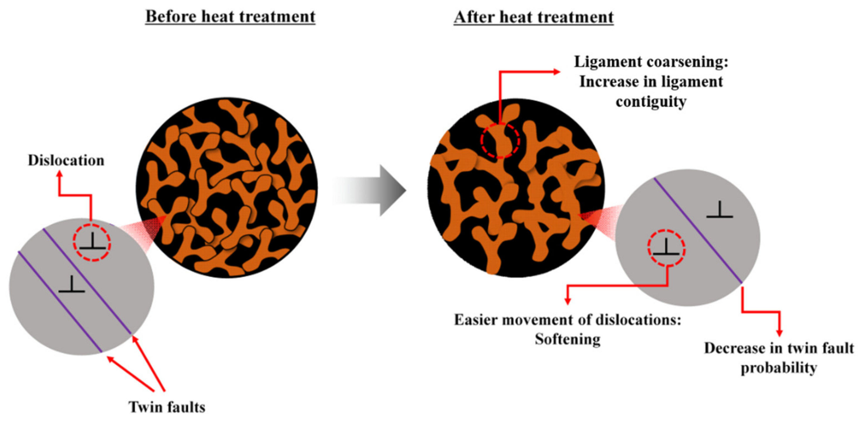
| Sample | Ligament Size (nm) | Diffraction Domain Size (nm) | Dislocation Density (1014 m−2) | Twin Fault Probability (%) |
|---|---|---|---|---|
| Initial | 105 ± 6 | 18 ± 4 | 4 ± 1 | 2.1 ± 0.2 |
| Heat-treated | 125 ± 6 | 142 ± 17 | 6 ± 1 | 1.0 ± 0.1 |
© 2020 by the authors. Licensee MDPI, Basel, Switzerland. This article is an open access article distributed under the terms and conditions of the Creative Commons Attribution (CC BY) license (http://creativecommons.org/licenses/by/4.0/).
Share and Cite
Jenei, P.; Kádár, C.; Han, G.; Hung, P.T.; Choe, H.; Gubicza, J. Annealing-Induced Changes in the Microstructure and Mechanical Response of a Cu Nanofoam Processed by Dealloying. Metals 2020, 10, 1128. https://doi.org/10.3390/met10091128
Jenei P, Kádár C, Han G, Hung PT, Choe H, Gubicza J. Annealing-Induced Changes in the Microstructure and Mechanical Response of a Cu Nanofoam Processed by Dealloying. Metals. 2020; 10(9):1128. https://doi.org/10.3390/met10091128
Chicago/Turabian StyleJenei, Péter, Csilla Kádár, Gigap Han, Pham Tran Hung, Heeman Choe, and Jenő Gubicza. 2020. "Annealing-Induced Changes in the Microstructure and Mechanical Response of a Cu Nanofoam Processed by Dealloying" Metals 10, no. 9: 1128. https://doi.org/10.3390/met10091128
APA StyleJenei, P., Kádár, C., Han, G., Hung, P. T., Choe, H., & Gubicza, J. (2020). Annealing-Induced Changes in the Microstructure and Mechanical Response of a Cu Nanofoam Processed by Dealloying. Metals, 10(9), 1128. https://doi.org/10.3390/met10091128