Article

Conductive Heating during Press Hardening by Hot Metal Gas Forming for Curved Complex Part Geometries

1
Fraunhofer Institute for Machine Tools and Forming Technology IWU, 09126 Chemnitz, Germany
2
Salzgitter Hydroforming Verwaltungs GmbH, 08451 Crimmitschau, Germany
*
Author to whom correspondence should be addressed.
Metals 2020, 10(8), 1104; https://doi.org/10.3390/met10081104
Submission received: 26 June 2020 / Revised: 28 July 2020 / Accepted: 14 August 2020 / Published: 17 August 2020
(This article belongs to the Special Issue Latest Hydroforming Technology of Metallic Tubes and Sheets)

Abstract

:
Climate targets set by the EU, including the reduction of CO2, are leading to the increased use of lightweight materials for mass production such as press hardening steels. Besides sheet metal forming for high-strength components, tubular or profile forming (Hot Metal Gas Forming—HMGF) allows for designs that are more complex in combination with a lower weight. This paper particularly examines the application of conductive heating of the component for the combined press hardening process. The previous Finite-Element-Method (FEM)-supported design of an industry-oriented, curved component geometry allows the development of forming tools and process peripherals with a high degree of reliability. This work comprises a description regarding the functionality of the tools and the heating strategy for the curved component as well as the measurement technology used to investigate the heat distribution in the component during the conduction process. Subsequently, forming tests are carried out, material characterization is performed by hardness measurements in relevant areas of the component, and the FEM simulation is validated by comparing the resulting sheet thickness distribution to the experimental one.

1. Introduction

According to Yang [1], vehicles and road transportation produce more than 20% of greenhouse gas emissions. Here, the use stage causes approximately 85% of a passenger car’s global warming potential [2]. In this phase, the vehicle weight is essential with regard to fuel consumption, therefore implementing lightweight design approaches is a key in order to reduce fuel consumption and CO2 emissions, respectively. Yang [1] shows that the CO2 emissions of new passenger cars have been steadily decreasing in the EU over the last 25 years. Nevertheless, additional effort is necessary in order to achieve the climate targets fixed by the EU, which include a 40% reduction of CO2 by 2030 compared to the state of 1990 [3]. Aspects of material and design must be optimized in order to minimize component weight. Material optimization includes the application of typical lightweight materials such as aluminum and magnesium alloys or composites. However, economic aspects also have to be taken into account, especially in mass production. In addition, the application of high-strength steels, including press hardening steels, is superior to the other lightweight materials [4]. Weight optimized design strategies such as structuring [5] or functional integration usually result in very complex geometries. Thus, innovative forming technologies are needed that are capable of producing demanding geometries from hardly formable materials. In automotive production, especially in the manufacturing of chassis components, press hardening (which is also referred to as hot stamping) of sheet metal is a well-established process which allows for the manufacturing of high-strength components with minimal springback [6]. However, when realizing complex components, the use of tubular or profile shaped semi-finished parts frequently allows replacing several sheet metal parts in total, leading to lower material use and consequently resulting in lower weight and high component stiffness. Hydroforming is a suitable technology here [7]. At the same time, joining operations can be eliminated from the process chain so that often the result is a shorter and more cost-efficient process chain, see [8], where complex titanium parts are superplastically formed by HMGF in such a way that complex manufacturing with several joining operations can be saved. An innovative process investigated at the Fraunhofer Institute for Machine Tools and Forming Technology (IWU) combines the advantages of both press hardening and hydroforming. In this process, a tube or hollow profile made of the typical press hardening steels such as 22MnB5 is heated to austenitizing temperature, and then an inner gas pressure is applied so that the part expands in the die cavity. This process is the so-called Hot Metal Gas Forming (HMGF). As soon as it aligns to the cold dies, the part cools down rapidly resulting in a martensitic microstructure [9]. The dies are water-cooled in order to guarantee sufficiently high cooling rates in the process. The principal feasibility of HMGF combined with press hardening is shown in [9].
Similar to the press hardening processes with sheet metal, heating can be realized in a furnace or by flames [10]. In this case, it is necessary to transfer the hot component to the forming die. The most important disadvantage is a temperature decrease of up to 200 K. Bach et al. [11] have shown that components, which were heated up to 950 °C (Ac3-point for usual press hardening steels) in the furnace, had a residual temperature of approx. 850 °C after transfer into the tool, and the forming temperature dropped further to 750 °C during the closing of the dies. This drop in temperature led to a reduction in the formability of the base material and thus to the impossibility of fully forming of complex component geometries due to previously occurring cracks. Furthermore, scaling occurs due to the exposure of the hot part to atmospheric conditions. Conductive heating of the component is an alternative to avoid this transfer and the related disadvantages [12]. The authors of [13] describe the combination of HMGF with integrated conductive heating and press hardening for straight parts. Bach et al. [11] apply it to a curved component made of Docol PHS 1800 by SSAB (official current name and abbreviation of the former name Svenskt Stål AB) [14] for the first time and reveal that the heating strategy must be adapted in order to achieve homogeneous temperature in the curved part. The possibility of forming extremely complicated geometries with a high degree of functional integration, as they are often required in the industrial sector, can, under certain circumstances, justify the effort of extended process time and more complex tools. Based on these described methods, the aim of the current paper is to provide deeper insight into the heating process. It describes the tooling, including the conductive heating equipment, presents the heating strategy and shows its influence on the temperature distribution in the part and on the resulting component properties, specifically hardness and distribution of wall thickness.

2. Forming Task

The FEM-Simulation and investigation of the HMGF process are based on a complex demonstrator part geometry shown in Figure 1. It was designed in order to operate in the maximum forming ranges of the material in trials. It features 66° bending, different representative cross-section geometries of vehicle components and secondary form elements frequently occurring in typical hydroforming parts. The input geometry for the hydroforming process is a pre-bent tube made of Docol PHS 1800 [14] from SSAB with an initial diameter of 57 mm and a wall thickness of 1.5 mm. Detailed information on the chemical compound of the used tube material is shown in Table 1.
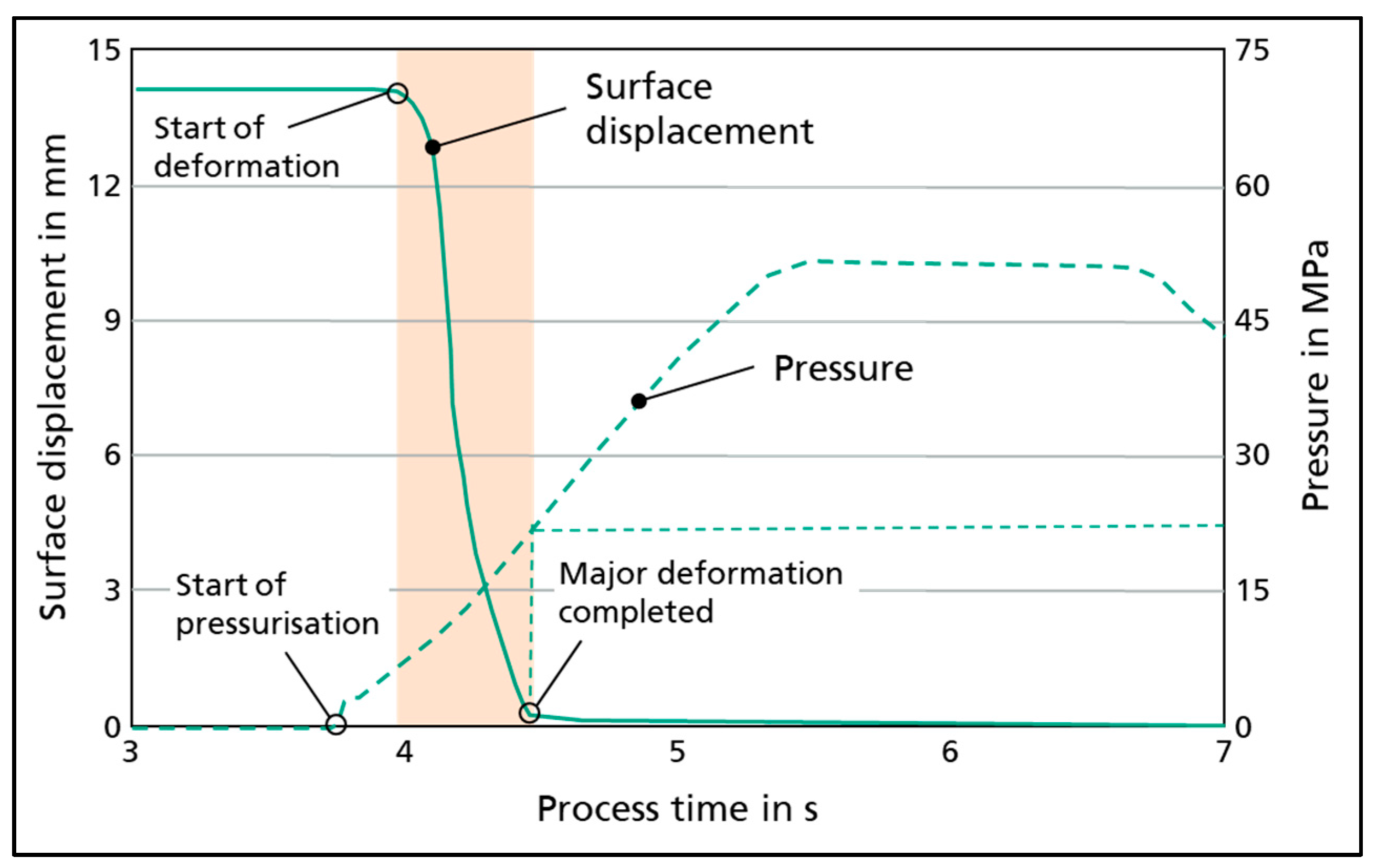
According to [14], the HMGF process is expected to bring the material to a tensile strength of 1800 MPa at a failure strain of 6%. In the delivery condition, the material has a tensile strength of 500 MPa at an elongation of 27%. A thermomechanical forming simulation was carried out using LS-Dyna in order to estimate the principal feasibility of the component and to draw conclusions for necessary geometry adjustments. Here, models with all relevant boundary conditions and sub-steps were taken into consideration as well as earlier investigation results. For example, the test results with regard to pressure curves and forming, with which parts have already been successfully produced, see Figure 2 [11], were taken as a basis. This figure shows the deformation of the test part in relation to the pressure curve. As shown, the decisive shaping of the component is already completed at an internal pressure of <25 MPa.
As usual for HMGF processes, also the tests within this study were carried out without axial feeding. The ends of the tube were fixed and simultaneously sealed by conical wedge elements. This sealing concept allows achieving high internal pressure. Approaches that work with axial feeding e.g., via a stepped sealing edge [15] the danger of leakage is high.
The achievement of the Ac3 point of the tested material is mandatory for the calculation of the functionality of the process chain and the achievement of the desired material properties. In order to achieve a pragmatic and simplified representation of the HMGF process with sufficient accuracy, the simulation of the heating of the component has been omitted. Uniform temperature distribution in the component was assumed at the beginning of the thermomechanical-coupled simulation although during the experiments to heat the real component, locally different temperatures were expected due to its geometry. This circumstance is counteracted with the concept of pulsed power supply, see Section 4, in order to reach the Ac3 point, in this case, 911 °C, at any point.
For the thermomechanical forming simulation, flow curve data was generated from tensile tests at seven different temperatures (950, 900, 850, 800, 750, 680, 600 °C) and for three different strain rates (0.5, 5, 50 s−1). The individual derived and extrapolated flow curves were implemented into a temperature and strain rate-dependent isotropic material model in LS-DYNA.
In the simulation model, the tools were implemented in the form of rigid active surface meshes. In contrast, the tube was represented as an elastically plastically deformable shell with an initial element edge length of 0.75 mm and five integration points across the thickness. In the starting situation of the forming simulation, the tempered tube was positioned in the tool. The following sub-simulations up to the actual forming stage ensured representation of the process-specific boundary conditions in which the semi-finished product already cools down after conductive heating. This included the calculation of the time required to close the upper die, start up the sealing punches and apply the closing force onto the tool halves. Within these simulations, the heat transfer mechanisms heat conduction, heat transfer to air by convection and radiation as well as contact heat transfer to the cooled tool surfaces were taken into account based on [16]. In the subsequent simulation of the pressure generation phase, the forming of the semi-finished product in the tool cavity was realized by stepwise, linear application of a pressure load to the inner surface of the tube up to the target pressure level. A constant static coefficient of friction of µ = 0.35 was assumed in the entire simulation steps, with which good experience has already been gained in previous work on the subject of tempered tube forming processes [11].
Results of the numerical simulation show that the circumferential expansion reaches values similar to a straight demonstrator regarded in earlier investigations [1], which could be successfully formed. Furthermore, the simulation predicts a minimum thickness of the tube material of approx. 0.85 mm after forming (Figure 3) which corresponds to a maximum thinning of 43.3%. This is also comparable with the successfully formed straight demonstrator mentioned above so that the currently regarded curved part can be expected to be feasible, too. However, it must be considered that the simulation disregards the strain results of the cold bending step, which is necessary before the HMGF process in order to allow positioning of the part in the hydroforming tool. This bending results in additional strain on the weld seam, but the corresponding impact on the resulting wall thickness distribution is expected to be small. This means that it was avoided to make the additional effort for implementing this preforming step in the numerical modeling for pragmatic reasons. Results of previous projects have shown that feasibility of hydroforming processes with pre-bent semi-finished parts will be the least affected if the weld seam is placed in the area of the neutral fiber and in zones featuring minor deformation during hydroforming. In the present case, this implies that the bottom of the component opposite of the dome is the most appropriate area for positioning the weld seam. Nevertheless, practical tests are indispensable in order to verify the simulation and to finally evaluate the feasibility.

3. Tool Concept and Measurement Technique

For the experimental verification of the numerical simulation and the final proof of feasibility of the part, a tool was designed, which can be applied under conditions that are close to series production. As shown in Figure 4, this tool consists of
  • The form elements providing the desired shape of the component with integrated cooling channels that are necessary to prevent accumulated heating of the dies over a number of tests; these elements are highlighted in Figure 4b,
  • The electrodes for conduction heating, which are highlighted in Figure 4c,
  • Guiding elements and force absorption elements, required for the functionality of the forming process, which are highlighted in Figure 4d,
  • Axial punches, sealing the tube and applying the inner gas pressure, see overview in Figure 4a,
  • An ejector that prevents the bending area from tilting into the tool engraving, see the green dot in the middle of the tool engraving in Figure 4c.
The electrodes are electrically insulated from the surrounding form inserts and spring-loaded so that they rise from the top and bottom when the tool is not completely closed. At the beginning of the process, the curved semi-finished part is clamped in these electrodes and lifted from the form inserts by the springs. Therefore, the part is electrically insulated from the metallic die elements so that the electrical current enters the tube at the electrode at one end and flows through the tube to the second electrode at the other end. The temperature of the tube rises due to resistive heating. As soon as the target temperature of the tube is reached and the tool halves start to get closed, the current is interrupted by an initiator. When the tool halves are closed, the axial punches seal the tube ends and the gas pressure is applied, leading to an expansion of the tube. All forming dies and electrodes are steadily water-cooled. In order to provide optimum cooling conditions, cooling channels must be located in direct proximity to the mold.
In general, the main application problem is gross cracking of the inserts due to insufficient toughness of the material if thermal shock occurs during the process. However, the mechanical strength of the tools and the leak tightness of the system must be guaranteed at the same time. A minimal distance between cooling channels and mold is required due to this fact. Extensive measurement technology was necessary for the thermal characterization of the component and process control. This measuring technology included a thermal camera, two pyrometers and type K thermocouples with direct measuring functions. The thermal camera (black in the lower part of Figure 5), whose orientation towards the component, provided detailed information about the local temperature distribution in the part at specific moments during the process. This information was used in the process analysis in order to characterize the overall heating behavior of the part and to identify relevant points of the workpiece, where more detailed information was needed and which were most suitable for process control. This measurement was complemented by the thermocouples and the pyrometers, which provided detailed information about the temperature as a function of the time for distinct points of the workpiece. The thermocouples served for analyzing the component heating behavior at six points in different regions of the part. However, due to the mechanical impact, this measurement technique turned out to be not suitable for reliable process control with the complete closing of the tool and the entire forming process. Therefore, contact-free optical measurement via pyrometers was used to control the conduction heating of the component at the two most relevant points.

4. Heating Procedure

The thermal camera is directed towards the outer area of the pre-bent workpiece. Figure 6 shows the temperature of the part at different moments during the heating process (specifically after 30 s, left, after 50 s, middle) and the real component on the right.
Obviously, only the middle section of the tube is visible since the component is partially covered by the tool halves that are not completely closed. In order to indicate the extent of the hidden sections, a dashed line represents the true contour of the part. After 50 s, large areas of the part reached the target temperature of 911 °C as assumed in the previous simulation. This especially concerns the straight end regions, while the temperature of the outer curved area is approx. 100 °C lower.
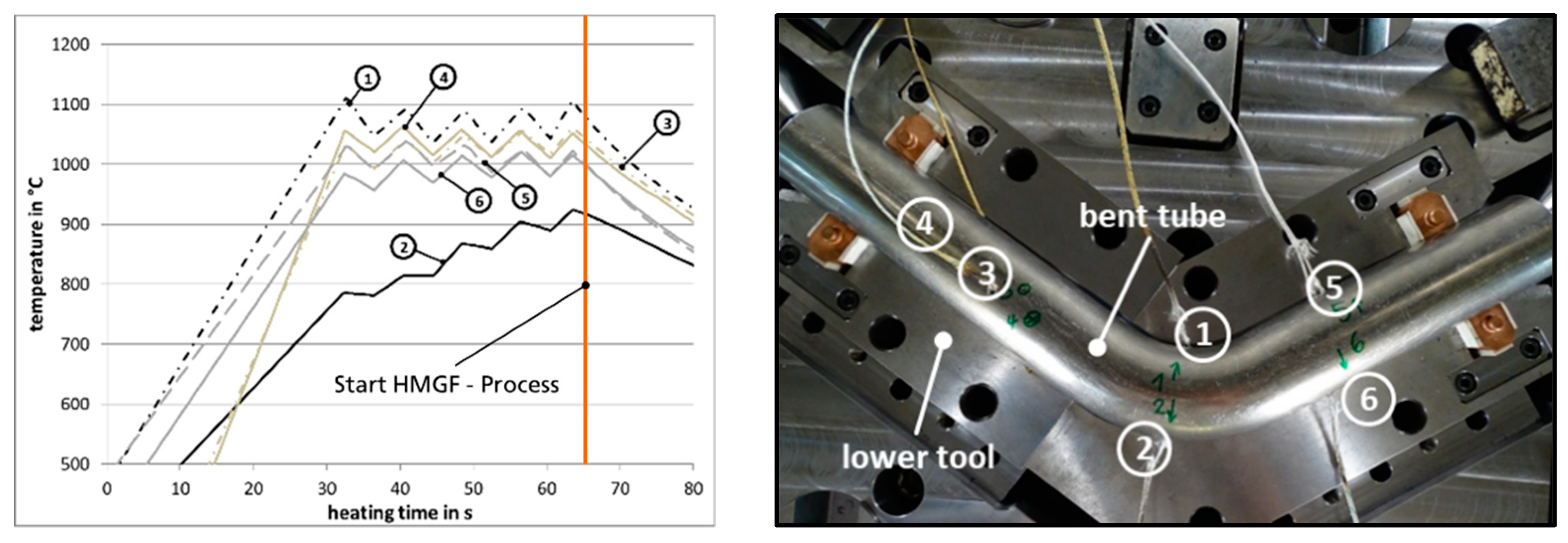
The explanation for this inhomogeneous temperature distribution is the current flow, which follows the shortest possible route through the component due to the smallest electrical resistance. Therefore, the current flow concentrates on the inner radius of the curved part. In order to counteract inhomogeneous temperature distribution and to achieve the required minimum temperature at any point, a suitable pulsed current was applied to the component. In the short time window without power supply in-between two subsequent pulses, areas that are relatively hot compared to their surroundings can dissipate warmth by heat flow into neighboring component areas, whereas regions that are relatively cool compared to their surroundings are heated by nearby hot areas. This results in the balancing of the temperature and in almost homogenous heating of the component to a targeted austenitization temperature of 911 °C. Measurement of the temperature distribution with attached thermocouples proved the suitability of this heating strategy as shown in Figure 7 without the HMGF-step. The thermal sensors 3, 4, 5 and 6 at the beginning and at the end of the pipe (top, bottom, inside and outside) are heated to similar temperature levels. The highest temperature is detected by sensor 1, which is positioned on the inner curve, i.e., directly in the area where the current flows and the resistive heat is generated. Due to the pulsing of the current, the lower temperature at the outer bend of the component (i.e., at thermal sensor 2) raises to austenitization temperature without overheating the other areas. When the thermal sensor at the inner bend (1) reaches the pre-set maximum temperature, the power supply from the conductor is automatically switched off, followed by an interruption of a few seconds. A straight orange line highlights the theoretical start of the HMGF-process after reaching Ac3-point in all part areas. The conducting system has the following four adjustable parameters for controlling the pulsing current: maximum temperature, heating or pulse time, maximum current and pause time. The temperature is measured by the two mentioned pyrometers during the heating process, see Figure 5. Due to the inhomogeneous heating of the component, it was decided to focus one pyrometer onto the inner bend and the other onto the outer bend of the component in order to control the conductor. This was to ensure that the temperature in the faster-heating inner region of the part does not exceed a pre-set maximum temperature and that the outer region reaches the set minimum temperature. Figure 6, right, shows the glowing component in the almost closed tool during the heating process. As mentioned above, the top and the bottom sections of the part are hidden by the tool. First trials at Fraunhofer IWU were carried out to determine the optimized conduction heating process with the focus on reaching the AC3 temperature at any point of the component. Several tests have additionally been done with different currents. With lower current levels compared to the maximum of 2.500 A on the equipment side, only the heating time has been extended too much or the desired temperature has not been reached. Table 2 shows the final corresponding parameters characterizing the ideal heating process.

5. Forming Tests

The first tests aimed at demonstrating the feasibility of manufacturing curved, press-hardened components with conductively heated preforms. Figure 8 exemplarily shows the finished part.
This result serves as a first verification of the simulation and proves the importance of combined numerical and experimental feasibility evaluation described in Section 2 of this paper. The darkened area between the positions of contacted electrodes (blue squares), through which the current flew, was heated up to austenitization temperature Ac3. A significantly reduced scaling on the surface is immediately noticeable due to the elimination of component transfer and the correspondingly reduced exposure of the part to atmospheric conditions. This is particularly remarkable as this part was manufactured without surface coating or protective gas. In hot forming processes, the sheet is usually protected against surface scaling by AlSi® or X-tec® coating. These are aluminium-based corrosion-protective and passivating coatings, which consist in the case of AlSi 85–95% of Aluminum and 5–11% Silicon [17], in the case of X-tec of Aluminum in a special binding matrix [18]. In the investigated case, the excellent surface quality achieved by the use of conductive component heating offers the potential of shortening the process chain and of reducing the environmental impact by avoiding aggressive chemicals. Full forming is reached with an internal pressure of 60 MPa. By using the technology of conductive heating, a constant starting temperature was guaranteed for all components manufactured.

6. Characterizing Hardness and Wall Thickness of the Component

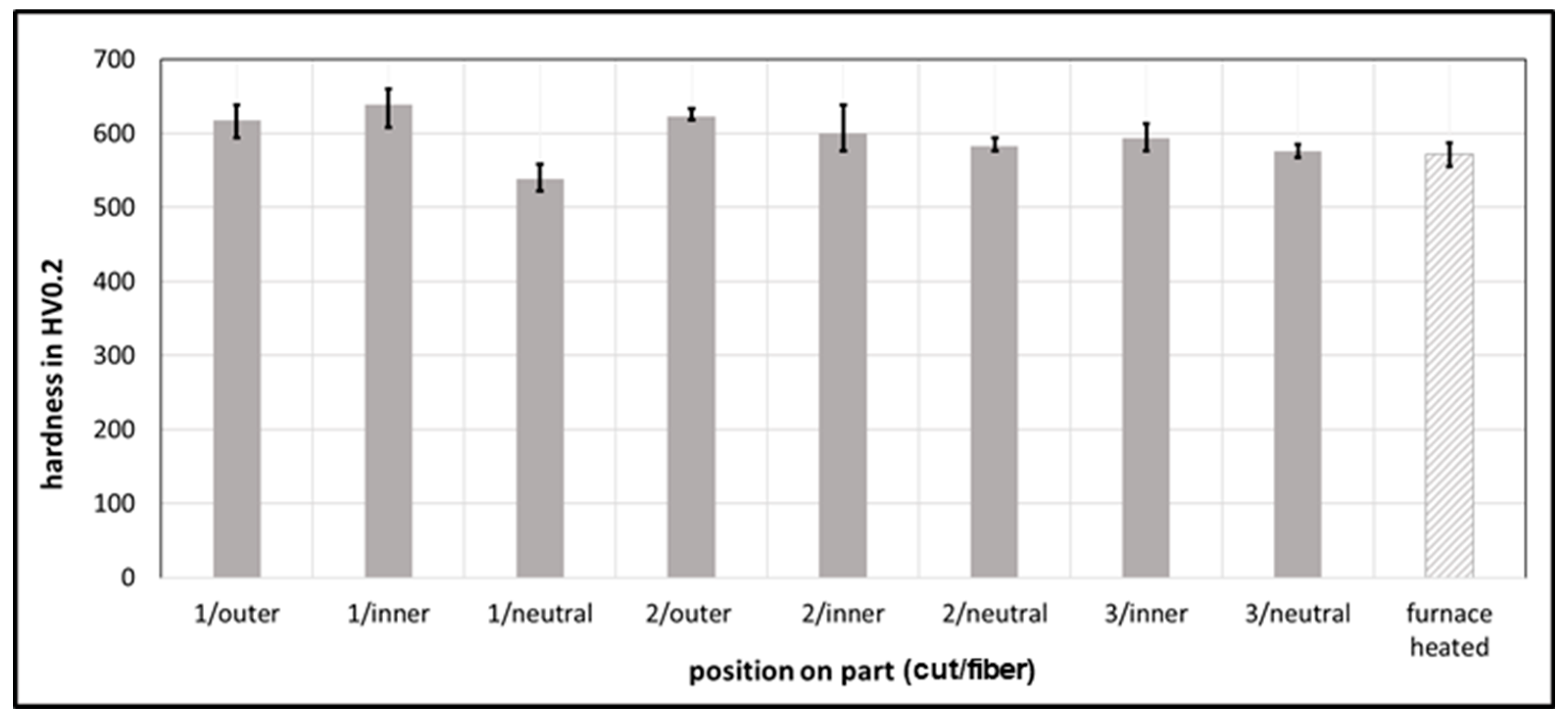
In order to evaluate the quality of the manufactured component and to provide a more detailed verification of the numerical simulation, the parts were characterized considering the distribution of hardness and wall thickness. For this purpose, exemplary components were cut at the three positions marked in Figure 8. The hardness was measured according to DIN EN ISO 6507-1:2006-03 on the outer and inner bend and on the neutral fiber on the cross-sectional area, illustrated by blue dotted lines. Figure 9 shows the results.
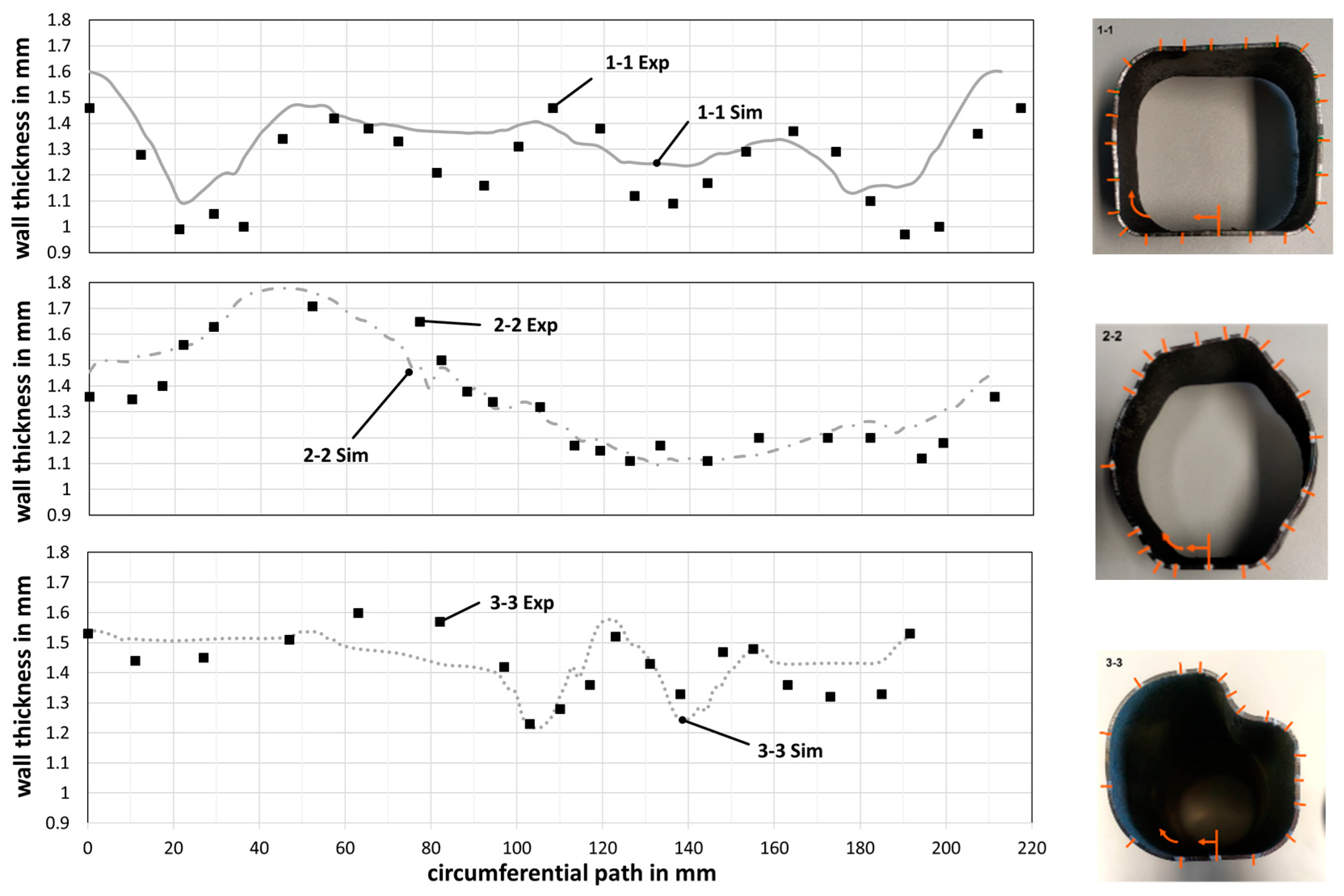
For comparison, the average hardness of a furnace-heated straight demonstrator of the same material is supplemented (striped bar in the diagram, Figure 8), compare DP3 in [11]. A minimum hardness of 540 HV was verified for all component areas. When converted according to DIN EN ISO 18,265, this value approximately corresponds to a tensile strength of 1775 MPa. This shows that the newly developed process allows for the design and heating procedure HMGF with integrated conductive component heating to be adapted to bent component geometries. Furthermore, the wall thickness of the manufactured component was measured along a circumferential path at the sections 1-1, 2-2 and 3-3 as shown in Figure 8. Figure 10 compares the result of the measurement with the simulation results. Each section is shown on the right with an initial arrow for the start of the measuring path. The curves at the different measurement positions feature different lengths since the cross-sections, and consequently, the circumferences, differ from each other. A good qualitative agreement exists between the respective simulation and real curves. In large parts, the quantitative agreement is also acceptable. Locally there are significant deviations in a range of about 30%, see for example curve 1-1, which may be caused by the inaccurate representation of the friction conditions at the high forming temperatures, which may be assumed as too low, and by the assumption regarding heat transfer. Furthermore, the results of the real tests are strongly influenced by the quality of the semi-finished product with strongly varying wall thickness in some places due to the manufacturing process.
The local thinning is suspected to be caused by the manufacturing process of the test tubes. These were produced, not as usual by roll forming, but because of their shorter dimensions by U-O-bending with prototype tools. Manufacturing deviations led to the formation of heels at radius transitions at the tool parts and thus to thinning of the raw sheet material while bent into tubes. If the material used for the pipes is established, it can be assumed that the quality will be improved in terms of wall thickness distribution.

7. Summary

Based on earlier results of tests with tool-integrated component heating, a more complex production tool was designed with integrated conduction components. A pulsed current flow was successfully tested for heating and was used for the HMGF of complex bent parts in order to guarantee the complete heating of the part to the austenitization temperature without local overheating due to the curvature of the component and due to the correspondingly inhomogeneous current distribution in the part during conductive heating. The eliminated step of transferring heated preforms into the forming tool allows for a significant reduction in component scaling and ensures the same robust condition for cooling, thus influencing the material properties such as the desired minimum hardness and overall strength of the component areas. Furthermore, the additional technological expense of the integrated conduction device for medium component quantities can be justified since additional process steps for coating are avoided and no environmentally harmful chemicals are used. Finally, the experimental verification of the simulation results was realized by examining the sheet thickness curves in three-component sections. As a result, the FEM simulation for HMGF processes on curved components can be confirmed as a reliable design tool.

Author Contributions

Conceptualization, M.B., M.W. and V.P.; methodology, M.B. and V.P.; validation, M.B., F.R. and R.D.; investigation, F.R., L.D. and M.B.; resources, L.D. and M.B.; writing—original draft preparation, M.B., L.D. and F.R.; writing—review and editing, M.B. and V.P.; visualization, M.B., L.D., F.R. and R.D.; supervision, V.P.; project administration, V.P.; funding acquisition, M.W. All authors have read and agreed to the published version of the manuscript.

Funding

The content of this paper was developed within the framework of the following publically funded project: The EU-project “Development of energy-efficient press hardening processes based on innovative sheet and tool steel alloys and thermo-mechanical process routes” with the Grant Agreement No. RFSR-CT-2015-00019 was publically funded by the European Commission, Research Fund for Coal and Steel, Technical Group TGS 7. Fraunhofer IWU would like to extend its thanks to its project partners for their cooperation and support in this project.

Conflicts of Interest

The authors declare no conflict of interest.

References

  1. Yang, Z. Overview of Global Fuel Economy Policies. In Proceedings of the 2018 APCAP Joint Forumand Clean Air Week Theme: Solutions Landscape for Clean Air, Bangkok, Thailand, 20 March 2018. [Google Scholar]
  2. Koffler, C. Automobile Produkt-Ökobilanzierung. Ph.D. Thesis, Technische Universtität Darmstadt, Darmstadt, Germany, 2007. [Google Scholar]
  3. European Commission. Communication from the Commission to the European Parliament, the Council, the European Economic and Social Committee and the Committee of the Regions. 2014. Available online: https://eur-lex.europa.eu/legal-content/EN/TXT/PDF/?uri=CELEX:52014DC0015&from=EN (accessed on 15 July 2020).
  4. Taub, A.I.; Luo, A.A. Advanced lightweight materials and manufacturing processes for automotive applications. MRS Bull. 2015, 40, 1045–1054. [Google Scholar] [CrossRef] [Green Version]
  5. Psyk, V.; Kurka, P.; Kimme, S.; Werner, M.; Landgrebe, D.; Ebert, A.; Schwarzendahl, M. Structuring by electromagnetic forming and by forming with an elastomer punch as a tool for component optimisation regarding mechanical stiffness and acoustic performance. Manuf. Rev. 2015, 2, 23. [Google Scholar] [CrossRef] [Green Version]
  6. Karbasian, H.; Tekkaya, A.E. A review on hot stamping. J. Mater. Process. Technol. 2010, 210, 2103–2118. [Google Scholar] [CrossRef]
  7. Bell, C.; Corney, J.; Zuelli, N.; Savings, D. A state of the art review of hydroforming technology. Int. J. Mater. Form. 2019, 151, 1–40. [Google Scholar] [CrossRef] [Green Version]
  8. Paul, A.; Werner, M.; Trân, R.; Landgrebe, D. Hot metal gas forming of titanium grade 2 bent tubes. In AIP Conference Proceedings; AIP Publishing LLC: Melville, NY, USA, 2017; Volume 1896, p. 050009. [Google Scholar]
  9. Paul, A.; Reuther, F.; Neumann, S.; Albert, A.; Landgrebe, D. Process simulation and experimental validation of Hot Metal Gas Forming with new press hardening steels. J. Phys. Conf. Ser. 2017, 896, 12051. [Google Scholar] [CrossRef] [Green Version]
  10. Talebi-Anaraki, A.; Chougan, M.; Loh-Mousavi, M.; Maeno, T. Hot Gas Forming of Aluminum Alloy Tubes Using Flame Heating. JMMP 2020, 4, 56. [Google Scholar] [CrossRef]
  11. Bach, M.; Degenkolb, L.; Reuther, F.; Mauermann, R.; Werner, M. Parameter measurement and conductive heating during press hardening by hot metal gas forming. In Proceedings of the 38th IDDRG Conference Enschede, Enschede, The Netherlands, 3–7 June 2019. [Google Scholar]
  12. Reuther, F.; Mosel, A.; Freytag, P.; Lambarri, J.; Degenkolb, L.; Werner, M.; Winter, S. Numerical and experimental investigations for hot metal gas forming of stainless steel X2CrTiNb18. Procedia Manuf. 2019, 27, 112–117. [Google Scholar] [CrossRef]
  13. Maeno, T.; Mori, K.-I.; Unou, C. Improvement of Die Filling by Prevention of Temperature Drop in Gas Forming of Aluminium Alloy Tube Using Air Filled into Sealed Tube and Resistance Heating. Procedia Eng. 2014, 81, 2237–2242. [Google Scholar] [CrossRef] [Green Version]
  14. N.N. Docol PHS 1800 Presshärtender Stahl: Härtbarer Borstahl Für Die Automobilindustrie. Available online: https://www.ssab.de/produkte/warenzeichen/docol/products/docol-phs-1800?accordion=downloads (accessed on 15 July 2020).
  15. Wu, Y.; Liu, G.; Wang, K.; Liu, Z.; Yuan, S. The deformation and microstructure of Ti-3Al-2.5V tubular component for non-uniform temperature hot gas forming. Int. J. Adv. Manuf. Technol. 2016, 88, 2143–2152. [Google Scholar] [CrossRef]
  16. Shapiro, B. Using LS-Dyna for Hot Stamping; Dynamore, G.H., Ed.; LSTC: Livermore, CA, USA, 2009. [Google Scholar]
  17. NANO-X GmbH. AlSi Coat 4001: Product Information. Available online: www.nano-x.de (accessed on 15 July 2020).
  18. NANO-X GmbH. Verarbeitungsvorschrift X-Tec. Available online: www.nano-x.de (accessed on 15 July 2020).
Figure 1. Demonstrator geometry.
Metals 10 01104 g001
Figure 2. Forming via pressure curve in the Hot Metal Gas Forming (HMGF) process.
Metals 10 01104 g002
Figure 3. Numerically determined wall thickness distribution.
Metals 10 01104 g003
Figure 4. Bottom half of HMGF forming tool, CAD with details: (a) overview, (b) form elements, (c) ejector, (d) guiding and force absorption elements.
Metals 10 01104 g004
Figure 5. Bottom half of HMGF forming tool, experimental setup.
Metals 10 01104 g005
Figure 6. View of thermal camera after 30 s (l) and 50 s heating time (m), real heated component (r).
Metals 10 01104 g006
Figure 7. Heating curves during pulsing current; the numbers 1–6 indicate the positions of the thermal sensors.
Metals 10 01104 g007
Figure 8. Component formed by HMGF and position of cuts.
Metals 10 01104 g008
Figure 9. Comparison of hardness: part after conduction heating or furnace heating.
Metals 10 01104 g009
Figure 10. Wall thickness validation for the three sections, experiment (Exp) and simulation (Sim).
Metals 10 01104 g010
Table 1. Chemical compound of Docol PHS 1800 by SSAB.
C (%)Si (%)Mn (%)P (max%)S (max%)Cr (max%)B (%)
0.27–0.330.15–0.351.00–1.450.0250.0100.350.0008–0.0050
Table 2. Times and temperatures for optimized component heating.
Target TemperaturePulsed Current AmplitudeHeating TimeMaximum TemperaturePause TimeNo. of CyclesTotal Heating Time
980 °C2.500 A5 s1070 °C3 s535 s