Article

A Sustainable Approach for Cadmium Recovery from Oxide Using Molten Salt Slag

1
Institute of Physics, University of Latvia, 32 Miera str., LV-2169 Salaspils, Latvia
2
Faculty of Civil Engineering, Riga Technical University, 21/1 Azenes str., LV-1048 Riga, Latvia
3
Institute of Inorganic Chemistry, Riga Technical University, P. Valdena, 3/7, LV-1048 Riga, Latvia
4
Faculty of Electrical and Environmental Engineering, Riga Technical University, 21/1 Azenes str., LV-1048 Riga, Latvia
5
Rudolfs Cimdins Riga Biomaterials Innovations and Development Centre of RTU, Institute of General Chemical Engineering, Faculty of Materials Science and Applied Chemistry, Riga Technical University, 3 Pulka Str., LV-1007 Riga, Latvia
6
Maritime Transport department, Latvian Maritime Academy, 12, k–1, Flotes Srt., LV-1016 Riga, Latvia
*
Author to whom correspondence should be addressed.
Metals 2020, 10(7), 981; https://doi.org/10.3390/met10070981
Submission received: 8 June 2020 / Revised: 7 July 2020 / Accepted: 18 July 2020 / Published: 21 July 2020
(This article belongs to the Special Issue Metal Removal and Recycling)

Abstract

:
Alkaline nickel-cadmium batteries are among the most used industrial high-power sources. Despite stricter environmental requirements, nickel-cadmium batteries still remain as the main choice for highly reliable power sources for heavy-loaded equipment. Therefore, recovery of cadmium (Cd) from spent batteries is a challenge for the modern recycling industry, particularly as it displays high bio-toxicity. The present study describes a new green approach for Cd recovery from cadmium oxide (CdO). The paper discusses using a ternary chloride composition consisting of calcium, potassium and sodium chloride, thereby avoiding the release of Cd vapour from the reaction volume during the reduction reaction from CdO. For the protective slag layer during the reduction process (which occurs at 650 °C), a 0.515:0.0796:0.405 molar ratio of CaCl2:KCl:NaCl was chosen, with the aim of achieving a melting point at 483 °C. To describe phase and elemental composition of obtained products X-ray diffraction analysis and energy dispersive X-ray spectroscopy, respectively, were applied. Electron and optical microscopy were used for morphological observations. The presence of the metallic Cd was noted. During the reduction reaction, it was noted that slag separated into two parts: a protective upper layer and bottom layer. It was also noted that metallic Cd accumulated with increasing reaction time in the bottom part of the slag.

Graphical Abstract

1. Introduction

Alkaline nickel-cadmium (Ni-Cd) batteries are widely used as autonomous sources of industrial and household current (power banks) due to a successful combination of technical, economic and electrical characteristics [1]. In recent decades, the market for secondary current sources for portable equipment has undergone significant changes, which has led to an intensive replacement of Ni-Cd batteries with lithium-ion (Li-ion) and nickel-metal-hydride (Ni-MH). Ni-Cd batteries have a relatively low energy density (45–80 W·kg−1) compared to Ni-MH (60–120 W·kg−1) and Li-ion (110–160 W·kg−1) batteries, however they offer the advantage of providing a long service life. The number of charge/discharge cycles until capacity is reduced by 80% is 1500 for Ni-Cd batteries, which is higher than that for Ni-MH (300–500) and Li-ion (500–1000) batteries. In addition, Ni-Cd batteries offer a long storage life, the ability work stably at low temperatures (up to −40 °C) and the absence of the possibility of ignition at depressurisation in comparison to Li-ion batteries, as well as lower internal resistance compared to NiMH batteries (100–200 mOhm compared to 200–300 mOhm in 6 V batteries). Therefore, Ni-Cd batteries still hold a significant position in the market among secondary industrial current sources [2].
Economic and environmental requirements and regulations are currently promoting the development of efficient and inexpensive methods for recovering precious metals from secondary sources. The utilisation and recycling of spent batteries is a rapidly growing part of the urban mining industry [3]. It has been estimated that the extraction of cadmium and nickel from spent Ni-Cd batteries requires up to 46 and 75% less energy, respectively, compared to primary production of these metals [4]. However, due to the toxicity of cadmium and its compounds, the recycling of Ni-Cd batteries is considered one of the least environmentally friendly processes [5]. Therefore, the development of methods for the disposal of Ni-Cd batteries is important from environmental, scientific and economic points of view.
The overall charge and discharge reactions in a Ni-Cd battery may be described as a cumulative reaction, as demonstrated in Equation (1) [1]:
Cd ( OH ) 2 + 2 Ni ( OH ) 2     charge   discharge   Cd   + 2 NiOOH   + 2 H 2 O
Ni-Cd cells are categorised into ventilated (open) and airtight (sealed) types of batteries. Open type batteries are commonly applied for industrial needs. The main materials of these batteries are: insulators, positive electrodes, separators, negative electrodes and a metal case. The phase composition of the components and the dimensions of the batteries can vary widely, depending on their immediate purpose. Therefore, end-of-life Ni-Cd current sources are complex, multicomponent raw materials.
In the last decade, an increased number of studies have investigated Cd extraction from spent batteries by implementing non-metallurgical approaches. These approaches include bacterially-assisted recovery [6,7], microbial metal enrichment and recovery [8] and selective separation using glycine as an eco-friendly leachant [9]. Usually, Cd nanoparticles [7] or CdS nanoparticles [9] are obtained as outputs of these Cd extraction methods. Bacterially-assisted recovery is, however, usually time-consuming, and a low-concentration of C-ions in a water-based solution are required for the realisation of this process.
Waste preparation and metallurgical processing are two main processes during the recycling of wasted batteries. Metallurgical processing can be performed in three different ways: pyrometallurgy, hydrometallurgy or hybrid processes that combine pyro- and hydro-metallurgy techniques for the production of metals or their compounds [5]. The modern pyrometallurgical approach for the extraction of Cd from Ni-Cd batteries is based on a distillation process under a high applied environmental temperature [10,11,12,13,14,15,16].
A previously developed technological solution (Inmetco, USA) included the production of Cd in a gaseous system, together with zinc and lead, with subsequent separation processing. Since 1995, the reduction of Cd in the modern plant is performed by using carbon inside a high-temperature reactor and this process is followed by evaporation and condensation [15,16].
A high degree of Cd and Ni extraction from Ni-Cd batteries has been reached by a modified hydrometallurgical process scheme [3]. However, this process is characterised by a high loss of Ni due to its partial co-deposition together with iron hydroxide.
Industrial designs of sealed Ni-Cd batteries appeared in 1950 and since then, due to their high discharge efficiency and long service life, they have been widely used [17]. However, environmentally friendly and cost-effective technology that would allow the recycling of expired batteries to produce products of adequate quality does not exist to date. Therefore, it could be concluded that studies conducted in this area are still relevant.
The use of carbonaceous reducing agents such as coal-anthracite [18] and carbon black [19] have been studied in the pyrometallurgical processes, based on Cd distillation for the recycling of spent Ni-Cd batteries and for extraction of Cd from a mixture of Cd electrodes, respectively. Experiments were carried out in special equipment under a protective atmosphere and high temperatures (up to 1100 °C). Hung et al. [20] described a pyrometallurgical method of Cd recovery using limestone and cullet as separating agents. However, this method requires temperatures up to 1450 °C and a number of the products, i.e., flue gases, slag and ingot, were obtained.
The use of slag is proposed in the pyrometallurgical processes for recycling Ni-MH batteries to extract of rare earth oxides [21,22]. In this case, as a result of high-temperature processing, a Ni-Co alloy and a hetero-oxide material are obtained. Slag systems such as CaO-CaF2, CaO-SiO2-MgO and SiO2-Al2O3 are used in these processes.
Electroslag remelting (ESR) is a secondary metal refining process. As the starting material, a continuous consumable electrode of a primary metal is usually used. The most important functions of the slag in this process are acting as a heating element via Joule heating, acting as a solvent for nonmetallic inclusions, refining the metal and protecting the liquid metal from the atmosphere [23,24]. The possibility of a metallothermic reduction of titanium tetrachloride (TiCl4) by liquid magnesium in the electroslag process using a non-consumable electrode was shown by Platacis et al. [25].
The implementation of a sustainable development production approach is required to reduce the consumption of energy and reagents and to minimise or avoid Cd vaporisation.
The full cycle of the recycling process was provided by the reduction of Cd according to Volinskij et al. [19] by the cumulative reaction from 650–1100 °C (2):
2 CdO + C   2 Cd + CO 2
The oxidation of carbon into carbon monoxide (CO) and subsequent CO reaction with CdO also leads to reduction into Cd, as shown in Equations (3) and (4), respectively:
CdO + C   Cd + CO
CdO + CO   Cd + CO 2
A CdO:C molar ratio of 1:1.5 was selected during the performance of the present study, by considering that Reaction (3) proceeds completely but Reaction (4) only partially proceeds. Such exceeding quantity of carbon prevents the oxidation of the obtained Cd on the surface of the slag.
The aim of this work is to prevent Cd evaporation from the reaction volume during high-temperature CdO reduction. Using this method, it is possible to obtain preliminary separation of metallic Cd from spent batteries without extensive heating of the whole volume of mass subjected to the recycling process. It should be noted that the melting and boiling points of pure Cd are 321 and 765 °C, respectively [25]. Finally, the reduction process of CdO is performed with finely dispersed carbon (charcoal) located under a layer of inorganic salts (slag) at a moderate applied temperature in an air atmosphere. The presented development of protective slag is essential for efficient electroslag process implementation. The goal of this research is to estimate the effect of salt slag on CdO reduction efficiency. The CdO reduction process is foreseen to heat the mixture of light metal chlorides (protective slag) in the electric furnace at the initial stage.

2. Materials and Methods

2.1. Selection of Chlorides and Preparation of Slag Cover

A ternary chloride composition consisting of calcium, potassium and sodium chlorides was used to prevent Cd evaporation from the reaction volume. A CaCl2:KCl:NaCl molar ratio of 0.515:0.0796:0.405 was selected, according to the lowest eutectic melting point (483 °C) [26], as demonstrated in the ternary CaCl2-KCl-NaCl (CKN) liquidus projection diagram shown in Figure 1. This approach prevents the intensive vaporisation of the produced Cd that typically occurs at temperatures above 700 °C [25].
Chemically pure (>99.0%) mixtures of CaCl2, KCl and NaCl reagents (Sigma-Aldrich, Merck KGaA, Darmstadt, Germany) were used to create the slag cover.
Weights of all components were measured on a laboratory scale (KERN 440-35A, 0.01 g accuracy) and subsequently milled using a kitchen grinder (Clatronic KM 3350 Kitchen Machine, Clatronic International GmbH, Kempen Germany) equipped with a plastic vessel for 3 min. The total weight of the mixture added to the grinder was 100 g for each grinding process.

2.2. Preparation of Specimens for Experiments

CdO with purity >99% (Sigma-Aldrich, Merck KGaA, Darmstadt, Germany) and particle sizes, d90, of 5–20 µm was used as the source of Cd. Carbon (C) with purity >99% (Sigma-Aldrich, Merck KGaA, Darmstadt, Germany) and particle sizes, d90, of 1–10 µm was used as the reduction agent. CdO and C were mixed in a molar ratio of 1:1.5 in isopropanol media (the mass ratio of the powder and isopropanol was 1:1.5) by using a kitchen grinder (Clatronic KM 3350) set at maximum rotation speed. The duration of grinding was 3 min. The applied volume of the mixture was about 30% of the grinder’s working volume for each grinding test.
The obtained mixture was sedimented in a glass beaker, the red isopropanol was decanted and the CdO-C slurry was dried out under ambient conditions for 24 h. The final drying was performed in the oven at 105 °C for 5 h. The obtained dried mixture of CdO–C with a weight of 8 ± 0.01 g was inserted into an alumina crucible and manually compressed (Figure 2a). Subsequently, the mixture of CKN with a weight of 13.5 ± 0.02 g was manually added and compressed to form a flat surface (Figure 2b). The obtained CdO–C mixture and CKN slag were heated from 20 to 650 °C at an applied heating rate of 100 °C·h−1. Dwell time at 650 °C was 3 and 6 h, designated as sample series CD3 and CD6, respectively. After natural cooling (cooling to room temperature in the furnace), the specimens were subjected to extraction of the reaction products. Four experiments were conducted for each (3 and 6 h) dwell time.

2.3. Preparation of Samples for Studies

The individual sample parts (upper—loose and lower—dense) were removed from the crucible and leached with distilled water to remove water-soluble components. The solid phase from the resulting suspension was separated by filtration. The precipitate was washed repeatedly with hot distilled water. It was then dried at 120 °C for 3 h and rubbed manually in a mortar. A vibratory sieve shaker (Retsch AS 200 digit, Retsch GmbH, Haan, Germany) equipped with sieves with mesh sizes 1.0, 0.1 and 0.071 mm were used for fractionation of the prepared powder.

2.4. X-ray Powder Diffraction and Microscopic Studies

X-ray powder diffraction studies were performed using a PANalytical X’Pert PRO MPD diffractometer equipped with an X’Celerator linear detector, using Cu-Kα1 radiation (λ = 1.5406 Å), 40 kV voltage and a 30 mA current. The diffraction patterns were recorded between 20° and 70° (2θ) with an angular scan step interval of 0.0334° and scanning speed of 2°·min−1.
Surface morphology and chemical composition were investigated using a field emission scanning electron microscope (SEM, Tescan Mira/LMU, TESCAN GmbH, Dortmund, Germany) equipped with an X-ray energy-dispersive spectrometer (EDX, Inca Energy 350, TESCAN GmbH, Dortmund, Germany). For optical imaging, an optical microscope (VHX-2000, Keyence Corporation, Osaka, Japan) with lenses VH-Z20R/W was used.

3. Results and Discussion

Before the thermal treatment, the CdO–C mixture was investigated for mixing homogeneity. Figure 3 shows the mixture, where dark-reddish particles correspond to CdO and black particles correspond to C. It is clearly seen that no CdO or C agglomerates were observed and the dark-reddish and black area sizes corresponded to the initial CdO and C particle sizes, respectively.

Morphology, Microscopy Investigation

After thermal treatment for 3 and 6 h, two scenarios of slag crust appearance are clearly noted in both cases, as shown in Figure 4. In 3 out of 8 cases, a mostly non-contaminated crystallised slag crust was noted (Figure 4a). In the remaining 5 cases, a dark-reddish, solid, irregular crust was noted (Figure 4b,c). As shown in Figure 4, slag cover was typical for both 3 and 6 h dwelling times. Upon breaking the slag crust, the following was noted in both cases: the cover thickness was 1.5–3 mm; the cover was intact and completely separate reaction mass from the atmosphere; some gap was seen between the cover and reaction mass (Figure 4c); the reaction mass was black in colour; and a solid yellowish or brownish mass was present at the bottom of crucible.
For the analyses, upper (loose) and lower (dense) parts of specimens were analysed separately according to the procedure described in the materials and methods sections.
In Figure 5 representative images of samples from the 6 h (CD6) experiment are shown after fractionation: loose, weakly agglomerated black powder (C) with brown inclusions (CdO) from the upper part of the sample (Figure 5a); and dense particles of irregular grey shape, beige coloured and spherical metal particles from the lower part of the sample (Figure 5b,c). Moreover, sample CD6-6 (Table 1) consisted of only spherical metal particles with a diameter of ~0.1–2 mm (Figure 5c). According to the results of SEM and EDX analysis (Figure 6), Cd was the main element of the studied material. Figure 6a,c demonstrates metal surfaces without any additional cleaning before measurements, hence the presence of elements such as K, Ca and Cl (residual amounts of slag components KCl and CaCl2) was established (Table 2, spectrums 1–3). After cleaning the surface of the metal particle using sand paper (Figure 6b), the Cd content increased up to 92.61 wt% (Table 2, spectrum 4). As shown by Müller et al. [21], the best separation efficiency of slag and metal ingot can be achieved by selecting the appropriate slag composition.
In the elemental composition of the sample, oxygen was also detected (Table 2, spectrums 1–4), which was probably mainly a part of CdO. Based on the foregoing, it can be assumed that small Cd particles encapsulated in slag (covered with a dense layer of salts) may also have been present in sample CD6-5. A comparison of the images shown in Figure 3 and Figure 5a allows for comparison of the initial reaction mixture and the mixture after the process was completed.
In the case of a reduced experiment duration to 3 h (experiment CD3), part of the material consisting of small spherical particles of metal and powder was also isolated after fractionation (Table 1, CD3-6). Figure 7 shows the SEM micrograph and EDX spectrum of this sample. The presence of cadmium was confirmed by the results of EDX analysis (Table 3). A significant amount of impurity elements was explained by the presence of a powder that could not be completely separated from the metal during fractionation in the sample. Thus, the presented results show that an increase in the experiment duration time from 3 to 6 h leads to fusion of small metal particles.
According to the XRD analysis results (Figure 8), the CdO crystalline phase was present in all powder samples CD6-1–CD6-5 (diffraction peaks at 2θ°: 33.002°, 38.286°, 55.260°, 65.919° and 69.290°, PDF 00-005-0640). In addition, the presence of mixed calcium cadmium oxide Ca0.2Cd0.8 O (PDF 00-060-0833) and small amounts of cadmium chloride hydroxide Cd4Cl3(OH)5 (PDF 00-003-0585) were also found. The impurity phase of cadmium hydroxide chloride Cd(OH)Cl (PDF 01-070-5799) was only detected in samples from the lower part of the specimen (Figure 8, curves 4 and 5). These results indicate that during the experiments, adverse reactions involving CdO and slag take place, which inevitably leads to a decrease in the efficiency of the recovery process. One of the main requirements for slag in the process under study is its lack of interaction with the initial and final components of the reaction at operating temperature. XRD analysis of a ~2 mm squashed (former spherical) particle from sample CD6-6 (Figure 8, curve 6) confirmed the presence of metallic Cd (PDF 00-005-0674), which was consistent with the EDX analysis of this sample (Figure 6, Table 2). The detection of the metal phase in samples CD1–CD5 was impossible due to the overlapping of the diffraction peaks of the components present in the water-insoluble residue.
Thus, the results of XRD analysis and SEM showed that the reduced metal was located mainly in the lower part of the specimens, as shown in Figure 9b, where CKN-salt slag is represented by yellow, CdO-C mixture by grey and formed Cd by red.
In order to increase the efficiency of the recovery process, it is planned over the course of further studies to optimise process parameters such as amount and slag composition, the molar ratio between initial reaction components, temperature and duration of the experiments, slag composition and the reaction product yield.

4. Conclusions

Use of CaCl2-KCl-NaCl eutectics as a slag protective cover for Cd reduction from CdO by powder-like carbon was proven possible by laboratory-scale experiments. Increasing the reaction time from 3 to 6 h lead to a metal particle size increase: from 0.25–0.5 mm up to several millimetres.
The results of X-ray diffraction and microscopic (electron and visible light microscopy) studies showed the possibility of undergoing the reaction of CdO reduction to metal by C under a layer of salt slag. However, in the framework of the studies, only a partial reduction of CdO to metal was observed. Therefore, a continuation of this research is planned to determine the parameters of this process that ensure the complete reduction of CdO by C.

Author Contributions

Conceptualisation was done by E.B. and A.S.; methodology development and experiment conduction was by E.B., V.S. and A.S.; analysis was by A.S. and M.M.; investigation was by V.S., E.P., M.M. and A.B.; data curation was by E.P., M.M. and A.B.; writing (original draft preparation) was by E.B., V.S. and A.S.; writing (review and editing) was by A.S. and A.B.; visualisation was by A.S. and V.S.; supervision was by E.P.; project administration was by A.B. All authors have read and agreed to the published version of the manuscript.

Funding

This research was funded by the Latvian Council of Science, project No. lzp-2018/1-0415, project name “Investigation of the method for recycling cadmium containing industrial batteries and small consumer cells through electroslag remelting for recovery of metallics in an environmentally sound manner”.

Conflicts of Interest

The authors declare no conflict of interest.

References

  1. Dasoyan, M.; Novoderezhkin, V.V.; Tomashevsky, B.E. Production of Electric Batteries; Vysshya Shkola: Moscow, Russia, 1977. (In Russian) [Google Scholar]
  2. Hrustalev, D.A. Accomulators; Izumrud: Moscow, Russia, 2003. (In Russian) [Google Scholar]
  3. Rudnik, E.; Nikiel, M. Hydrometallurgical recovery of cadmium and nickel from spent Ni–Cd batteries. Hydrometallurgy 2007, 89, 61–71. [Google Scholar] [CrossRef]
  4. Rydh, C.J.; Karlström, M. Life cycle inventory of recycling portable nickel–cadmium batteries. Resour. Conserv. Recycl. 2002, 34, 289–309. [Google Scholar] [CrossRef]
  5. Bernardes, A.M.; Espinosa, D.C.R.; Tenório, J.A.S. Recycling of batteries: A review of current processes and technologies. J. Power Sources 2004, 130, 291–298. [Google Scholar] [CrossRef]
  6. Zhou, W.; Liu, D.; Zhang, H.; Kong, W.; Zhang, Y. Bioremoval and recovery of Cd(II) by Pseudoalteromonas sp. SCSE709-6: Comparative study on growing and grown cells. Bioresour. Technol. 2014, 165, 145–151. [Google Scholar] [CrossRef] [PubMed]
  7. Paul, S.; Shakya, A.K.; Ghosh, P.K. Bacterially-assisted recovery of cadmium and nickel as their metal sulfide nanoparticles from spent Ni–Cd battery via hydrometallurgical route. J. Environ. Manag. 2020, 261, 110113. [Google Scholar] [CrossRef] [PubMed]
  8. Jiang, Q.; Song, X.; Liu, J.; Shao, Y.; He, W.; Feng, Y. In-situ enrichment and removal of Cu(II) and Cd(II) from low-strength wastewater by a novel microbial metals enrichment and recovery cell (MMERC). J. Power Sources 2020, 451, 227627. [Google Scholar] [CrossRef]
  9. Oghabi, H.; Haghshenas, D.F.; Firoozi, S. Selective separation of Cd from spent Ni-Cd battery using glycine as an eco-friendly leachant and its recovery as CdS nanoparticles. Sep. Purif. Technol. 2020, 242, 116832. [Google Scholar] [CrossRef]
  10. Espinosa, D.C.R.; Mansur, M.B. Recycling batteries. In Waste Electrical and Electronic Equipment (WEEE) Handbook; Elsevier: Amsterdam, The Netherlands, 2019; pp. 371–391. [Google Scholar]
  11. Espinosa, D.C.R.; Tenório, J.A.S. Fundamental aspects of recycling of nickel–cadmium batteries through vacuum distillation. J. Power Sources 2004, 135, 320–326. [Google Scholar] [CrossRef]
  12. Espinosa, D.C.R.; Tenório, J.A.S. Recycling of nickel–cadmium batteries using coal as reducing agent. J. Power Sources 2006, 157, 600–604. [Google Scholar] [CrossRef]
  13. Huang, K.; Li, J.; Xu, Z. Characterization and recycling of cadmium from waste nickel–cadmium batteries. Waste Manag. 2010, 30, 2292–2298. [Google Scholar] [CrossRef] [PubMed]
  14. Cox, A.; Fray, D.J. Recycling of cadmium from domestic, sealed NiCd battery waste by use of chlorination. Trans. Inst. Min. Metall. Sect. C Miner. Process. Extr. Metall. 1999, 108, C153–C158. [Google Scholar]
  15. Assefi, M.; Maroufi, S.; Yamauchi, Y.; Sahajwalla, V. Pyrometallurgical recycling of Li-ion, Ni–Cd and Ni–MH batteries: A minireview. Curr. Opin. Green Sustain. Chem. 2020, 24, 26–31. [Google Scholar] [CrossRef]
  16. Liotta, J.J.; Onuska, J.C.; Hanewald, R.H. Nickel-Cadmium Battery Recycling through the INMETCO High Temperature Metals Recovery Process; Institute of Electrical and Electronics Engineers, Inc.: Piscataway, NJ, USA, 1995. [Google Scholar]
  17. Espinosa, D.C.R.; Bernardes, A.M.; Tenório, J.A.S. An overview on the current processes for the recycling of batteries. J. Power Sources 2004, 135, 311–319. [Google Scholar] [CrossRef]
  18. Varipajev, V.N.; Daosan, M.A.; Nikolskij, V.A. The Chemical Sources of the Current; Vysshya Shkola: Moscow, Russia, 1990. [Google Scholar]
  19. Hung, Y.Y.; Yin, L.T.; Wang, J.W.; Wang, C.T.; Tsai, C.H.; Kuo, Y.M. Recycling of spent nickel–cadmium battery using a thermal separation process. Environ. Prog. Sustain. Energy 2018, 37, 645–654. [Google Scholar] [CrossRef]
  20. Müller, T.; Friedrich, B. Development of a recycling process for nickel-metal hydride batteries. J. Power Sources 2006, 158, 1498–1509. [Google Scholar] [CrossRef]
  21. Jiang, Y.; Deng, Y.; Bu, W. Pyrometallurgical extraction of valuable elements in ni-metal hydride battery electrode materials. Metall. Mater. Trans. B 2015, 46, 2153–2157. [Google Scholar] [CrossRef]
  22. Hoyle, G. Electroslag Processes: Principles and Practice; Applied Science Publishers: London, UK, 1983; ISBN -85334-164-8. [Google Scholar]
  23. Platacis, E.; Kaldre, I.; Blumbergs, E.; Goldšteins, L.; Serga, V. Titanium production by magnesium thermal reduction in the electroslag process. Sci. Rep. 2019, 9, 17566. [Google Scholar] [CrossRef] [PubMed] [Green Version]
  24. Volinskij, V.V. Methods for processing electrodes of nickel-cadmium batteries. Bull. Saratov State Tech. Univ. 2006, 3, 104–112. (In Russian) [Google Scholar]
  25. Lyon, R.N.; Katz, D.L. V Liquid-Metals Handbook; NAVEXOS P; U.S. Government Printing Office: Washington, DC, USA, 1954.
  26. FactStage CaCl2-KCl-NaCl Liquidus Projection. Available online: http://www.crct.polymtl.ca/fact/documentation/ftsalt/CaCl2-KCl-NaCl_liquidus_projection.jpg (accessed on 27 May 2020).
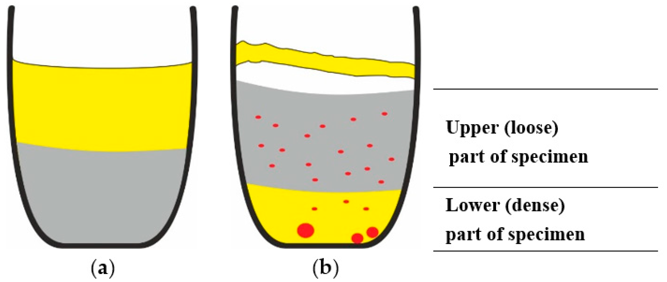
Figure 1. The ternary CaCl2-KCl-NaCl liquidus projection diagram by FactSage [26] with selected mole fractions of CaCl2, KCl and NaCl to provide the lowest eutectic melting point (483 °C).
Metals 10 00981 g001
Figure 2. Images of crucibles: (a) filled with CdO-C mixture; (b) filled with CdO-C mixture and CaCl2-KCl-NaCl (CKN), prepared for thermal treatment.
Metals 10 00981 g002
Figure 3. Optical image of homogenised CdO-C mixture at magnification 200×.
Metals 10 00981 g003
Figure 4. Images of the crucibles: (a) and (b) two typical scenarios of the CKN slag appearing after thermal treatment; (c) opened CKN slag cover.
Metals 10 00981 g004
Figure 5. Optical images of the CD6-2 (a), CD6-5 (b) and CD6-6 (c) fractions at magnifications 200×, 150× and 50×, respectively.
Metals 10 00981 g005
Figure 6. X-ray energy-dispersive spectrometer (EDX) spectrum of CD6-6 without preliminary surface cleaning—scanning areas 1–3 (a) and after surface cleaning—scanning area 4 (b) and their spectra, (c) and (d), respectively.
Metals 10 00981 g006
Figure 7. SEM micrograph (a) and EDX spectra (b) and (c) of sample CD3-6 (Table 1).
Metals 10 00981 g007
Figure 8. XRD patterns of samples: 1, initial mixture CdO + C; 2, CD6-1; 3, CD6-2; 4, CD6-4; 5, CD6-5; and 6, CD6-6.
Metals 10 00981 g008
Figure 9. Schematic images of cross sections of the crucibles: (a) filled with CdO-C mixture (grey colour) and CKN-salt slag (yellow) before the thermal treatment; (b) CdO-C mixture, Cd (red colour) and CKN-salt slag after thermal treatment.
Metals 10 00981 g009
Table 1. Description and designations of samples prepared from the experiments.
Thermal TreatmentSpecimen PartFraction Size, mmDesignationDescription
3 hUpper (loose) part of specimen<0.071CD3-1Black-brownish powder, sample weight 4.9–5.5 g
0.071–0.1CD3-2Black-brownish powder, sample weight 0.8–1.0 g
>0.1CD3-3Not detected
Lower (dense) part of specimen<0.071CD3-4Not detected
0.071–0.1CD3-5Light-grey powder, sample weight 0.6–0.8 g
>0.1CD3-6Metal-like spherical particles and light-grey powder, sample weight 0.5–0.6 g
6 hUpper (loose) part of specimen<0.071CD6-1Black-brownish powder, sample weight 5.0–5.3 g
0.071–0.1CD6-2Black-brownish powder, sample weight 0.5–0.8 g
>0.1CD6-3Not detected
Lower (dense) part of specimen<0.071CD6-4Beige powder, sample weight 0.8–1.0 g
0.071–0.1CD6-5Beige powder and metal-like particles, sample weight 0.3–0.5 g
>0.1CD6-6Metal-like spherical particles, sample weight 0.2–0.5 g
Table 2. Element composition in wt.% of sample CD6-6.
ElementOAlSiClKCaCd
Element Content in wt.%
Spectrum 119.471.61-14.351.773.2359.57
Spectrum 28.10-0.491.58-1.1288.70
Spectrum 321.330.410.616.48-2.5868.58
Spectrum 45.77-0.440.53-0.6692.61
Table 3. Element composition in wt.% of sample CD3-6.
ElementCOClKCaCd
Element Content in wt.%
Spectrum 1-17.4012.50-2.6067.50
Spectrum 2-20.3813.53-2.2263.87
Spectrum 3-39.825.220.8329.8024.33
Spectrum 416.1246.130.930.3826.889.45

