Article

Microstructural Characterization of Friction-Stir Processed Ti-6Al-4V

1
Laboratory of Mechanical Properties of Nanoscale Materials and Superalloys, Belgorod National Research University, Pobeda 85, 308015 Belgorod, Russia
2
Department of Materials Processing, Tohoku University, 6-6-02 Aramaki-aza-Aoba, Sendai 980-8579, Japan
3
Shanghai Key Laboratory of Materials Laser Processing and Modification, School of Materials Science and Engineering, Shanghai Jiao Tong University, 800 Dongchuan Road, Minhang District, Shanghai 200240, China
4
Hitachi Research Laboratory, Hitachi Ltd., 7-1-1 Omika-cho, Hitachi 319-1291, Japan
5
Air Force Research Laboratory, Materials and Manufacturing Directorate, Wright-Patterson AFB, OH 45433-7817, USA
*
Author to whom correspondence should be addressed.
Metals 2020, 10(7), 976; https://doi.org/10.3390/met10070976
Submission received: 2 July 2020 / Revised: 16 July 2020 / Accepted: 17 July 2020 / Published: 20 July 2020
(This article belongs to the Special Issue Titanium Alloys and Titanium-Based Matrix Composites)

Abstract

:
The present work was undertaken to shed additional light on the globular-α microstructure produced during FSP of Ti-6Al-4V. To this end, the electron backscatter diffraction (EBSD) technique was employed to characterize the crystallographic aspects of such microstructure. In contrast to the previous reports in the literature, neither the texture nor the misorientation distribution in the α phase were random. Although the texture was weak, it showed a clear prevalence of the P1 and C-fiber simple-shear orientations, thus providing evidence for an increased activity of the prism-<a> and pyramidal <c+a> slip systems. In addition, the misorientation distribution exhibited a crystallographic preference of 60° and 90° boundaries. This observation was attributed to a partial α→β→α phase transformation during/following high-temperature deformation and the possible activation of mechanical twinning.

1. Introduction

Ti-6Al-4V is an important structural material which is widely used in aerospace, marine, and a number of other industries. The optimal balance of service properties in this alloy is often achieved by the formation of a “globular” microstructure. To this end, the material is subjected to a complex thermo-mechanical treatment, the final step of which involves processing below the β-transus temperature (at which α + β → β). Unfortunately, conventional industrial techniques (e.g., rolling, extrusion, forging) do not impose sufficient deformation to achieve the desired fully globular microstructure. Accordingly, the development of novel techniques is necessary to improve the performance of Ti-6Al-4V. One of these approaches is friction-stir processing (FSP) [1].
FSP involves a combination of very large strains and high temperatures and thus often leads to a substantial refinement in microstructure. Because of relatively high technological requirements (e.g., tool materials, working loads, etc.,), FSP of titanium alloys is relatively difficult, and until recently, microstructural observations of FSPed Ti-6Al-4V were limited. However, rapid progress in this technology during the past few years has promoted growing interest.
The first investigations of the FSP of Ti-6Al-4V revealed a relatively narrow processing window for this technique [2,3,4,5,6,7,8,9,10,11,12,13,14,15,16,17,18]. This is believed to be due to the relatively low ductility of Ti-6Al-4V even at elevated temperatures as well as its low thermal conductivity which gives rise to considerable temperature gradients during FSP. Moreover, a significant portion of the processing window often lies above β transus. FSP in such regimes does not provide the globular microstructure thus being not practical for material processing. Another important challenge is extensive wear of the processing tool [5,9,19,20,21,22]. This effect shortens tool life (thereby increasing processing cost) and results in a substantial contamination of the processed material by tool debris. Despite these shortcomings, careful control of process parameters may provide a desirable, fully globular microstructure which consists of fine-grain (or even ultrafine-grain) α phase [6,10,23,24,25,26,27,28,29,30,31,32,33,34,35]. In such instances, the processed material exhibits excellent superplastic properties [36,37,38,39,40,41].
Until recently, relatively little attention was given to examination of the crystallographic characteristics of such microstructures. It has sometimes been reported that the texture and misorientation distribution after FSP of Ti-6Al-4V are nearly random [12,24,27,28,34,35]. Despite valuable prior efforts to describe the underlying microstructural mechanisms [42], it is still not clear whether such results are isolated cases or represent reproducible, general trends. Hence, the present work was undertaken to shed additional light on this issue. To this end, the electron backscatter diffraction (EBSD) technique was employed to characterize the globular-α microstructure produced during FSP of Ti-6Al-4V.

2. Materials and Methods

The material used in the present effort was Ti-6Al-4V, which was supplied as 7-mm-thick plate in the mill-annealed condition. Microstructural details of the base material are shown in supplementary Figures S1–S3. This material was friction-stir processed using a cobalt-based FSP tool. Based on previous experience, a relatively-low spindle (rotation) rate of 120 rpm was used to keep the processing temperature below the β transus. To investigate two points in a possible processing window, trials using feed rates of 15 and 30 mm/min were conducted. The welding tool had a diameter of 17.5 mm and a probe of 5.8 mm in length. Additional processing details were proprietary to Hitachi Ltd. To maintain consistency with the terminology in the literature, the principal directions of the process geometry are denoted herein as the welding direction (WD), transverse direction (TD), and normal direction (ND).
Microstructural observations were performed on a transverse cross-section (TD × ND plane) using optical microscopy (OM), scanning electron microscopy (SEM), electron probe microanalysis (EPMA), and EBSD. For the OM, SEM, and EPMA examinations, sectioned samples were first ground with silicon carbide abrasive papers, mechanically polished with 1-μm diamond, and then chemically etched with Kroll’s reagent (3% HNO3, 2% HF, and 95% H2O). A suitable surface finish for EBSD was obtained by mechanical polishing in a similar fashion followed by long-term (24 h) vibratory polishing with colloidal silica.
SEM and EBSD analysis were conducted using a Hitachi S-4300SE field-emission-gun SEM (FEG-SEM) (Hitachi, Tokyo, Japan) equipped with a TSL OIMTM EBSD system (EDAX, Mahwah, NJ, USA) and operated at an accelerating voltage of 25 kV. All SEM examinations were made in the secondary-electron mode. To reveal the microstructure at different length scales, EBSD maps were acquired with scan step sizes of either 0.5 or 0.2 μm. For each diffraction pattern, nine Kikuchi bands were used to minimize mis-indexing errors. To ensure reliability of the EBSD data, small grains comprising one or two pixels were automatically removed from the maps by applying the grain-dilation feature of the EBSD software. To eliminate spurious boundaries caused by orientation noise, a lower-limit boundary misorientation cut-off of 2° was employed. Furthermore, a 15° criterion was applied to differentiate low-angle boundaries (LABs) and high-angle boundaries (HABs). The grain size was quantified from the EBSD data by applying either the grain-reconstruction approach [43] (i.e., converting each grain to a circle with equivalent area and calculating the associated circle-equivalent diameter) or the conventional grain-boundary intercept method. EPMA measurements were conducted with a JEOL XM-85300FBU FEG-SEM (JEOL, Tokyo, Japan) operated at an accelerating voltage of 15 kV.

3. Results and Discussion

3.1. Preliminary Analysis

Low-magnification optical images of the FSP’ed samples (Figure 1) revealed a distinct stir zone for both feed rates. In the sample friction-stirred at the higher rate, a tunnel-type defect was found (indicated by the arrow in Figure 1b). Considering the relatively small change in process variables for the two cases, this observation suggested a rather-narrow processing window, a finding consistent with prior work [12,13,14,15,16,17,18]. To avoid the possible influence of this defect on the interpretation of microstructure evolution and material flow, subsequent examination was thus focused on the defect-free material produced using a feed rate of 15 mm/min.
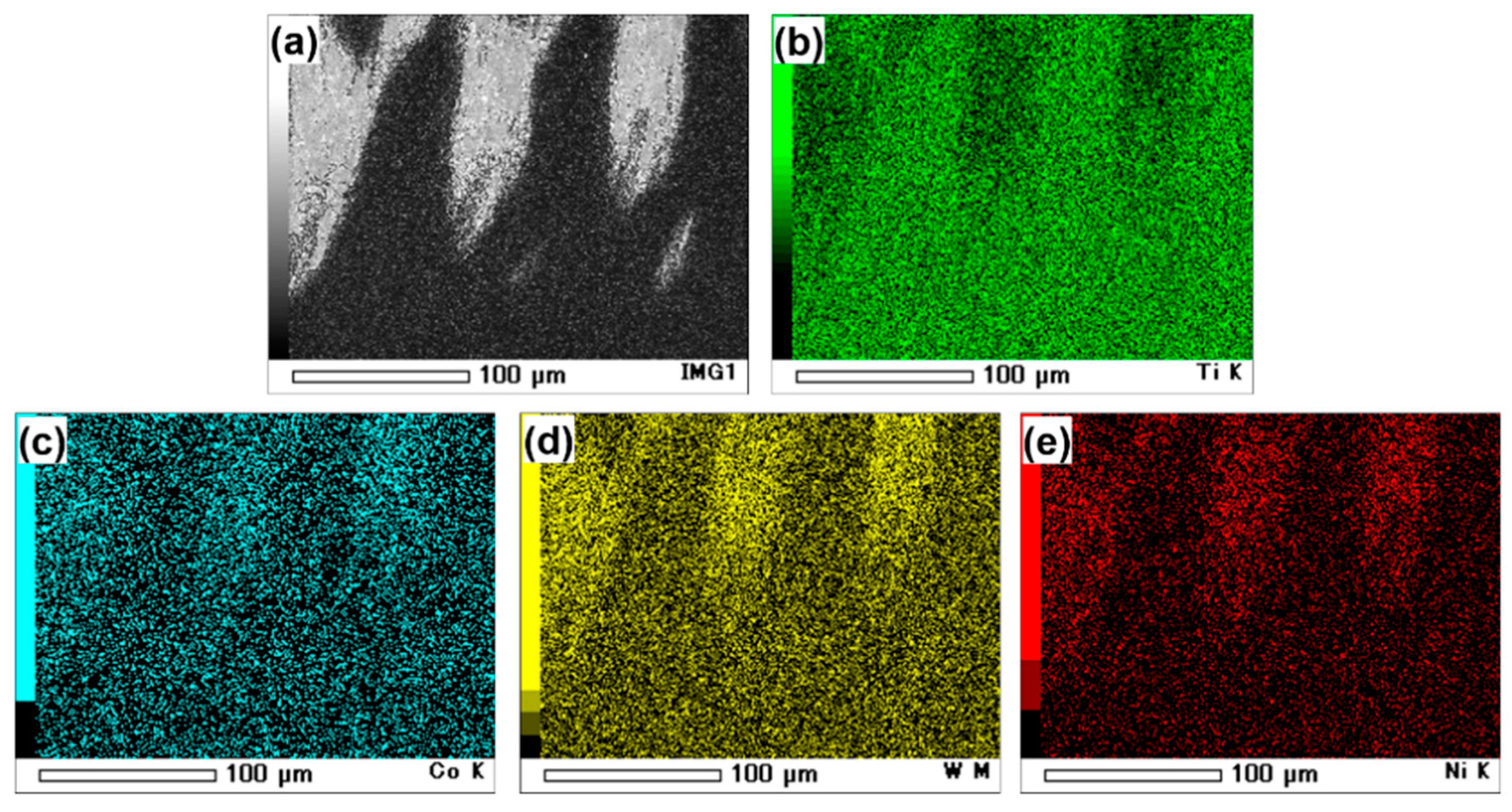
One of the most striking features of the processed material was the very specific structural pattern which evolved at the advancing side and (Figure 1), to a lesser extent, at the upper surface of the stir zone (not shown). Such structures are often observed in friction-stirred Ti-6Al-4V and are usually attributed to tool wear [9,19,20,21,22]. SEM and EPMA of the material at the advancing side revealed the origin of this macrostructure (Figure 2). In the SEM image (Figure 2a), the α phase is dark, and the β phase is light. From this micrograph, it is appeared that the lighter features were β (or a β-rich) phase. The conclusion that some regions had transformed to β was rationalized by EPMA chemical maps (Figure 2b–e). These maps did indeed indicate a relatively-low concentration of titanium (Figure 2b) and an enrichment in cobalt, tungsten, and nickel (Figure 2c–e, respectively). Each of these elements are included in the specification for the processing-tool material. Therefore, it was likely that the observed clustering of these elements in the stir zone was associated with tool wear during FSP. The appropriate binary phase diagrams (not shown) indicated that additions of these elements to titanium decrease the β transus. Accordingly, a local inter-alloying of the stir zone material by these elements should result in stabilization of the β phase, as was observed (Figure 2a). Moreover, these observations are in good agreement with prior findings [9,19,20,21,22].

3.2. Microstructure Distribution within Stir Zone

In addition to the tool wear discussed in the previous section, noticeable variations in microstructure were found in the thickness direction of the stir zone (Figure 3). As indicated by the SEM micrographs, all of the microstructures were dominated by a relatively-fine globular-α phase. This indicates that the processing temperature was indeed below the β transus. In the upper and mid-thickness sections of the stir zone, in particular, a significant amount of secondary α (αs) was also noted (Figure 3a,b). These observations suggested that the temperature in these areas likely exceeded ~900 °C, and that the material had experienced a partial α→β→αs phase transformation sequence.
As expected, the finest microstructure was observed at the stir-zone root (Figure 3c). This is consistent with previous work, and is usually explained in terms of the relatively-low thermal conductivity of titanium alloys [13,15,18,24,44,45,46] and the fact that the main source of heating during FSP is friction between the workpiece surface and tool shoulder [1]. Accordingly, the local temperature is typically believed to decrease in the downward direction, thereby enhancing the microstructure-refinement effect at the stir zone root. Nevertheless, it was surprising to find a fine grain structure in the upper region of the stir zone as well (Figure 3a). The source of this effect is less clear, but is sometimes attributed to the relatively-large strain induced by the tool shoulder during FSP. Thus, the coarsest microstructure was observed at the mid-thickness of the stir zone (Figure 3b).

3.3. Microstructure Morphology and Grain Size

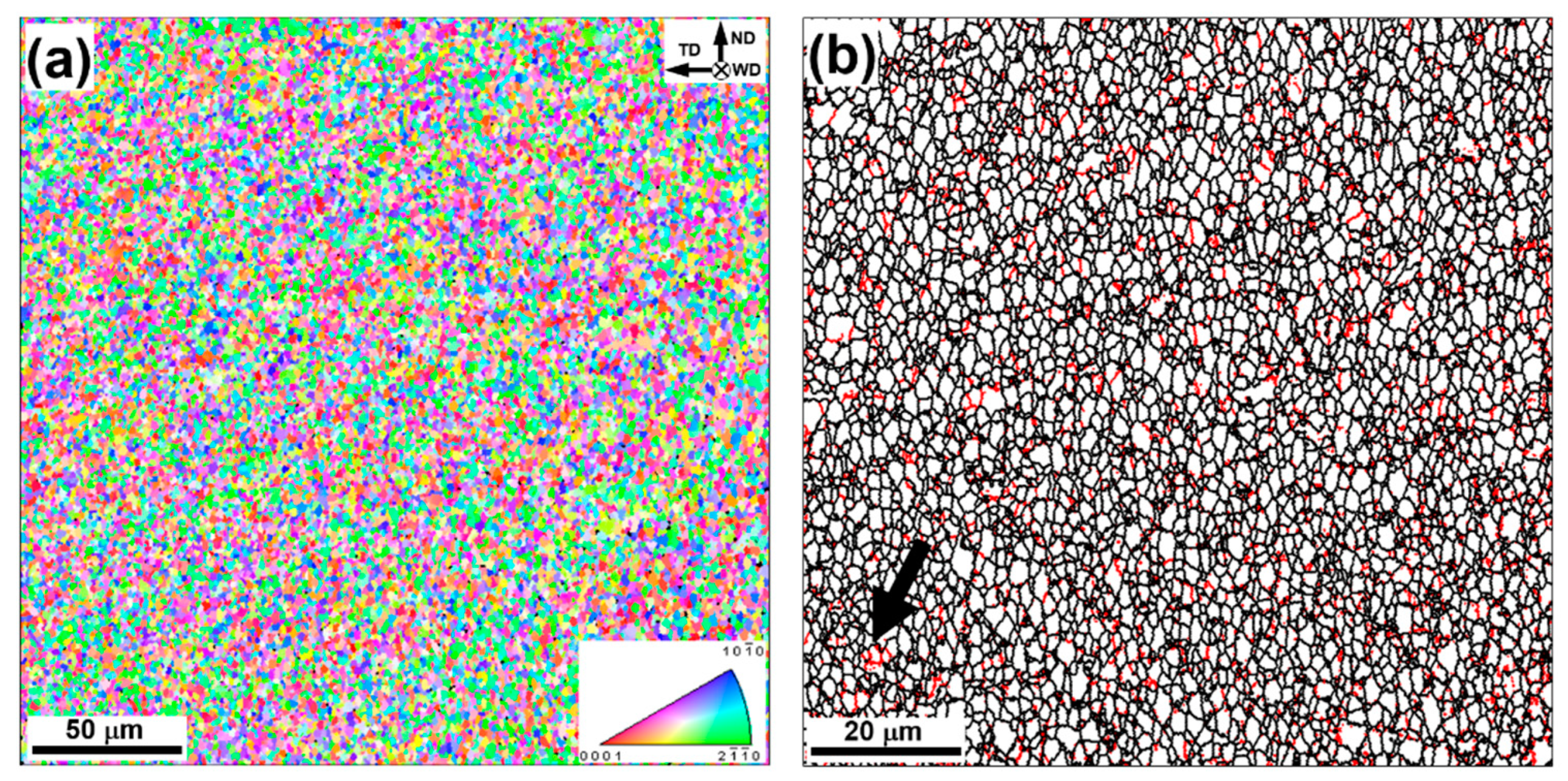
EBSD maps taken from the central section of the stir zone (Figure 4) provided deeper insight into microstructure evolution. The corresponding microstructure statistics derived from the EBSD maps are summarized in Figure 5, Figure 6 and Figure 7. Due to difficulties in indexing the β phase, however, only limited data on this microstructural constituent could be obtained. Thus, the analysis in the present investigation was focused on the α phase, and the fine β particles (Figure 3b) were neglected during the evaluation of grain size and misorientation distribution for the α phase.
The low-resolution EBSD maps (Figure 4a) showed that the microstructure was very uniform. Equally important, there was no pronounced clustering of α grains sharing a common crystallographic axis (i.e., so-called “microtexture”) in contrast to conventional processing of Ti-6Al-4V. This observation has been also highlighted by Pilchak, et al. [42]. In that work, the effect was attributed to the specific nature of deformation during FSP, which is close to simple shear and therefore has no true “end”/stable crystallographic orientation(s). The effect may also be enhanced by the relatively-complex strain path inherent to FSP in general.
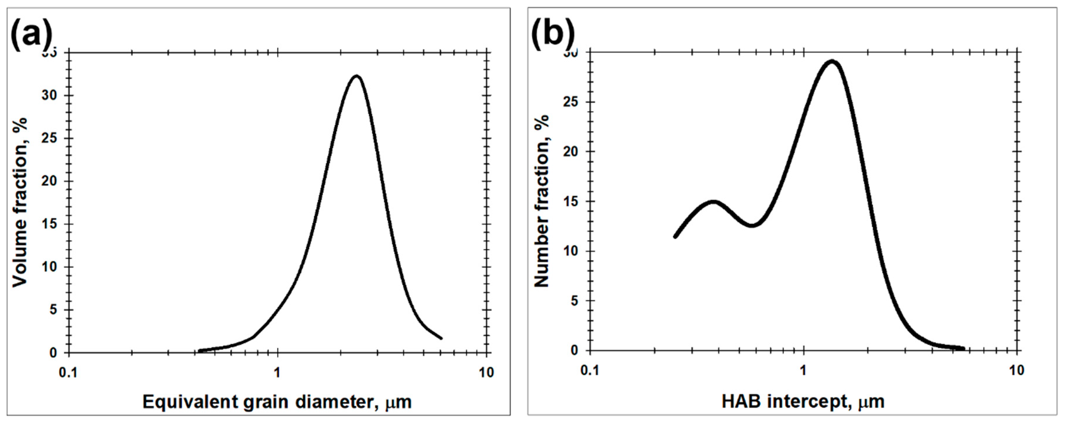
As expected, the microstructure was dominated by the fine grains (Figure 4b) with a mean circle-equivalent diameter of 1.4 μm (Figure 5a) and mean HAB intercept length of 1 μm (Figure 5b). The HAB fraction was 86%. Not surprisingly, the remnant LABs were clustered primarily within relatively-coarse α grains which tended to subdivide them into smaller-scale fragments; an example is indicated by the arrow in Figure 4b. These observations suggested that microstructure evolution within the α phase during FSP occurred by a process of continuous dynamic recrystallization (CDRX), thus being consistent with similar reports in the literature [25,35,42]. Also in agreement with previous work, the α grains exhibited a nearly-globular shape, thus confirming the formation of a globular structure (Figure 4b).

3.4. Texture

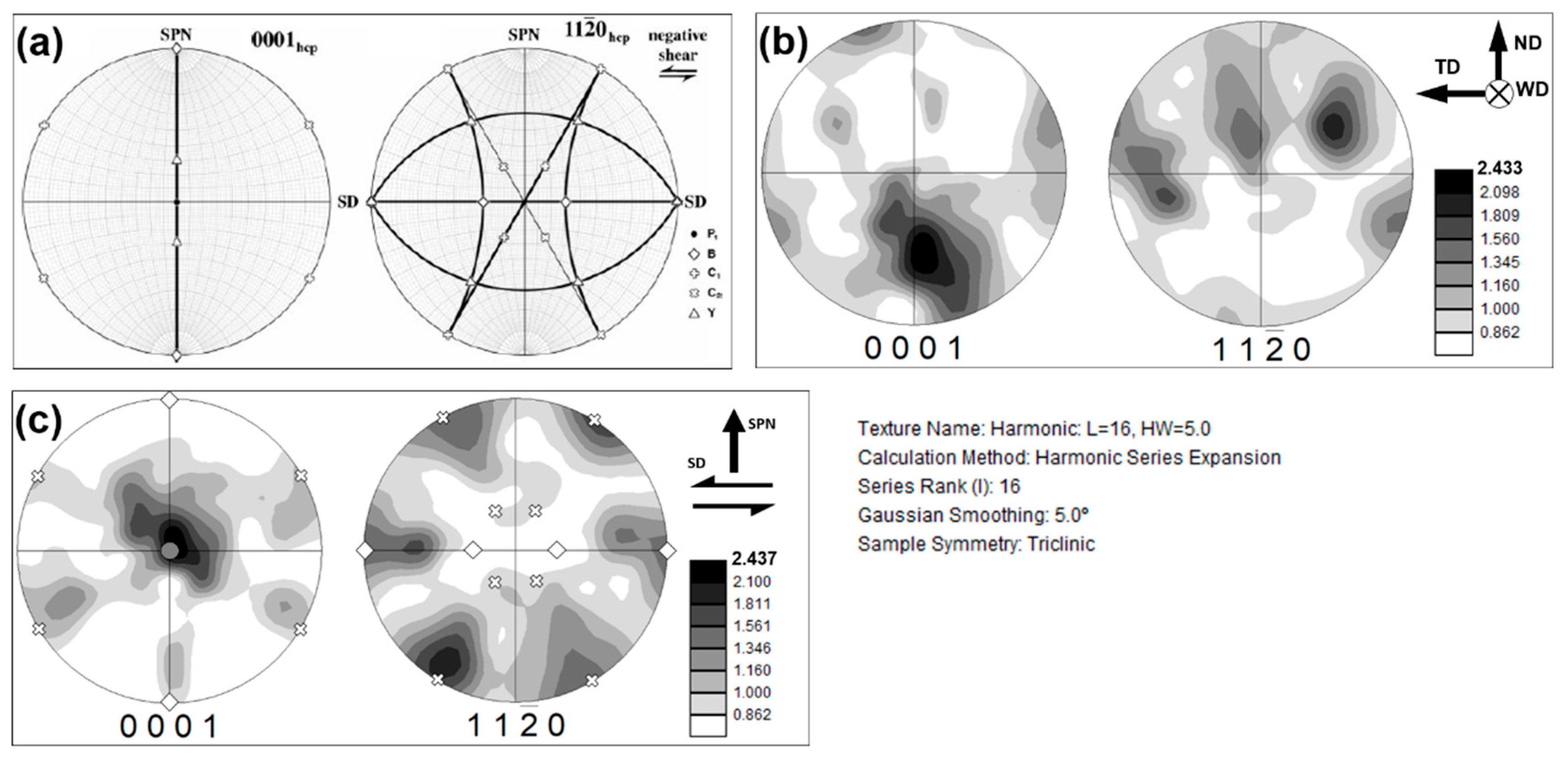
It is commonly accepted that the deformation imposed during FSP is close to a mode of simple-shear [47,48]. However, according to Pilchak et al. [42], the strain path is simple shear only at limiting points around the tool; elsewhere, it is a mixture of simple and pure shear. The ideal orientations expected during simple shear of hcp crystals (such as α titanium) are given in Figure 6a and Table 1. For FSP, the shearing direction is tangential to the tool-rotation direction [48]. However, the orientation of the shear plane is usually less evident. Often, it is thought to be tangential to the tool-workpiece interface [49] or oriented nearly-parallel to the boundary between the stir zone and the thermo-mechanically affected zone (TMAZ) as in the truncated-cone model [50].
The textures developed during FSP were interpreted in terms of { 0001 } and { 11 2 ¯ 0 } pole figures (Figure 6b) derived from the low-resolution EBSD map (Figure 4a). Assuming that the shear plane in the present work was parallel to the stir zone-TMAZ boundary, the measured pole figures were rotated 50° about the TD to align them with the presumed geometry of simple shear. They were also given an additional rotation of 15° about the ND in order to adjust the experimental data with the ideal textures. The rotated pole figures are shown in Figure 6c.
From the comparison of the rotated pole figures with the ideal textures in Figure 6a, it appeared that the FSP material was characterized by a preference for the P1 { 1 ¯ 100 } < 2 ¯ 110 > and C-fiber components. Based on literature findings (Table 1), such results implied a prevalence of prism- <a> and pyramidal- <c+a> slip during FSP. In addition, there was some evidence for the development of a B-fiber component (Figure 6c), thus implying the possible activation of basal <a> slip as well (Table 1). However, these observations were not clear-cut, and thus further verification may be helpful. While the dominance of prism slip (with its low critical resolved shear stress) was expected, the activation of the pyramidal slip appeared somewhat surprising. It was likely necessitated by strain-compatibility requirements and perhaps the presence of the β phase. Despite these observations, the measured texture was weak with a maximum peak intensity of only ~2.5 times random (Figure 6c). This observation was in the line with previous texture studies [24,27,28,34,35].
It is also worth noting that the final microstructure was produced partially by a local α→β→αs phase transformation, as mentioned in Section 3.2. This process could influence texture evolution, and thus the analysis given in the present section may be oversimplified. Therefore, orientation measurements within the prior-β phase (and associated the secondary α) are needed to provide further insight into the evolution of texture during FSP.

3.5. Misorientation Distribution

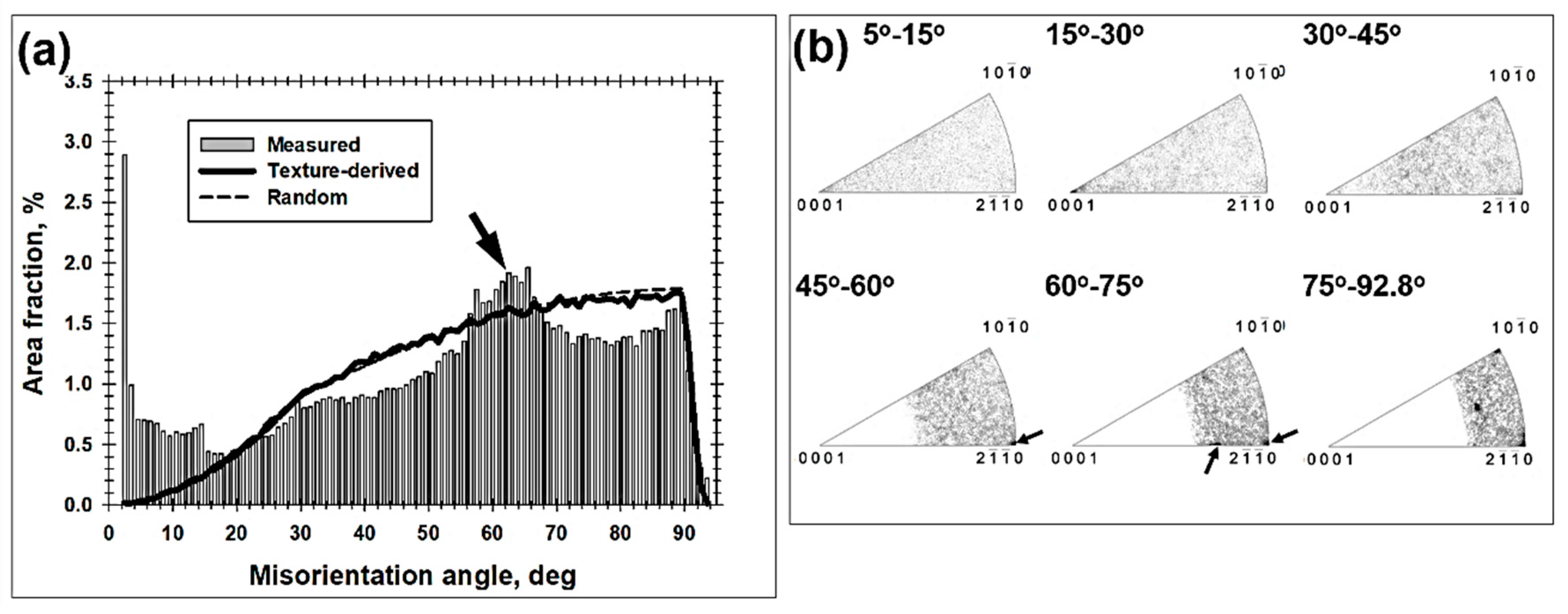
Misorientation data extracted from the high-resolution EBSD map (Figure 4b) were arranged as distributions of misorientation angles and misorientation (rotation) axes (Figure 7). To assist in the interpretation of these experimental results, a so-called uncorrelated (or texture-derived) misorientation distribution was also calculated. For this approach, 1000 pixels were arbitrarily selected from the EBSD map and all possible misorientations between them were determined using one of the standard options in the EBSD software. Results from this texture-derived distribution were broadly similar to the distribution for a texture comprising randomly oriented grains (Figure 7a). This observation was likely due to the very weak texture that was developed within the stir zone, as discussed in the previous section. On the other hand, the measured grain-boundary misorientation distribution was noticeably different from both the texture-derived and random ones. Specifically, it was characterized by a pronounced low-angle maximum, additional misorientation peaks near ~60° and ~90° (Figure 7a), and the clustering of misorientation axes around several preferred crystallographic directions (Figure 7b).
The low-angle peak was likely attributable to the very large strain experienced by the material during FSP and the continuous nature of CDRX. Surprisingly, the rotation axes of the LABs were distributed in a near-random fashion (Figure 7b). This behavior contrasted with the preferential clustering of LAB axes near the <0001> pole often observed in heavily deformed α titanium [53,54,55]. The present finding may thus be a result of the complex character of slip involving the activation of both prism- <a> and pyramidal <c+a> modes, as discussed previously.
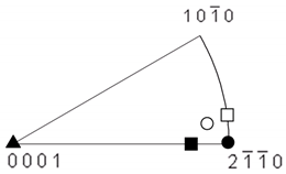
The noticeable proportion of ~60° boundaries was likely associated with the partial α→β→αs phase transformation, as discussed in Section 3.2. In titanium alloys, this transformation is normally governed by the Burgers orientation relationship, viz., { 0001 } α / / { 110 } β and < 11 2 ¯ 0 > α / / < 111 > β . Because of the crystallographic symmetry of the α and β phases, there are 12 crystallographic variants of this relationship. The possible misorientations between the variants inherited from the same prior-β grain are shown in Table 2. From the table, it is seen that 3 of 5 such variants provide a peak near 60° in the misorientation-angle distribution and a clustering of rotation axes near the < 2 1 ¯ 1 ¯ 0 > pole, in broad agreement with the experimental data (indicated by the arrows in Figure 7). This provides an explanation for the origin of the 60° peak therefore. In addition, it is worth noting that the measured fraction of “inter-variant” boundaries constituted only ~6.5% of the total grain-boundary area. The relatively low fraction of such misorientations was probably associated with very fine-grain nature of the microstructure (Figure 3b) which typically results in the nucleation of only a single α variant within some prior β grains. On the other hand, an example of the prior-β grain structure containing several secondary-α colonies (which are responsible for the inter-variant misorientations) is shown in supplementary Figure S4.
The crystallographic preference for ~90° < 2 1 ¯ 1 ¯ 0 > , ~90° < 10 1 ¯ 0 > , and ~90° < 16 ; 4 ¯ ; 12 ; ¯ 3 > misorientations (Figure 7b) is less clear. From a broad perspective, such boundaries in α titanium can be produced by mechanical twinning involving { 10 1 ¯ 2 } , { 11 2 ¯ 3 } , or { 10 1 ¯ 2 } { 11 2 ¯ 3 } modes, respectively e.g., [58]. Indeed, evidence of twinning of the α phase has been found during uniaxial compression of Ti-6Al-4V at room temperature [59] and, very recently, during the hot compression of the single-phase-α alloy Ti-7Al [60].
It should be noted that lowering the FSP temperature (and the concomitant development of ultrafine microstructures similar to that in Figure 3c) suppresses the phase transformation, but may enhance mechanical twinning. Such changes would likely result in a different misorientation distribution. On the other hand, considering the relatively narrow processing window as well as the substantial temperature gradient within the stir zone, phase transformation and twinning may always exert an influence on microstructural evolution to some degree.

4. Conclusions

The present work was undertaken to provide insight into the globular microstructure developed during FSP of Ti-6Al-4V. To this end, the advanced capabilities of the EBSD technique were employed. The main results derived from this study were as follows.
The microstructure developed in the stir zone under nominally subtransus processing conditions results from a complex superposition of several processes. In addition to the strain-induced refinement (common to FSP), it is also influenced noticeably by the partial α→β→αs phase transformation (induced by the FSP thermal cycle) and inter-alloying due to the wear of the FSP tool. The markedly inhomogeneous microstructure distribution within the stir zone shows evidence of considerable variations in thermo-mechanical conditions.
The microstructure produced in the central section of stir zone is dominated by a fully globular α phase with a mean grain size of ~1 μm and HAB fraction of 86%, and an absence of microtexture. The LAB substructure within remnant, relatively coarse α grains suggest a continuous dynamic recrystallization mechanism of α phase refinement.
Although the texture in the α phase is very weak, there is a crystallographic preference for the formation of P1 { 1 ¯ 100 } < 2 ¯ 110 > and C-fiber simple-shear components. This observation may be attributed to the dominance of prism- <a> and pyramidal <a+c> slip activity during FSP.
The misorientation distribution in the α phase is characterized by a noticeable proportion of 60° and 90° boundaries. The former boundaries are likely associated with a partial α→β→αs phase transformation, whereas the latter may indicate the possible activation of { 10 1 ¯ 2 } and/or { 11 2 ¯ 3 } twinning.

Supplementary Materials

The following are available online at https://www.mdpi.com/2075-4701/10/7/976/s1, Figure S1: SEM images of the microstructure of the base material at: (a) low magnification and (b) high magnification. Figure S2: EBSD characterization of the base material: (a) low-resolution orientation (inverse-pole-figure) map, and (b) (0001) and {11-20} pole figures showing the texture. In (a), LABs and HABs are depicted as white and black lines, respectively. Figure S3: EBSD characterization of the base material: (a) high-resolution orientation (inverse-pole-figure) map, and (b) misorientation distribution. In (a), LABs and HABs are depicted as white and black lines, respectively. In (b), the insert in the top right corner shows misorientation-axis distribution. Figure S4: SEM micrograph taken from the stir zone that exemplifies several secondary-alpha colonies within a prior-β grain.

Author Contributions

Conceptualization, S.H., Y.S.S., S.M.; methodology, S.H., Y.S.S., S.M.; formal analysis, S.M.; investigation, S.M.; resources, S.H., Y.S.S., H.K.; data curation, S.H., Y.S.S., S.M.; writing—original draft preparation, S.M.; writing—review and editing, Y.S.S., H.K., S.H., A.L.P., S.L.S.; visualization, S.M.; supervision, S.H., Y.S.S., H.K.; project administration, Y.S.S.; funding acquisition, S.H. All authors have read and agreed to the published version of the manuscript.

Funding

This research was based on results obtained from a project commissioned by the New Energy and Industrial Technology Development Organization (NEDO).

Conflicts of Interest

The authors declare no conflict of interest.

References

  1. Mishra, R.S.; Ma, Z.Y. Friction stir welding and processing. Mater. Sci. Eng. R 2005, 50, 1–78. [Google Scholar] [CrossRef]
  2. Juhas, M.C.; Viswanathan, G.B.; Fraser, H.L. Microstructural evolution in Ti alloy friction stir welds. In Proceedings of the Second Symposium on Friction Stir Welding, Gothenburg, Sweden, 26–28 June 2000. [Google Scholar]
  3. Juhas, M.C.; Viswanathan, G.B.; Fraser, H.L. Characterization of microstructural evolution in a Ti-6Al-4V friction stir weld. In Proceedings of the Lightweight Alloys for Aerospace Application, TMS, Warrendale, PA, USA, 12–14 February 2001; Jata, K., Lee, E.W., Frazier, W., Kim, N.J., Eds.; TMS: Warrendale, PA, USA, 2001; pp. 209–217. [Google Scholar]
  4. Ramirez, A.J.; Juhas, M.C. Microstructural evolution in Ti-6Al-4V friction stir welds. In Material Science Forum; Trans Tech Publications Ltd.: Zurich-Uetikon, Switzerland, 2003; Volume 426, pp. 2999–3004. [Google Scholar]
  5. Pavka, P.A. Microstructural Evolution of Friction Stir Processed Ti-6Al-4V. Ph.D. Thesis, Ohio State University, Columbus, OH, USA, 2006. [Google Scholar]
  6. Pilchak, A.L.; Juhas, M.C.; Williams, J.C. Microstructural changes due to friction stir processing of investment-cast Ti-6Al-4V. Metall. Mater. Trans. A 2007, 38, 401–408. [Google Scholar] [CrossRef]
  7. Pilchak, A.L.; Li, Z.T.; Fisher, J.J.; Reynolds, A.P.; Juhas, M.C.; Williams, J.C. The relationship between friction stir processing (FSP) parameters and microstructure in investment cast Ti-6Al-4V. In Friction Stir Welding and Processing IV; Mishra, R.S., Mahoney, M.W., Lienert, T.J., Jata, K.V., Eds.; TMS: Warrendale, PA, USA, 2007; pp. 419–427. [Google Scholar]
  8. Pilchak, A.L.; Juhas, M.C.; Williams, J.C. The effect of friction stir processing on microstructure and properties of investment cast Ti-6Al-4V. In Proceedings of the 11th World Titanium 2007 Conference, Kyoto, Japan, 3–7 June 2007; Ninomi, M., Akiyama, S., Ikeda, M., Hagiwara, M., Maruyama, K., Eds.; Japan Institute of Metals: Sendai, Japan, 2007; pp. 1723–1726. [Google Scholar]
  9. Pilchak, A.L.; Juhas, M.C.; Williams, J.C. Observations of tool-workpiece interactions during friction stir processing of Ti-6Al-4V. Metall. Mater. Trans. A 2007, 38, 435–437. [Google Scholar] [CrossRef]
  10. Pilchak, A.L.; Norfleet, D.M.; Juhas, M.C.; Williams, J.C. Friction stir processing of investment-cast Ti-6Al-4V: Microstructure and properties. Metall. Mater. Trans. A 2008, 39, 1519–1524. [Google Scholar] [CrossRef]
  11. Pilchak, A.L.; Juhas, M.C.; Williams, J.C. A comparison of friction stir processing of investment cast and mill-annealed Ti-6Al-4V. Weld. World 2008, 52, 60–68. [Google Scholar] [CrossRef]
  12. Lauro, A. Friction stir welding of titanium alloys. Weld. Int. 2012, 26, 8–21. [Google Scholar] [CrossRef]
  13. Su, J.; Wang, J.; Mishra, R.S.; Xu, R.; Baumann, J.A. Microstructure and mechanical properties of a friction stir processed Ti-6Al-4V alloy. Mater. Sci. Eng. A 2013, 573, 67–74. [Google Scholar] [CrossRef]
  14. Lippold, J.C.; Livingston, J.J. Microstructure evolution during friction stir processing and hot torsion simulation of Ti-6Al-4V. Metall. Mater. Trans. A 2013, 44, 3815–3825. [Google Scholar] [CrossRef]
  15. Edwards, P.; Ramulu, M. Identification of process parameters for friction stir welding Ti-6Al-4V. J. Eng. Mater. Technol. 2010, 132, 031006–1. [Google Scholar] [CrossRef]
  16. Edwards, P.; Ramulu, M. Effect of process conditions on superplastic forming behavior in Ti-6Al-4V friction stir welds. Sci. Technol. Weld. Join. 2009, 14, 669–680. [Google Scholar] [CrossRef]
  17. Sanders, D.G.; Ramulu, M.; Edwards, P.D.; Cantrell, A. Effect on the surface texture, superplastic forming, and fatigue performance of Titanium 6Al-4V friction stir welds. J. Mater. Eng. Perform. 2010, 19, 503–509. [Google Scholar] [CrossRef] [Green Version]
  18. Edwards, P.D.; Ramulu, M. Investigation of microstructure, surface and subsurface characteristics in titanium alloy friction stir welds of varied thicknesses. Sci. Technol. Weld. Join. 2009, 14, 476–483. [Google Scholar] [CrossRef]
  19. Wang, J.; Su, J.; Mishra, R.S.; Xu, R.; Baumann, J.A. Tool wear mechanisms in friction stir welding of Ti-6Al-4V. Wear 2014, 321, 25–32. [Google Scholar] [CrossRef]
  20. Pilchak, A.L.; Tang, W.; Sahiner, H.; Reynolds, A.P.; Williams, J.C. Microstructure evolution during friction stir welding of mill-annealed Ti-6Al-4V. Metall. Mater. Trans. A 2011, 42, 745–762. [Google Scholar] [CrossRef]
  21. Fall, A.; Fesharaki, M.H.; Khodabandeh, A.R.; Jahazi, M. Tool wear characteristics and effect on microstructure in Ti-6Al-4V friction stir welded joints. Metals 2016, 6, 275. [Google Scholar] [CrossRef] [Green Version]
  22. Wu, L.H.; Wang, D.; Xiao, B.L.; Ma, Z.Y. Tool wear and its effect on microstructure and properties of friction stir processed Ti-6Al-4V. Mater. Chem. Phys. 2014, 146, 512–522. [Google Scholar] [CrossRef]
  23. Kitamura, K.; Fujii, H.; Iwata, Y.; Sun, Y.S.; Morisada, Y. Flexible control of the microstructure and mechanical properties of friction stir welded joints. Mater. Design 2013, 46, 348–354. [Google Scholar] [CrossRef]
  24. Yoon, S.; Ueji, R.; Fujii, H. Effect of rotation rate on microstructure and texture evolution during friction stir welding of Ti-6Al-4V plates. Mater. Character. 2015, 106, 352–358. [Google Scholar] [CrossRef] [Green Version]
  25. Zhou, L.; Liu, H.J.; Liu, P.; Liu, Q.W. The stir zone microstructure and its formation mechanism in Ti-6Al-4V friction stir welds. Scripta Mater. 2009, 61, 596–599. [Google Scholar] [CrossRef]
  26. Liu, H.J.; Zhou, L.; Liu, Q.W. Microstructural characteristics and mechanical properties of friction stir welded joints of Ti-6Al-4V titanium alloy. Mater. Design 2010, 31, 1650–1655. [Google Scholar] [CrossRef]
  27. Liu, H.J.; Zhou, L. Microstructural zones and tensile characteristics of friction stir welded joint of TC4 titanium alloy. Trans. Nonferrous. Met. Soc. China 2010, 20, 1873–1878. [Google Scholar] [CrossRef]
  28. Zhou, L.; Liu, H.-J.; Wu, L.-Z. Texture of friction stir welded Ti-6Al-4V alloy. Trans. Nonferrous Met. Soc. China 2014, 24, 368–372. [Google Scholar] [CrossRef]
  29. Farnoush, H.; Bastami, A.A.; Sadeghi, A.; Mohandesi, J.A.; Moztarzadeh, F. Tribological and corrosion behavior of friction stir processed Ti-CaP nanocomposites in simulated body fluid solution. J. Mech. Beh. Biomed. Mater. 2013, 20, 90–97. [Google Scholar] [CrossRef] [PubMed]
  30. Esmaily, M.; Mortazavi, S.N.; Todehfalah, P.; Rashidi, M. Microstructural characterization and formation of α/ martensite phase in Ti-6Al-4V alloy butt joints produced by friction stir and gas tungsten arc welding processes. Mater. Design 2013, 47, 143–150. [Google Scholar] [CrossRef]
  31. Pasta, S.; Reynolds, A.P. Residual stress effects on fatigue crack growth in a Ti-6Al-4V friction stir welds. Fatigue Fract. Eng. Mater. Struct. 2008, 31, 569–580. [Google Scholar] [CrossRef]
  32. Steuwer, A.; Hattingh, D.G.; James, M.N.; Singh, U.; Buslaps, T. Residual stress, microstructure and tensile properties in Ti-6Al-4V friction stir welds. Sci. Technol. Weld. Join. 2012, 17, 525–533. [Google Scholar] [CrossRef]
  33. Muzvidziwa, M.; Okazaki, M.; Suzuki, K.; Hirano, S. Role of microstructure on the fatigue crack propagation behavior of a friction stir welded Ti-6Al-4V. Mater. Sci. Eng. A 2016, 652, 59–68. [Google Scholar] [CrossRef]
  34. Yoon, S.; Ueji, R.; Fujii, H. Microstructure and texture distribution of Ti-6Al-4V alloy joints friction stir welded below β-transus temperature. J. Mater. Process. Technol. 2016, 229, 390–397. [Google Scholar] [CrossRef] [Green Version]
  35. Ma, Z.Y.; Pilchak, A.L.; Juhas, M.C.; Williams, J.C. Microstructural refinement and property enhancement of cast light alloys via friction stir processing. Scripta Mater. 2008, 58, 361–366. [Google Scholar] [CrossRef]
  36. Zhang, W.; Liu, H.; Ding, H.; Fujii, H. Superplastic deformation mechanism of the friction stir processed fully lamellar Ti-6Al-4V alloy. Mater. Sci. Eng. A. 2020, 785, 139390. [Google Scholar] [CrossRef]
  37. Ramulu, M.; Edwards, P.D.; Sanders, D.G.; Reynolds, A.P.; Trapp, T. Tensile properties of friction stir welded and friction stir welded-superplastically formed Ti-6Al-4V butt joints. Mater. Design 2010, 31, 3056–3061. [Google Scholar] [CrossRef]
  38. Sanders, D.G.; Ramulu, M.; Edwards, P.D. Superplastic forming of friction stir welds in Titanium alloy 6Al-4V: Preliminary results. Mater. Sci. Eng. Technol. 2008, 39, 353–357. [Google Scholar] [CrossRef]
  39. Edwards, P.D.; Sanders, D.G.; Ramulu, M. Simulation of tensile behavior in friction stir welded and superplastically formed Titanium 6Al-4V alloy. J. Mater. Eng. Perform. 2010, 19, 510–514. [Google Scholar] [CrossRef]
  40. Sanders, D.G.; Ramulu, M.; Klock-McCook, E.J.; Edwards, P.D.; Reynolds, A.P.; Trapp, T. Characterization of superplastically formed friction stir weld in titanium 6Al-4V: Preliminary results. J. Mater. Eng. Perform. 2008, 17, 187–192. [Google Scholar] [CrossRef]
  41. Edwards, P.D.; Sanders, D.G.; Ramulu, M.; Grant, G.; Trapp, T.; Comley, P. Thinning behavior simulations in superplastic forming of friction stir processed titanium 6Al-4V. J. Mater. Eng. Perform. 2010, 19, 481–487. [Google Scholar] [CrossRef]
  42. Pilchak, A.L.; Williams, J.C. Microstructure and texture evolution during friction stir processing of fully lamellar Ti-6Al-4V. Metall. Mater. Trans. A 2011, 42, 773–794. [Google Scholar] [CrossRef] [Green Version]
  43. Humphreys, F.J. Quantitative metallography by electron backscattered diffraction. J. Microsc. 1999, 195, 170–185. [Google Scholar] [CrossRef]
  44. Ji, S.; Li, Z.; Wang, Y.; Ma, L. Joint formation and mechanical properties of back heating assisted friction stir welded Ti-6Al-4V alloy. Mater. Design 2017, 113, 37–46. [Google Scholar] [CrossRef]
  45. Buffa, G.; Fratini, L.; Schneider, M.; Merklein, M. Micro and macro mechanical characterization of friction stir welded Ti-6Al-4V lap joints through experiments and numerical simulation. J. Mater. Process. Technol. 2013, 213, 2312–2322. [Google Scholar] [CrossRef]
  46. Yoon, S.; Ueji, R.; Fujii, H. Effect of initial microstructure on Ti-6Al-4V joint by friction stir welding. Mater. Design 2015, 88, 1269–1276. [Google Scholar] [CrossRef] [Green Version]
  47. Fonda, R.W.; Bingert, J.F.; Colligan, K.J. Development of grain structure during friction stir welding. Scripta Mater. 2004, 51, 243–248. [Google Scholar] [CrossRef]
  48. Fonda, R.W.; Knipling, K.E. Texture development in friction stir welds. Sci. Technol. Weld. Join. 2011, 16, 288–294. [Google Scholar] [CrossRef]
  49. Park, S.H.C.; Sato, Y.S.; Kokawa, H. Basal plane texture and flow pattern in friction stir weld of a magnesium alloy. Metall. Mater. Trans. A 2003, 34, 987–994. [Google Scholar] [CrossRef]
  50. Reynolds, A.P.; Hood, E.; Tang, W. Texture in friction stir welds of Timetal 21S. Scripta Mater. 2005, 52, 491–494. [Google Scholar] [CrossRef]
  51. Li, S. Orientation stability in equal channel angular extrusion. Part. II: Hexagonal close-packed material. Acta Mater. 2008, 56, 1031–1043. [Google Scholar] [CrossRef]
  52. Beausir, B.; Toth, L.S.; Neale, K.W. Ideal orientations and persistence characteristics of hexagonal close packed crystals in simple shear. Acta Mater. 2007, 55, 2696–2705. [Google Scholar] [CrossRef]
  53. Mironov, S.Y.; Salischev, G.A.; Myshlayaev, M.M.; Pippan, R. Evolution of misorientation distribution during warm ‘abc’ forging of commercial-purity titanium. Mater. Sci. Eng. A 2006, 418, 257–267. [Google Scholar] [CrossRef]
  54. Dyakonov, G.S.; Mironov, S.; Semenova, I.P.; Valiev, R.Z.; Semiatin, S.L. Microstructure evolution and strengthening mechanisms in commercial purity titanium subjected to equal-channel angular pressing. Mater. Sci. Eng. A 2017, 701, 289–301. [Google Scholar] [CrossRef]
  55. Mironov, S.; Sato, Y.S.; Kokawa, H. Development of grain structure during friction stir welding of pure titanium. Acta Mater. 2009, 57, 4519–4528. [Google Scholar] [CrossRef]
  56. Gey, N.; Hubert, M. Characterization of the variant selection occurring during the α→β→α phase transformations of a cold rolled titanium sheet. Acta Mater. 2002, 50, 277–287. [Google Scholar] [CrossRef]
  57. Wang, S.C.; Aindow, M.; Starink, M.J. Effect of self-accommodation on α/α boundary populations in pure titanium. Acta Mater. 2003, 51, 2485–2503. [Google Scholar] [CrossRef]
  58. Dyakonov, G.S.; Mironov, S.; Semenova, I.P.; Valiev, R.Z.; Semiatin, S.L. EBSD analysis of grain-refinement mechanisms operating during equal-channel angular pressing of coppercial-purity titanium. Acta Mater. 2019, 173, 174–183. [Google Scholar] [CrossRef]
  59. Prakash, D.G.L.; Ding, R.; Morat, R.J.; Jones, I.; Withers, P.J.; Quinta da Fonseca, J.; Preuss, M. Deformation twinning in Ti-6Al-4V during low strain rate deformation to moderate strains at room temperature. Mater. Sci. Eng. A 2010, 527, 5734–5744. [Google Scholar] [CrossRef]
  60. Semiatin, S.L.; Levkulich, N.C.; Salem, A.A.; Pilchak, A.L. Plastic flow during hot working of Ti-7Al. Metall. Mater. Trans A 2020, 1–16, in press. [Google Scholar] [CrossRef]
Figure 1. Low-magnification optical images showing a transverse cross section of samples processed using a feed rate of (a) 15 mm/min or (b) 30 mm/min. RS and AS denote the retreating side and the advancing side, respectively. The reference frame for both cases is shown in the bottom left corner of (a). In (b), the arrow indicates a tunnel-type defect.
Metals 10 00976 g001
Figure 2. (a) SEM image and electron probe microanalysis (EPMA) (composition) maps for (b) titanium, (c) cobalt, (d) tungsten, and (e) nickel taken from the advancing side of the stir zone.
Metals 10 00976 g002
Figure 3. Typical SEM micrographs showing the microstructure distribution in the thickness direction of the stir zone: (a) Upper section, (b) mid-thickness, and (c) bottom section. Note the difference in magnification.
Metals 10 00976 g003
Figure 4. (a) Low-resolution EBSD inverse-pole-figure map and (b) higher-resolution EBSD grain-boundary map for the α phase taken from the central region of the stir zone. The reference frame for both maps is given in the top right corner of (a). In (b), low-angle boundaries (LABs) and high-angle boundaries (HABs) are depicted by red and black lines, respectively. Note: The black clusters denote the β phase.
Metals 10 00976 g004
Figure 5. Grain-size distributions for the α phase measured by (a) the grain-reconstruction approach and (b) the grain-boundary intercept method from the EBSD map in Figure 4b.
Metals 10 00976 g005
Figure 6. { 0001 } and { 11 2 ¯ 0 } pole figures showing (a) ideal simple-shear textures expected for hexagonal close packed metals (after Fonda, et al. [48]), (b) those derived from Figure 4a, and (c) those derived from Figure 4a which were rotated 50° about the TD and then 15° about the ND to align with the presumed geometry of simple shear. For comparison purposes, several ideal simple-shear orientations are indicated in (c).
Metals 10 00976 g006
Figure 7. Distributions of (a) misorientation angle and (b) rotation axis for the α phase derived from the EBSD data in Figure 4b. The arrows show the misorientations which presumably originated from an α→β→αs phase transformation.
Metals 10 00976 g007
Table 1. Ideal simple-shear textures in hexagonal close-packed metals (after Li [51], and Beausir et al. [52]).
NotationEuler Angles (φ1, Φ, φ2)Miller-Bravais Indices {hkil}<uvtw>Primary Slip Mode
P-fiber(0;0–90;0) { h k i l } < 2 ¯ 110 > Prism <a> slip
P1(0;0;0) { 1 ¯ 100 } < 2 ¯ 110 > Prism <a> slip
B-fiber(0;90;0–60) { 0001 } < u v t w > Basal <a> slip
Y-fiber(0;30;30–60)-Pyramidal <a> slip
C-fiber(60;90;0–60)-Pyramidal <c+a> slip
Table 2. Predicted misorientations between α variants inherited from the same parent β grain (after Gey et al. [56] and Wang et al. [57]).
Misorientation (Angle-Axis Pair)SymbolLocation of Misorientation Axes on Stereographic Triangle
10.5° < 0001 > Metals 10 00976 i001
60° < 11 2 ¯ 0 >
60.8° < 1.377 ¯ ; 1 ¯ ; 2.377 ; 0.359 >
63.3° < 10 ¯ ; 5 ; 5 ; 3 ¯ >
90° < 1 ; 2.38 ¯ ; 1.38 ; 0 >