Article

Influence of Particle Reinforcement and Heat Treatment on the Wear Resistance of Inductively Melted Hardpaint Coatings

by
Patrick Schwarz
1,*,
Sebastian Weber
2 and
Friederike Deuerler
1
1
Fakultät für Maschinenbau und Sicherheitstechnik, Bergische Universität Wuppertal, Fachgebiet Werkstofftechnik, Gaußstr. 20, 42119 Wuppertal, Germany
2
Fakultät für Maschinenbau, Ruhr-Universität Bochum, Lehrstuhl Werkstofftechnik, Universitätsstr. 150, 44801 Bochum, Germany
*
Author to whom correspondence should be addressed.
Metals 2020, 10(7), 968; https://doi.org/10.3390/met10070968
Submission received: 26 June 2020 / Revised: 13 July 2020 / Accepted: 15 July 2020 / Published: 17 July 2020
(This article belongs to the Special Issue Tribological Study of Metals)

Abstract

:
Wear-resistant coatings can reduce the high economic damage caused by wear processes. In this study, various protective layers based on the alloy X400CrVMo17-15-2 were investigated. Commonly, the prealloyed metal powder is used for plasma transferred arc powder surfacing. However, in this work, the cost-efficient hardpaint technology was used to produce particle-reinforced (fused tungsten carbides) and non-reinforced coatings. To analyze the wear behavior, the coatings were subjected to abrasion wear and scratch tests. For the abrasion wear test, a grinding pin (Al2O3) is pressed with a defined force against the surface of the rotating sample for 6 h. For the scratch test, a loaded diamond pyramid indenter was employed to create a circular groove on the coatings at a predefined speed. The wear grooves were analyzed with the aid of laser scanning microscopy. In comparison to the coatings in the as-processed condition, the non-reinforced protective layers were investigated after quenching, with and without deep cryogenic treatment, and tempering. The determination of proper heat treatment parameters was supported by computational thermodynamics. It has been confirmed that it is possible to improve the wear resistance of the unreinforced coatings by heat treatment. However, the reinforced layers showed the highest resistance against abrasion.

1. Introduction

Wear is understood as the undesired, progressive loss of material from the surface of a tribologically stressed solid [1,2]. This leads to high financial losses in industrial production. In Germany, the annual cost associated with damages caused by wear and corrosion exceeds some 10 billion euros [3,4]. Especially, tools and machines in the mining and cement industries are subject to heavy abrasive wear. An effective measure for reducing wear is the protection of the affected areas with wear-resistant layers [5]. There are numerous different methods for the production of such layers, e.g., HVOF (high velocity oxygen fuel spraying) [6], build-up welding [7], HIP (hot isostatic pressing) cladding [8], sinter cladding [9], or inductive cladding [10].
To produce these coatings, prealloyed metal powders based on iron, nickel or cobalt are commonly used. However, iron-based materials are significantly cheaper than alloys based on nickel or cobalt. Moreover, in most cases, the hardness of iron-based alloys can be increased significantly by martensitic hardening [11]. With regard to HIP cladding, an additional heat treatment cycle to adjust the performance properties is obligatory after the compaction process [8]. As an exception, heat treatment is not required when using cold work steels, e.g., alloyed with nickel, which have a significantly delayed austenite decomposition—they form a martensitic/bainitic microstructure, even by slowly cooling to room temperature (RT) [12]. In general, iron-based coatings produced by sinter cladding are heat-treated after the consolidation as well [13]. They can either be quenched directly after the sintering process and finally tempered, or they are hardened conventionally by a separate heat treatment cycle [13]. With regard to the risk of grain growth, especially in commonly used low-alloyed steel substrates, subsequent heat treatment is preferable, because of the multiple γ-α/α-γ transformations, which cause grain refinement due to recrystallization processes [12]. In comparison, welded layers and thermally sprayed coatings are commonly used in the condition as-processed. However, it has been proven that thermally sprayed coatings based on cold work steel powder can be optimized by heat treatment as well [6].
In any case, the chemical composition of the austenite at the austenitization temperature has to be considered. On the one hand, the amounts of carbon and nitrogen in the austenite are responsible for the hardness of the martensite, due to their influence on the tetragonal lattice distortion. On the other hand, the dissolved alloying elements influence the amount of retained austenite (RA). In particular, high-alloyed steels most often contain RA after quenching to RT because of the effect of the alloying elements to reduce the Ms and Mf temperature [14]. As an alternative to conventional tempering, deep cryogenic treatment is a proper method to transform RA into martensite, and thus to improve the resistance against abrasion [15].
Another effective measure to increase the abrasive wear resistance is the addition of hard particles to a metallic matrix [12,16]. In this context, it should be mentioned that the particles must be of adequate size to counteract the abrasive particles—at least as large as the wear grooves [16]. Furthermore, it is important that the hard particles are at least ~20% harder than the attacking abrasives to increase the wear resistance significantly [17].
The subject of the present work is iron-based protective layers with and without particle-reinforcement, which were produced inexpensively with the patented hardpaint technology [18,19]. Conceivable parts that could be protected with this technology are, for example, screw-conveyors or dumper bodies. In general, the hardpaint technology enables the inner coating of pipes intended for the transport of abrasive solids. In the context of a layer selection process, as well as the specific tribological system of the application, the properties and the wear behavior of the eligible protective layers must be known. In [18], it was demonstrated that the produced hardpaint layers are very wear-resistant to abrasion, in particular, the coatings reinforced with fused tungsten carbides (FTC). To investigate the wear-reducing mechanism of FTC, scratching tests have already been carried out [20]. Due to the dependency between wear and tribological system, the behavior of the carbides stressed by a grinding pin in the abrasion wear test is microscopically analyzed in this work.
All hardpaint layers examined so far were in the condition as-processed. It is known that the abrasive wear resistance increases with increasing material hardness. As already mentioned, for iron-based materials, this can be achieved by martensitic hardening. However, it is unknown whether it is possible to modify the wear resistance of these hardpaint coatings through subsequent heat treatment. As a result, the unreinforced layers are investigated in various heat-treated states and the results are compared. In addition, this work examines whether the wear resistance can be increased more by a subsequent heat treatment than by reinforcement with FTC.
2. Experimental

2.1. Materials

In this work, a metal powder based on the alloying system Fe-Cr-V-C was used. Table 1 shows the chemical composition of the alloy. The gas-atomized alloy X400CrVMo17-15-2 powder was supplied by NT-Systemlösungen Gmbh (Osterode am Harz, Germany) and is usually used for Plasma Transferred Arc welding [21]. The wear-resistant coatings were produced by the so-called hardpaint technology using the metal powder. In the first step, the metal powder was mixed with a binder (enamel powder) and water. Next, the slurry was painted on the steel substrate (S235 JR). At last, the coating was inductively melted. For this step, a water-cooled L-inductor and an MFG 70 induction generator from the company Eldec Schwenk Induction GmbH (Dornstetten, Germany) were used. The power was reduced to 45% of the maximum power, which is 70 kW. The melting temperature was adjusted at 1280 °C and is about 50 °C above the calculated solidus temperature of the alloy. The set speed at which the sample was moved under the inductor was 1.5 mm s−1. Finally, the sample was cooled to RT in ambient air.
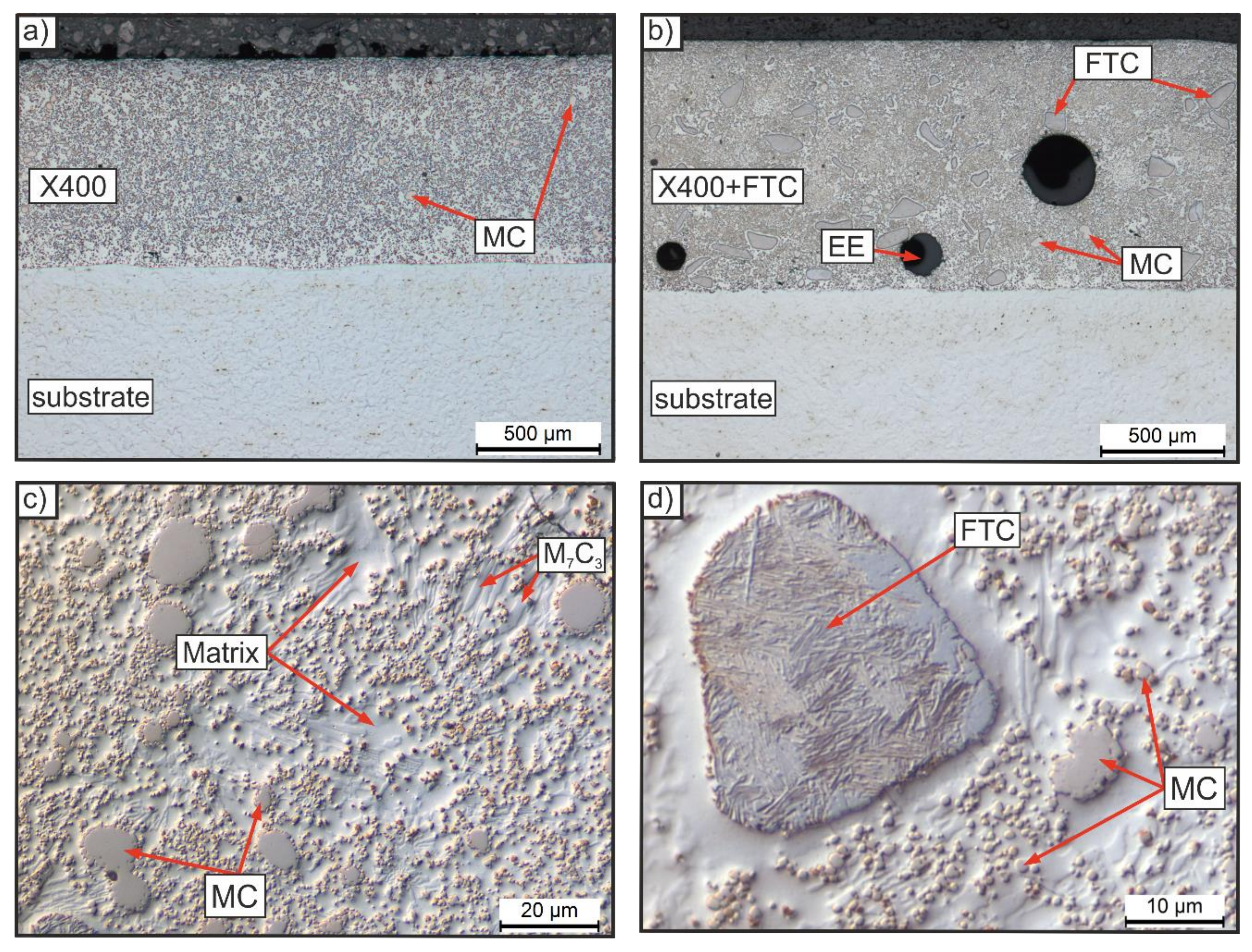
To obtain reinforced metal matrix composites (MMC), fused tungsten carbides were added to the slurry during the mixing process. In this work, the unreinforced hardpaint coatings are named X400 and the reinforced coatings X400 + FTC. Due to the high amounts of the carbide forming elements vanadium and chromium, both coatings contain high volume fractions of dispersed vanadium-rich MC-carbides and chromium-iron carbides of M7C3 type. Moreover, the added FTCs of the MMC are visible. Figure 1 shows the microstructures of the two coatings. The volume fraction of the FTC was determined by image analysis and is about 10 vol.% [20].
The function of the enamel is bonding the metal particles together and to the substrate, until they start to melt and bond themselves. In the best case, the whole enamel comes to the surface during the heating process. However, a certain amount (~18 vol.%) of enamel inclusions (EE), which have proven to be brittle and not wear-resistant, remained in the coatings [20]. These globular inclusions are easy to identify with the microscope as well. To reduce the EE, the process parameters (e.g., movement speed of the inductor, distance between inductor and sample) have to be optimized in further research.
To prepare the samples for further investigations, they were first sandblasted after the coating process to remove the glassy binder from the surface. Then, they were ground flat and finished to size—cubic samples with a surface area of 12 mm × 12 mm. After that, the samples for the microstructure investigations, the hardness measurements and scratch tests were additionally embedded in epoxy resin and prepared metallographically. The grinding process was carried out using SiC papers (P180, P320, P600, P1000). The polishing was carried out in 2 stages with 6 μm and 3 μm diamond suspension. Finally, with the exception of the scratch test samples, the surfaces were finished with SiO2 suspension.

2.2. Heat Treatment

Based on thermodynamic calculations, two different heat treatment routes (HTR) were worked out to modify the wear behavior of the unreinforced coatings. The calculations were performed with Thermo-Calc 2016a and the TCFE7 database (Thermo-Calc AB, Stockholm, Sweden). The chemical composition of the alloy specified by the manufacturer was used, Table 1.
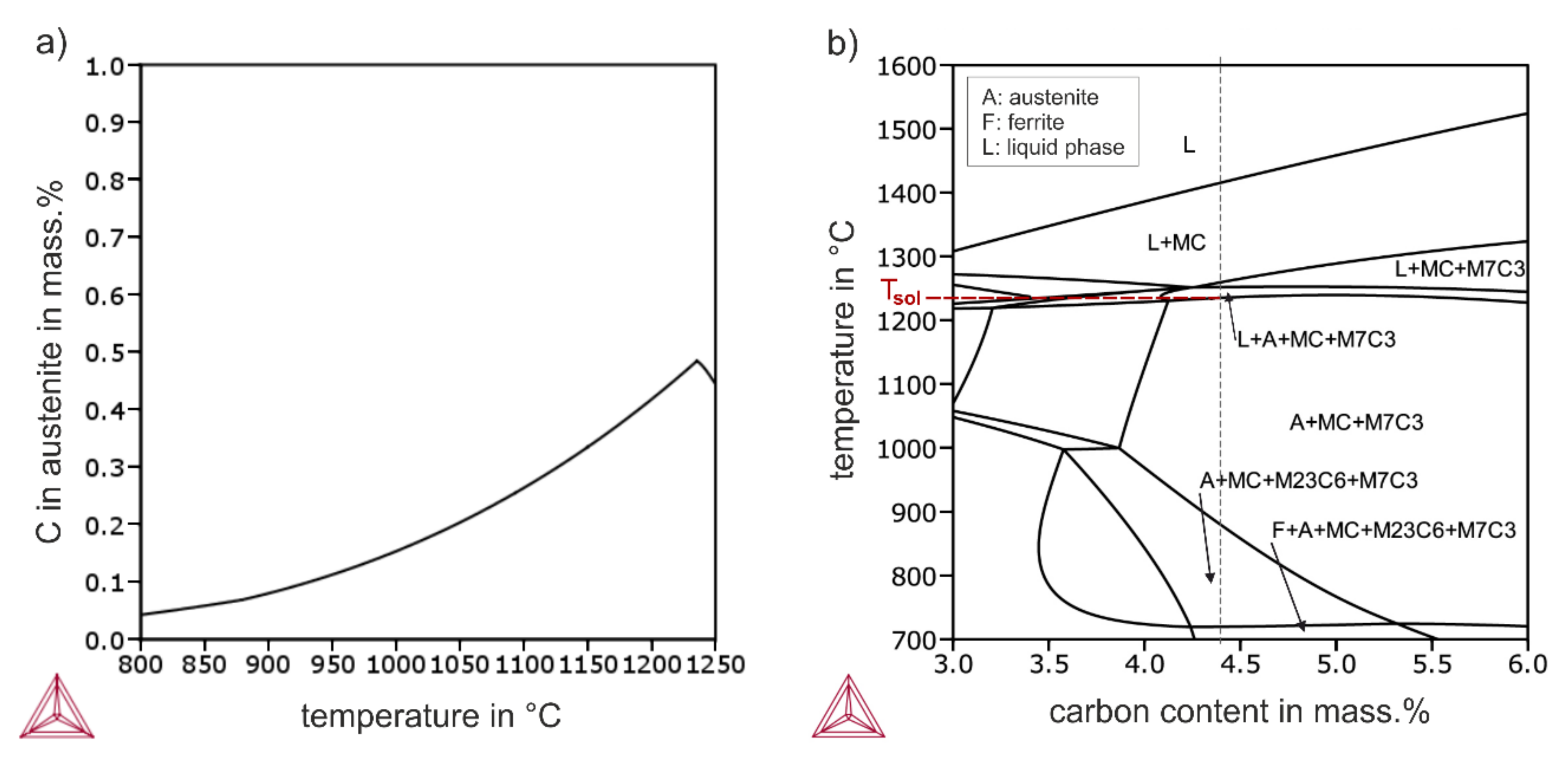
To increase the hardness of the microstructure, it is necessary to dissolve an adequate amount of carbon in the austenite phase—therefore, the austenitization temperature of HTR 1 was determined pretty close to Tsol at 1200 °C, Figure 2. For this temperature, the Thermo-Calc calculation gives an amount of 0.42 mass.% carbon in the austenitic matrix.
To achieve a microstructure that is tougher than the as-processed condition, a high amount of RA was required. The amount of RA is dependent on the Mf and the Ms temperature. The Ms temperature was estimated with the modified empirical formula of ‘Steven and Haynes’, Equation (1) [22]. For this purpose, the amounts of the alloying elements (mass.%) of the austenite at the specific temperature were calculated with Thermo-Calc, Table 2.
Ms [°C] = 561 − 474 C − 33 Mn − 17 Cr − 17 Ni − 21 Mo + 10 Co − 7.5 Si
Due to the distinct influence of carbon, higher austenitization temperatures cause lower Ms temperatures, Table 2. To obtain as much RA as possible, the austenitization temperature of HTR 2 was also set quite close to Tsol at 1200 °C. Based on the determined Ms value of 28 °C, it was assumed that a high amount of RA would remain in the microstructure, because the martensitic transformation would not have proceeded significantly after quenching to RT.
Due to the expected retained austenite, as previously mentioned, a cryogenic treatment step was added to the HTR 1 to transform most of the RA into martensite. The heat treatment parameters of both HTRs are summarized in Table 3. The austenitization heat treatment was carried out with a ROF 7/75 tubular vacuum furnace (max. temperature 1300 °C) from Heraeus (Hanau, Germany). The minimum pressure realized was 4.4 × 10⁻² mbar. During the heating process, the vacuum pump was stopped at 450 °C and the chamber was then flooded with argon (up to ~400 mbar). The low-temperature tempering processes were performed with a Venti-Line drying oven (max. temperature 300 °C) from VWR International GmbH (Darmstadt, Germany). The deep cryogenic treatment was carried out with a Dewar vessel filled with liquid nitrogen. There, the samples were placed on a floating grid, which was placed 40 mm from the surface of the liquid.

2.3. Laser Scanning Microscopy

A VK-X250 laser scanning microscope (LSM) from Keyence Deutschland GmbH (Neu-Isenburg, Germany) was used to examine the surface of the coatings. This microscope not only enables the recording of two-dimensional images with high depth of field, but also the creation of high-precision (resolution: 0.5 nm) three-dimensional surface images, as well as the visualization and measurement of height profiles. There is also the option of analyzing the volume that is below or above a defined reference level in a selected area, e.g., the volume of surface breakouts. In this work, various wear grooves created after the wear tests were investigated qualitatively and quantitatively with the LSM.

2.4. Wear Tests

2.4.1. Scratch Test

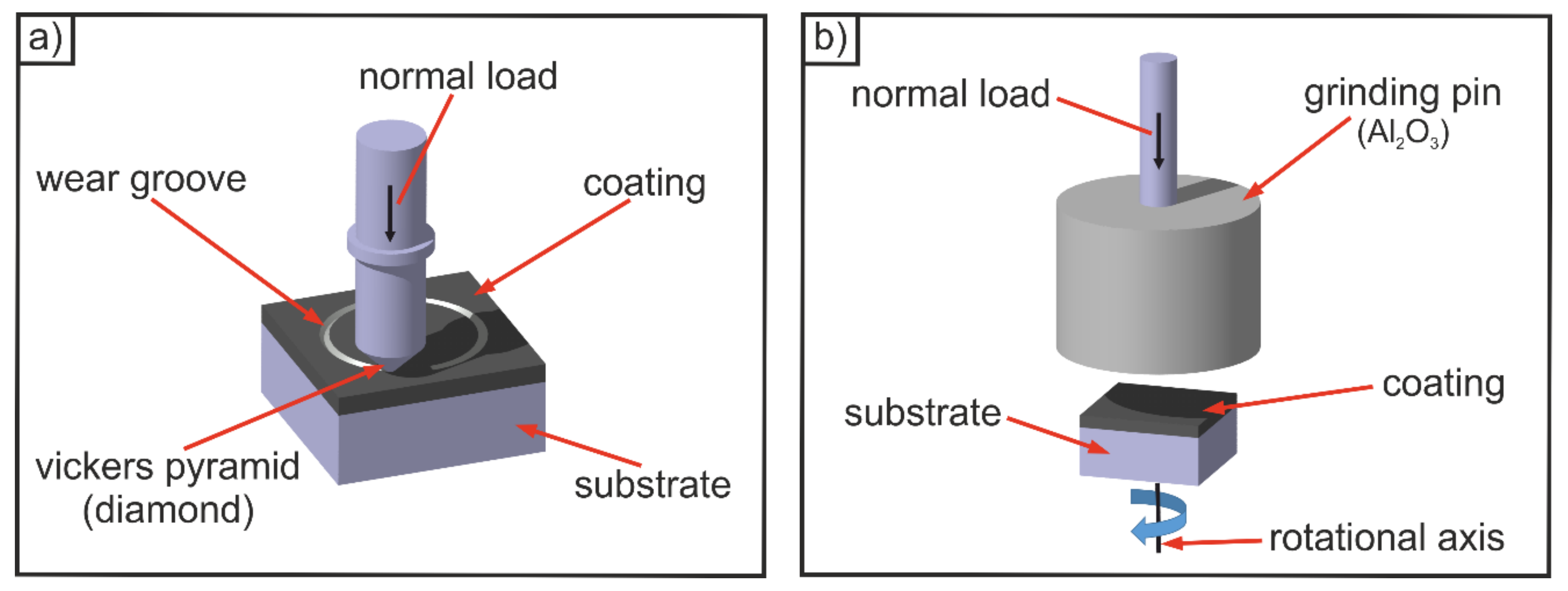
To examine the influence of heat treatment on the abrasive wear resistance of the hardpaint coatings, scratch tests were carried out using a TRM 1000 tribometer from Wazau Mess- und Prüfsysteme GmbH (Berlin, Germany). The experimental setup is schematically shown in Figure 3a. A pyramidal diamond indenter was used as a counter body to generate wear grooves on the polished layer surfaces. The set normal load was 5 N and the speed ~0.7 mm s−1. The generated groove is one single scratch channel (test duration < 1 round) on a circular path with a diameter of 8 mm. The intention of the scratch test is to create single wear grooves under the same conditions, which are then comparatively analyzed using laser scanning microscopy.

2.4.2. Abrasion Wear Test

The abrasion wear tests were also performed with the TRM 1000 tribometer from Wazau Mess- und Prüfsysteme GmbH, to investigate the abrasive wear resistance of the hardpaint coatings and the influence of the hard particle reinforcement. Figure 3b shows the experimental setup schematically. A grinding pin of white corundum (>99.9% Al2O3) from Lukas Erzett GmbH u. Co KG (Engelskirchen, Germany) with grain size F60 according to DIN ISO 8486-1 [23] was used as a counter body. In this test, the grinding pin was pressed against the surface of the rotating sample. The set normal load was 500 N and the rotation speed 60 rpm. There was a 30-min running-in process before the start of the experiment. The effective duration of the test was 6 h. After every 2 h, there was a short interruption to remove the wear particles from the contact area using oil-free compressed air. New counter bodies were used for the running-in process and the test. Before the start of the test and after the end, the samples were first cleaned in an ultrasonic bath with ethanol for 10 min, and then the sample weight was determined with the precision measuring balance (resolution: 0.0001 g). The complete test was carried out twice for each coating.
The experiment aimed to determine the wear resistance of the protective layers against abrasion, and to compare them with one another. For this purpose, the volume losses were calculated based on the measured mass losses (arithmetic mean of test 1 and test 2) and the density values, which were determined by pycnometry in [18]. The volume loss of the tested sample divided by the contact area gave the height loss.
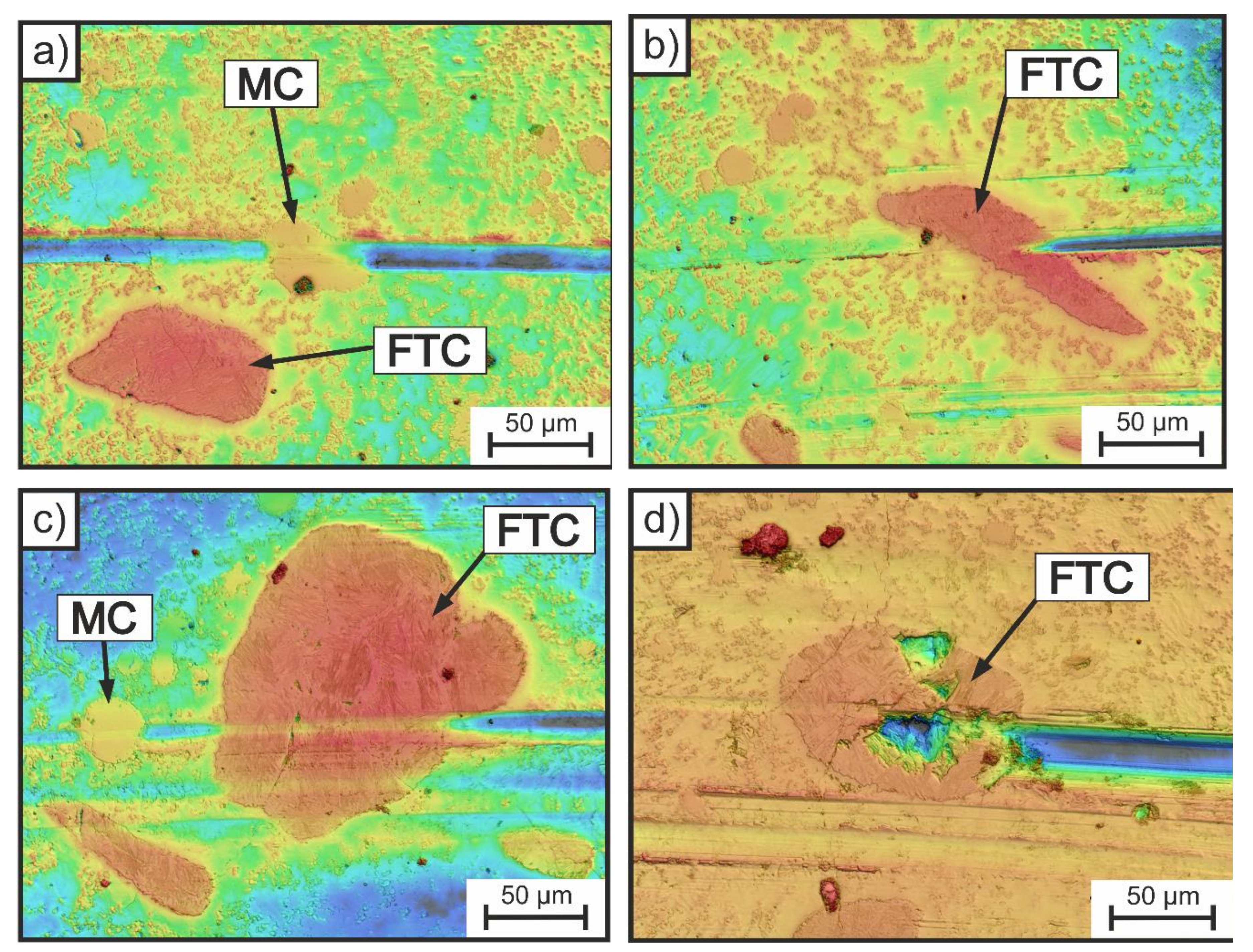
Because of the long duration of the long-term test, the reactions of the various hard phases of the coatings cannot be analyzed microscopically [18]. Duo to this, a short-term test was also carried out to examine the influence of particle reinforcement and the wear-reducing mechanisms of the hard phases in the present tribological system. The conditions were the same, but the test ended after a quarter turn. The surface of the tested coating X400 + FTC was previously prepared metallographically. After the end of the test, single wear processes were identified with the aid of the LSM.

3. Results and Discussion

3.1. Hardness

The Vickers hardness of the coatings in the as-processed and the two heat-treated states was measured in accordance with DIN EN ISO 6507-1 [24]. The determined hardness values of the identified hard phases of the layers are given in Table 4. The finer MC-carbides and the diffusion layers around the FTCs were not tested because of their small sizes. The matrix hardness of the coatings in the as-processed state and the hardness values of the heat-treated unreinforced layers were measured and presented in Table 5.
The matrix hardness of the reinforced (X400 + FTC) and non-reinforced layers (X400) in the as-processed state is around 600 HV0.05. The heat treatment according to HTR 1 increased the hardness to ~680 HV0.05. The heat-treated layers X400 + HTR 2 that were not cryogenically treated have a significantly lower hardness, which is in the range of 430 HV0.05.
The results thus show that after quenching to RT, there is RA in the microstructure, which can be transformed into martensite by cryogenic cooling in LN2. This can be concluded based on the significantly higher hardness of the coating X400 + HTR 1, compared to the coating X400 + HTR 2. Furthermore, the results agree with the estimation of the Ms temperature. However, the accuracy of the calculation cannot be evaluated.
A higher Ms temperature is considered to be the cause of the harder matrix of the coating in the condition as-processed (compared to the coating X400 + HTR 2), which was also quenched from high temperature to RT. This may result from a lower dissolution of carbides because of the rapid melting process. Due to the lower quenching rate, a reduction of the austenite carbon content based on diffusion processes is also conceivable.

3.2. Wear Resistance and Behavior

3.2.1. Scratch Test

A higher hardness is known to lead to a lower penetration depth of the abrasive, and thus to a reduction of abrasive wear [16]. However, increasing hardness also increases the risk of unwanted microcracking and brittle failure. The influence of heat treatment on the wear resistance of the considered hardpaint coatings has not been elucidated until now. For this reason, the focus of this work is on the investigation of the heat-treated layers and the relationship between hardness and wear resistance. Therefore, the heat-treated coatings of type X400 and the same coating in the as-processed state were first scratched and then analyzed using LSM.
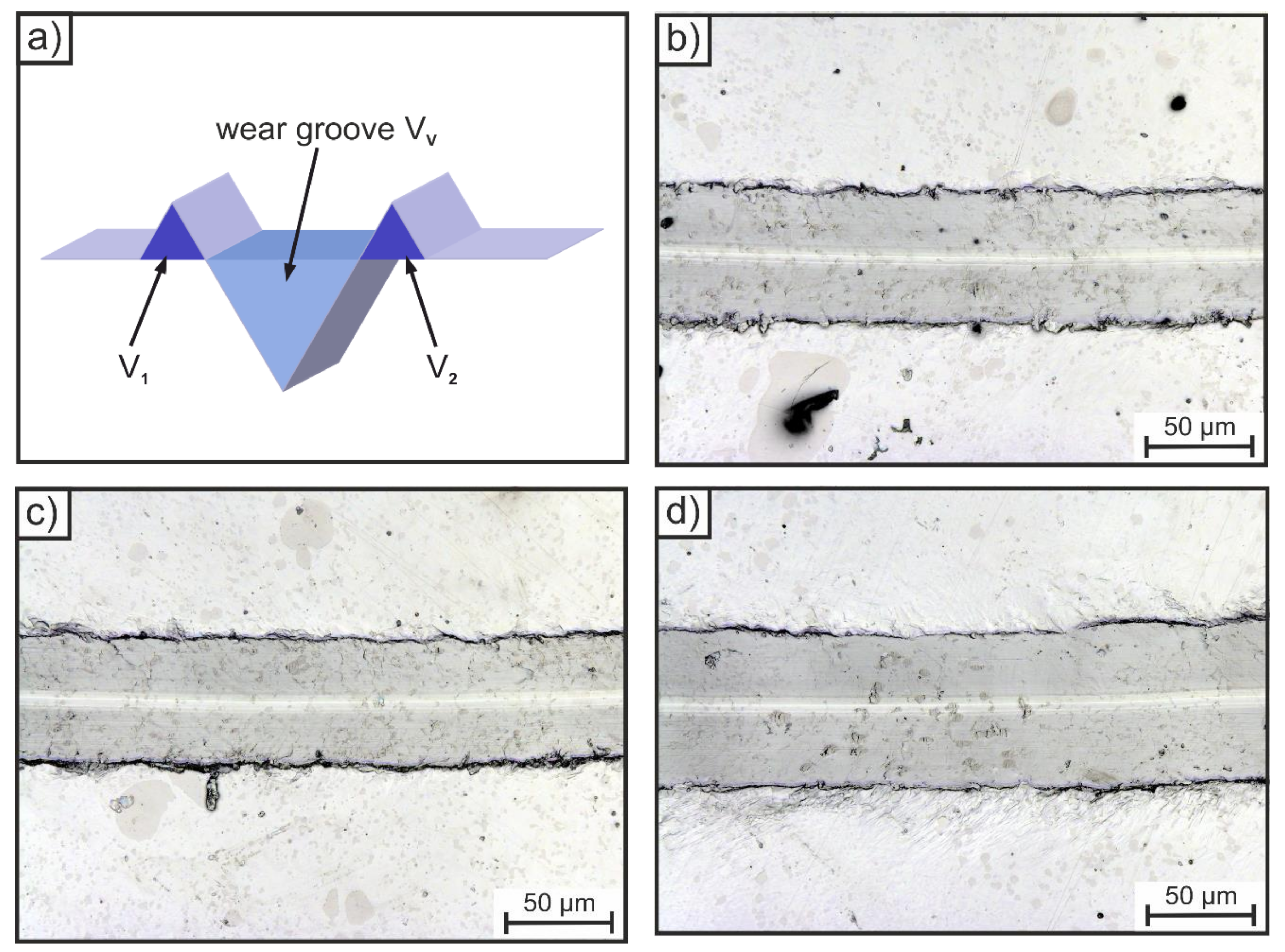
As already mentioned, with the LSM it is possible to create height profiles, e.g., to measure the depth or the cross-sectional area of the wear groove. However, these are only local measurements. In order to analyze a larger area, the volume of the furrow VV was set as the characteristic value in this study, Figure 4a. A higher volume VV means a higher wear rate and a lower wear resistance, respectively.
The unaffected surface outside the furrow was set as the reference level, below which volume VV was determined. To reduce the measurement effort, three sections of equal size (S1 to S3) were measured for each sample instead of the whole furrows, Table 6. The size of a measuring section can be seen from Figure 4b–d, in which the sections S1 are shown exemplary for each sample. Based on the results of the three sections, the mean values were determined and the unreinforced layers X400 were then compared. The layer X400 in the as-processed state has a mean value of 22,042 µm3. The heat-treated layer X400 + HTR 1 has the lowest value (VV = 20,384 µm3), whereas the average furrow volume of the layer X400 + HTR 2 is the largest (VV = 37,317 µm3). This proves that the harder matrix of the coating X400 + HTR 1 counteracted the penetration of the indenter more effectively than the softer matrices of the other coatings X400 and X400 + HTR 2. As an interim conclusion, it can be noted that increasing the matrix hardness of the hardpaint coatings examined leads to a reduction of the wear groove.
Further, there are no hints for unwanted microcracking processes. The results also show that all coatings are relatively ductile. This can be seen by the volume of the material displaced to the groove sides (V1 + V2), which is almost as large as the volume of the furrow, and the low fab, respectively, Table 6. The fab-value includes the ratio of the various volumes, Equation (2) [25,26]:
fab = (VV − V1 − V2)/VV
A low fab-value indicates that the process microploughing has predominated. Pure microploughing has a fab = 0, which means that there is no loss of material, whereas a value above 1 indicates that microcracking processes have occurred. The microscopic images agree with the quantitative results, no cracks or breakouts can be identified, Figure 4b–d.

3.2.2. Abrasion Wear Test

The results of the long-term abrasion wear test are shown in Table 7. Because of the addition of FTC, the coating X400 + FTC has a significantly higher specific density than the non-reinforced protective layers of type X400. Due to this fact, the volume and the height losses were determined, in order to be able to compare the results. However, the height loss is a more useful characteristic value, because this value includes both the specific density and different contact areas between the grinding pin and the quadratic surface of the sample (standard contact area ~1.44 cm2) [18].
The protective layer X400 + FTC, with a height loss of 5.0 μm, has the highest abrasive wear resistance of the examined samples. The non-reinforced coating X400 in the condition as-processed has lost ~13.8 μm in height and therefore a lower wear resistance than the protective layer X400 + FTC. As mentioned before, there is usually a relationship between hardness and abrasive wear resistance. As already shown, the matrix hardness of the coating X400 was modified by different heat treatment routes. The height loss of the heat-treated coating with the hardest matrix (X400 + HTR 1) is about 20% less than that of the coating X400 in the condition as-processed. Contrary to this, the wear resistance of the layer X400 + HTR 2 is distinctly lower, as can be seen from the high loss of height.
The results of the long-term abrasion wear test thus confirm that the relationship between matrix hardness and wear resistance applies to the hardpaint layers investigated. They also agree with the findings of the scratch tests. In particular, the results prove that it is possible to optimize the unreinforced coating X400 in the as-processed state by heat treatment.
However, the addition of FTC is a more forceful measure to reduce wear. The requirement [17] that the stressed hard particles must have at least ~1.2 times the hardness of the attacking abrasives (hardness Al2O3 ~2100 HV 0.05 [16]) to have a significant wear-reducing influence agrees with the positive effect of the FTC on the wear resistance. It is also necessary that the carbides are of sufficient size to counteract the abrasive particles—smaller carbides have a significantly lower influence or, in the worst case, are lifted out of the furrow [16].
The findings of the short-term abrasion wear test prove that the FTC are of sufficient size, because the wear grooves are generally smaller than the added hard particles, Figure 5. Therefore, the carbides usually interrupted the furrow processes or reduced the size of the groove. However, the reactions of the FTC were different. Some of them were kept almost undamaged (Figure 5b,c), whereas other FTC were partially destroyed (Figure 5d). Furthermore, it can be observed that the coarser vanadium-rich MC-carbides also have a significant impact on the wear behavior. This can be deduced from the tapered furrows in the carbide zones, Figure 5a,c. The high amount of the MC is mainly responsible for the high abrasive wear resistance of the unreinforced coatings X400, which are more resistant than commonly used martensitic steels without hard phases like Hardox 450 [18]. The reactions of the smaller M7C3-carbides were not identified. However, due to their small size and low hardness, the result that the influence of these carbides on the wear resistance is not as significant as that of the coarser hard phases analyzed is understandable.

4. Conclusions

The investigations have shown that it is possible to modify the hardpaint coating X400 by heat treatment. The performed heat treatment route 1 is able to increase the matrix hardness due to martensite formation. Further, the results of the scratch test proved that a higher matrix hardness led to a lower penetration depth of the diamond indenter into the coating surface. The positive influence of the heat treatment was also evident by the reduction of abrasive wear. However, the wear-reducing effect of particle reinforcement with FTC is obviously higher, but no statements can be made about the optimal amount of hard particles in the hardpaint coating. Further research should focus on this aspect. The costs for both optimization options (particle reinforcement and heat treatment combined with deep cryogenic treatment) should also be taken into account and reduced in further studies. Moreover, the results have shown that the wear resistance of the hardpaint coatings examined is also based on coarser vanadium-rich MC-carbides, which are able to interrupt the furrow processes.

Author Contributions

P.S. performed the investigations and wrote the manuscript; F.D. and S.W. helped with constructive discussions and performed the manuscript review. All authors have read and agreed to the published version of the manuscript.

Funding

This research received no external funding.

Acknowledgments

The investigated hardpaint coatings were produced at the Münster University of Applied Sciences in the Mechanical Engineering Department (teaching and research area of ‘Werkstofftechnik’). Special thanks go to J. Peterseim for the good cooperation. Further, we acknowledge support from the Open Access Publication Fund of the University of Wuppertal.

Conflicts of Interest

The authors declare no conflict of interest.

References

  1. Czichos, H. Tribologie-Handbuch; Springer Fachmedien: Wiesbaden, Germany, 2010. [Google Scholar]
  2. Deters, L.; Fischer, A.; Santner, E.; Stolz, U. GfT-Arbeitsblatt 7; Gesellschaft für Tribology e.V.: Aachen, Germany, 2002. [Google Scholar]
  3. Czichos, H.; Hennecke, M. HÜTTE-Das Ingenieurwissen, 34th ed.; Springer: Berlin/Heidelberg, Germany, 2012. [Google Scholar]
  4. Theisen, W. “Metal Matrix Composites” widerstehen dem Verschleiß: Walzen aus Pulver. Maschinenbau RUBIN 2004, 90–95. Available online: https://news.rub.de/sites/default/files/2004_maschinenbau.pdf (accessed on 17 May 2018).
  5. Bobzin, K. Oberflächentechnik für den Maschinenbau, 1st ed.; Wiley-VCH: Weinheim, Germany, 2013. [Google Scholar]
  6. Hill, H.; Weber, S.; Raab, U.; Theisen, W.; Wagner, L. Influence of processing and heat treatment on corrosion resistance and properties of high alloyed steel coatings. J. Therm. Spray Technol. 2012, 21, 987–994. [Google Scholar] [CrossRef]
  7. Fischer, A. Hartlegierungen auf Fe-Cr-C-B-Basis für die Auftragschweißung; VDI-Verlag: Düsseldorf, Germany, 1984. [Google Scholar]
  8. Theisen, W. Hip cladding of tools. In The Use of Tool Steels: Experience and Research, Proceedings of the 6th International Tooling Conference, Karlstad University, Karlstad, Sweden, 10–13 September 2002; Bergström, J., Fredriksson, G., Johansson, M., Kotik, O., Thuvander, F., Eds.; Karlstad University: Karlstad, Sweden; pp. 947–960.
  9. Blüm, M.; Hill, H.; Moll, H.; Weber, S.; Theisen, W. SintClad: A new approach for the production of wear-resistant tools. J. Mater. Eng. Perform. 2012, 21, 756–763. [Google Scholar] [CrossRef]
  10. Serafinski, D.; Winkelmann, R. Wear resistant coatings by inductive cladding (InduClad). Mater. Sci. Eng. Technol. 2014, 45, 496–503. [Google Scholar] [CrossRef]
  11. Berns, H.; Theisen, W.; Scheibelein, G. Ferrous Materials. Steel and Cast Iron; Springer: Berlin/Heidelberg, Germany, 2008. [Google Scholar]
  12. Weber, S. Gefügedesign Hochlegierter Stähle unter Berücksichtigung Werkstofftechnischer Aspekte, 1st ed.; Verlag des Lehrstuhls Werkstofftechnik (Ruhr-Universität): Bochum, Germany, 2013. [Google Scholar]
  13. Blüm, M. Neuartige Schichtverbundwerkstoffe zur Standzeiterhöhung Verschleißbeanspruchter Werkzeuge für die Mineralverarbeitung; Verlag des Lehrstuhls Werkstofftechnik (Ruhr-Universität): Bochum, Germany, 2014. [Google Scholar]
  14. Oppenkowski, A. Cryobehandlung von Werkzeugstahl; Verlag des Lehrstuhls Werkstofftechnik (Ruhr-Universität): Bochum, Germany, 2011. [Google Scholar]
  15. Baldissera, P.; Delprete, C. Deep cryogenic treatment: A bibliographic review. Open Mech. Eng. J. 2008, 2, 1–11. [Google Scholar] [CrossRef]
  16. Berns, H. (Ed.) Hartlegierungen und Hartverbundwerkstoffe; Springer: Berlin/Heidelberg, Germany, 1998. [Google Scholar]
  17. Wewers, B.; Berns, H. Wear resistant MMC with in situ carbides. Mater. Sci. Eng. Technol. 2003, 34, 453–463. [Google Scholar] [CrossRef]
  18. Schwarz, P.; Deuerler, F.; Weber, S. Production and investigation of the wear behavior of inductively melted hardpaint coatings. Mater. Sci. Eng. Technol. 2019, 50, 1196–1206. [Google Scholar] [CrossRef]
  19. Peterseim, J. Flüssigauftragbare Einbrennbeschichtung. EP Patent No. 1880039B1, 9 May 2006. [Google Scholar]
  20. Schwarz, P.; Deuerler, F.; Weber, S.; Peterseim, J. Analysis of the Micro-Processes occurring on different wear protection layers under abrasive and impact wear using laser scanning microscopy. Pract. Metallogr. 2018, 55, 762–772. [Google Scholar] [CrossRef]
  21. NT Systemlösungen GmbH. Produktkatalog Lieferprogramm Technisches Know How, version 2017; NT Systemlösungen GmbH: Osterode am Harz, Germany, 2017. [Google Scholar]
  22. Kung, C.Y.; Rayment, J.J. An examination of the validity of existing empirical formulae for the calculation of ms temperature. Metall. Trans. A 1982, 13, 328–331. [Google Scholar] [CrossRef] [Green Version]
  23. Deutsches Institut für Normung e.V. DIN ISO 8486-1:1997: Schleifkörper aus Gebundenem Schleifmittel–Bestimmung und Bezeichnung der Korngrößenverteilung–Teil 1; Beuth Verlag: Berlin, Germany, 1997. [Google Scholar]
  24. Deutsches Institut für Normung e.V. DIN EN ISO 6507-1:2005: Metallische Werkstoffe–Härteprüfung nach Vickers–Teil 1; Beuth Verlag: Berlin, Germany, 2006. [Google Scholar]
  25. Walter, M. Tribologische und Mikrostrukturelle Aspekte des Abrasiven Warmverschleißes Einphasiger, Metallischer Werkstoffe, 1st ed.; Verlag des Lehrstuhls Werkstofftechnik (Ruhr-Universität): Bochum, Germany, 2017. [Google Scholar]
  26. Zum Gahr, K.H. Microstructure and Wear of Materials; Elsevier: Amsterdam, The Netherlands; New York, NY, USA, 2010. [Google Scholar]
Figure 1. Microstructure (optical microscope) of the hardpaint layers X400 (a) and X400 + FTC (bd).
Metals 10 00968 g001
Figure 2. Results of Thermo-Calc calculations for the alloy X400: (a) carbon content in austenite as a function of temperature; (b) phase diagram with marked solidus temperature Tsol.
Metals 10 00968 g002
Figure 3. Schematic representation of the scratch test (a) and the abrasion wear test (b), which were carried out to investigate the wear behavior and the wear resistance of the hardpaint coatings.
Metals 10 00968 g003
Figure 4. Schematic representation of a wear groove (a) and the wear grooves caused by the scratch tests: (b) X400; (c) X400 + HTR 1; (d) X400 + HTR 2.
Metals 10 00968 g004
Figure 5. Results of the short-term abrasion wear test (LSM images)—wear grooves caused by a Al2O3 grinding pin. Furrowed vanadium-rich MC-carbides (a,c) and fused tungsten carbides (bd).
Metals 10 00968 g005
Table 1. Nominal chemical composition in mass.% of the alloyed iron base metal powder X400 [21].
AlloyCSiCrMnNiMoV
X400CrVMo17-15-24.40.917.00.93.02.015.0
Table 2. Matrix composition of the alloy X400 at different temperatures calculated with Thermo-Calc. The values of the chemical elements are given in mass.%. Ms determined by the modified formula of ‘Steven and Haynes’, Equation (1).
Element1150 °C1200 °C1210 °C
Fe79.7979.1579.02
Ni4.594.564.55
Mn1.261.251.25
Mo0.930.970.97
Cr10.5210.8210.88
Si1.391.381.38
V1.181.451.51
C0.330.420.44
Ms76 °C28 °C18 °C
Table 3. Parameters of the heat treatment routes of the coating X400.
Heat TreatmentAustenitizationQuenchingDeep Cryogenic TreatmentTempering
HTR 11200 °C/1 hRT (Oil)−180 °C/24 h180 °C/2 h
HTR 21200 °C/1 hRT (Oil)-180 °C/2 h
Table 4. Determined hardness values of the investigated coatings X400 + FTC and unreinforced X400 [18]. Arithmetic mean (of at least ten individual measurements) ± standard deviation.
Hardness in HV0.05FTCMCM7C3Enamel Inclusions
X400 + FTC2491 ± 432386 ± 411295 ± 102522 ± 22
X400-2382 ± 441338 ± 113503 *
* There was only one suitable enamel inclusion for the hardness measurements.
Table 5. Determined matrix hardness of the investigated coatings X400 + FTC [18], X400 [18] and the heat-treated X400 + HTR 1 and X400 + HTR 2. Arithmetic mean (of at least ten individual measurements) ± standard deviation.
Hardness in HV0.05X400 + FTCX400X400 + HTR 1X400 + HTR 2
Matrix600 ± 25592 ± 35678 ± 14430 ± 44
Table 6. Results of the scratch tests of the coatings X400 in the conditions as-processed and heat-treated determined with the LSM—wear groove volume (VV), volume displaced to the groove sides (V1 + V2), fab-values.
Hardpaint CoatingS1S2S3Mean
VV in µm3
X40020,79722,39222,96322,042
X400 + HTR 118,96820,25821,92620,384
X400 + HTR 238,42038,81934,71137,317
V1 + V2 in µm3
X40018,99019,67820,06419,577
X400 + HTR 116,80917,69918,85317,787
X400 + HTR 233,63137,49332,96734,697
fab
X4000.090.120.130.11
X400 + HTR 10.110.130.140.13
X400 + HTR 20.120.030.050.07
Table 7. Results of the long-term abrasion wear tests for determining the abrasive wear resistance of the hardpaint coatings.
ParameterUnitX400 + FTCX400X400 + HTR 1X400 + HTR 2
Mass loss (test 1)mg5.313.410.119.5
Mass loss (test 2)mg5.812.810.221.8
Mass loss (mean)mg5.613.110.220.7
Density [18]g cm−37.86.66.66.6
Contact areamm2142.44143.64143.52133.58
Volume lossmm30.711.981.543.13
Height lossµm5.013.810.723.4