Review

Recent Advances in the Control of the Degradation Rate of PEO Treated Magnesium and Its Alloys for Biomedical Applications

Department of Chemical Engineering, Materials and Industrial Production, University of Napoli Federico II, Piazzale Tecchio 80, 80125 Napoli, Italy
*
Author to whom correspondence should be addressed.
Metals 2020, 10(7), 907; https://doi.org/10.3390/met10070907
Submission received: 10 June 2020 / Revised: 1 July 2020 / Accepted: 6 July 2020 / Published: 7 July 2020
(This article belongs to the Special Issue Metallic Biomaterials Surface Engineering)

Abstract

:
Mg and Mg alloys have been studied for almost two centuries; nevertheless, commercial biomedical devices are still not available. The main issue that limits their use in the biomedical field is the rapid degradation rate combined with suitable surface properties. Novel approaches need to be designed for the development of biodegradable Mg-based devices, which could include the use of multifunctional coatings and/or new alloys designed “ad hoc”. The present article reviews on various properties, parameters and improvement methods concerning plasma electrolytic oxidation (PEO) coatings on Mg alloys substrates for biomedical applications. In this regard, (i) optimizing the PEO parameters, (ii) using additives and nanoparticles, (iii) creating combined layers of hard and/or soft particles, (iv) coating the PEO layer with a biodegradable polymer, could be the way to control their degradation rate. The review of recent scientific articles highlights that none of the techniques proposed may be preferred over the others and the need to deepen the studies for allowing the use of Mg-based devices in the biomedical field.

1. Introduction

It is well known that magnesium and magnesium alloys possess remarkable functional properties such as low density, high strength to weight ratio, good thermal and electrical conductivity, proper castability, good machining, and biocompatibility. Therefore, their use in various industries such as automotive, aerospace, entertainment and more recently in the bio-medical field is increasing [1,2]. Despite the numerous advantages, they have some drawbacks which have restricted their applications. Low elastic modulus, finite cold workability and toughness, low creep resistance at high temperatures, and chemical reactivity are some of these shortcomings [1]. In particular, the high reactivity has limited their use in several industrial fields, due to the resulting high degradation rate when exposed to ambient or aggressive environments. Different methods, such as surface modifications and/or coatings, are proposed to overcome these flaws [1,3]. Further, Mg alloys have attracted attention for biological applications because of their biodegradation ability [4]. Mg2+, as the fourth most abundant cation in the human body, is a fundamental element, with a daily dosage of 300–400 mg of Mg suggested for adults. It is reported that an additional amount Mg intake could be innocuous and excreted in the urine [5]. New reports have represented the advantages of Mg on the growth and strength of bones [6]. Moreover, Mg alloys with a specific density and Young’s modulus of 1.74–2 g/cm3 and 41–45 GPa, respectively, have the most close values to those of the bones of the human body (1.8–2.1 g/cm3, 3–20 GPa) in comparison to other typical materials used as implants. Ti alloys, Co-Cr alloys, as well as stainless steels, have a density and Young’s modulus more than 4 g/cm3 and 110 GPa, respectively. The mismatch between the properties of Ti alloys, Co-Cr, etc. and natural bone tissue resulting in stress shielding effects can lead to reduced stimulation of new bone growth [7]. Accordingly, Mg alloys could have the edge on other metallic or polymeric materials for orthopedic, bone repairing or replacement purposes [8].
The first use of pure Mg as a biomaterial was by Huse at the end of 19th century [9], employing pure Mg wires as ligatures. Later, Lambotte, in 1909, implanted a plate of pure Mg with gold-coated steel nails in a 17-year-old teenager. After that, the papers dealing with the use of Mg alloys in the biomedical field increased, mainly in the past two decades, as demonstrated by the incremented number of articles published in scientific journals (see Figure 1).
The traditional medical devices, made of Ti alloy or other metallic materials, often require a second surgery to be removed after the tissue has been healed. This second surgery creates problems both imposing high costs to the medical system and complications for the patient. From this point of view, the biodegradability of Mg alloy devices is an added value in some biomedical applications. [2,10].
The main obstacle to using Mg alloys as biomedical implants is the evolution of a large amount of hydrogen [11] and the increase in the pH value in the surrounding medium while degrading [12,13,14]. Accumulation of the evolved hydrogen bubbles increases the healing time, implicating the tissues detachment from the device [15]. Moreover, if the build-up occurs in the cardiovascular system, it could cause blockage of the blood vessels and the death of the patient. Further, the local alkalization can influence physiological reactions and may cause serious internal injuries if the pH values surpass 7.8 [12].
A master plan to overcome these problems is to control the rate of Mg corrosion (its biodegradation) so that the release of Mg2+ and OH ions, as well as H2 gas, are gradually developed, to give enough time to the body for adjusting to and handling the byproducts of biodegradation.
Mainly, two techniques can be utilized to improve the corrosion resistance of Mg alloys [16]:
(i)
Adjusting its composition and/or microstructure, including the grain size [17,18,19] and texture [20], or by alloying [21,22].
(ii)
Coating the substrate [23] producing protective layers made of ceramic, polymeric or composite materials [16,24,25].
Several reviews are available in the literature related to the modification of the Mg alloys bulk composition or the surface modifications techniques [26,27,28]. This paper aims to point out the most recent results obtained by coating the Mg alloys using plasma electrolytic oxidation (PEO), in order to control their degradation rate in a biological environment.

2. The PEO Process

The PEO process is originating from the anodic oxidation one. The latter is the most commercially employed coating technology for Mg alloys [23]. Nevertheless, the coats obtained using the PEO process have many advantages compared to the conventional anodizing methods. Higher hardness values, thicker coating (up to 200 µm), higher wear resistance, increased corrosion resistance and better fatigue properties are the prerogatives of PEO coating [29,30].
The PEO process, which is also known as micro-arc oxidation (MAO), plasma-chemical oxidation (PCO), anodic spark oxidation (ASO), and anodic spark deposition (ASD), employs high voltages—higher than dielectric failure potential of the passive films—to modify the substrate surface. The discharges created at the surface/electrolyte interface cause localized melting/remelting of the substrate and formation of oxides well adherent to the substrate, as well as an elaborate topography [31]. PEO is a complex process involving chemical and electrochemical reactions as well as phase transitions. It is affected by various parameters such as the substrate, the electrolyte composition, the applied voltage or the current density, the mode of power supply, the pulse frequency, the duty cycle, and the duration of the process [32].
A typical experimental setup for PEO treatment is depicted in Figure 2. It consists of the jacketed vessel, the cooling system to control the cell temperature, the mixing apparatus, the power supply, the cathode (a platinum or stainless steel electrode), and the sample which acts as anode.

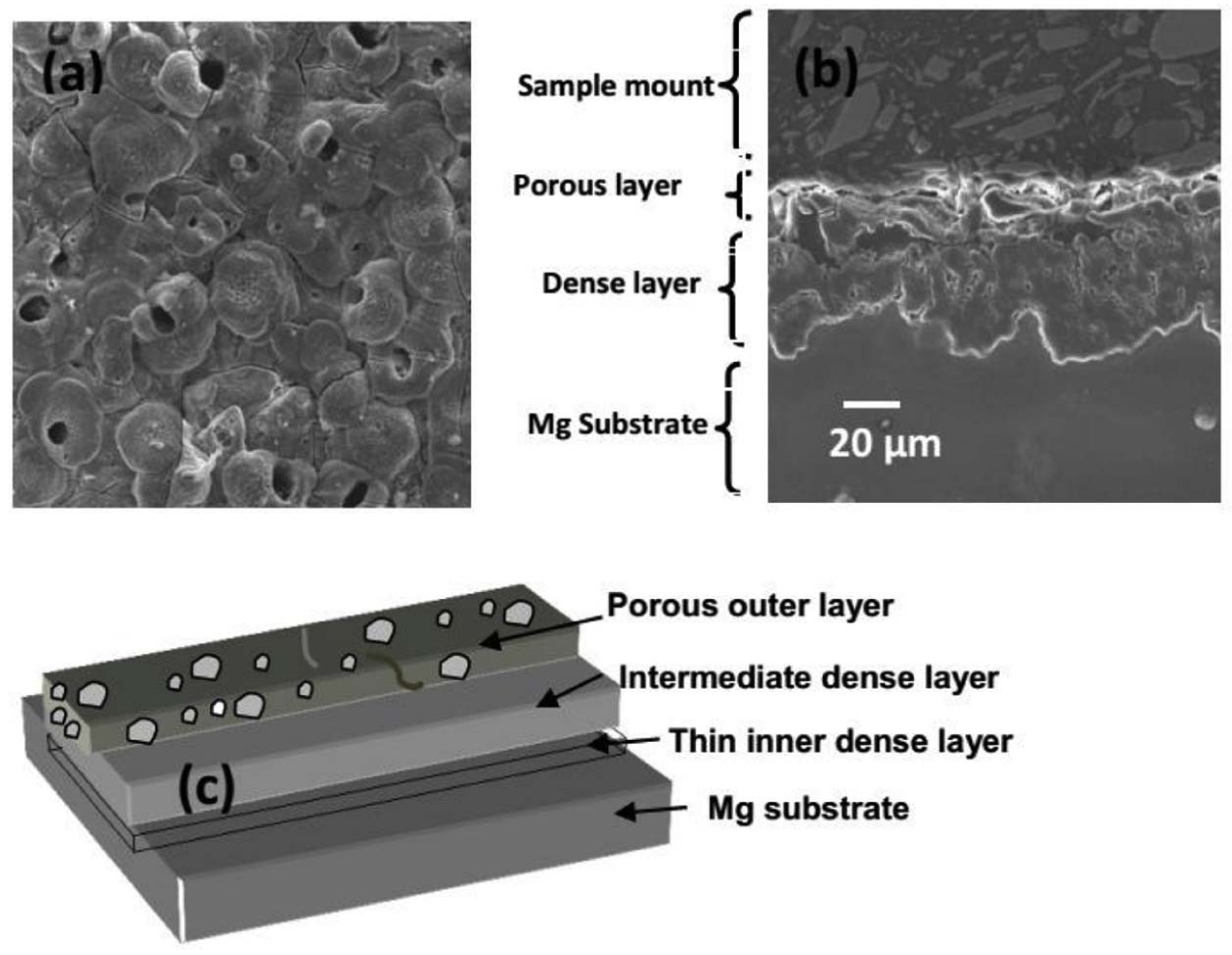
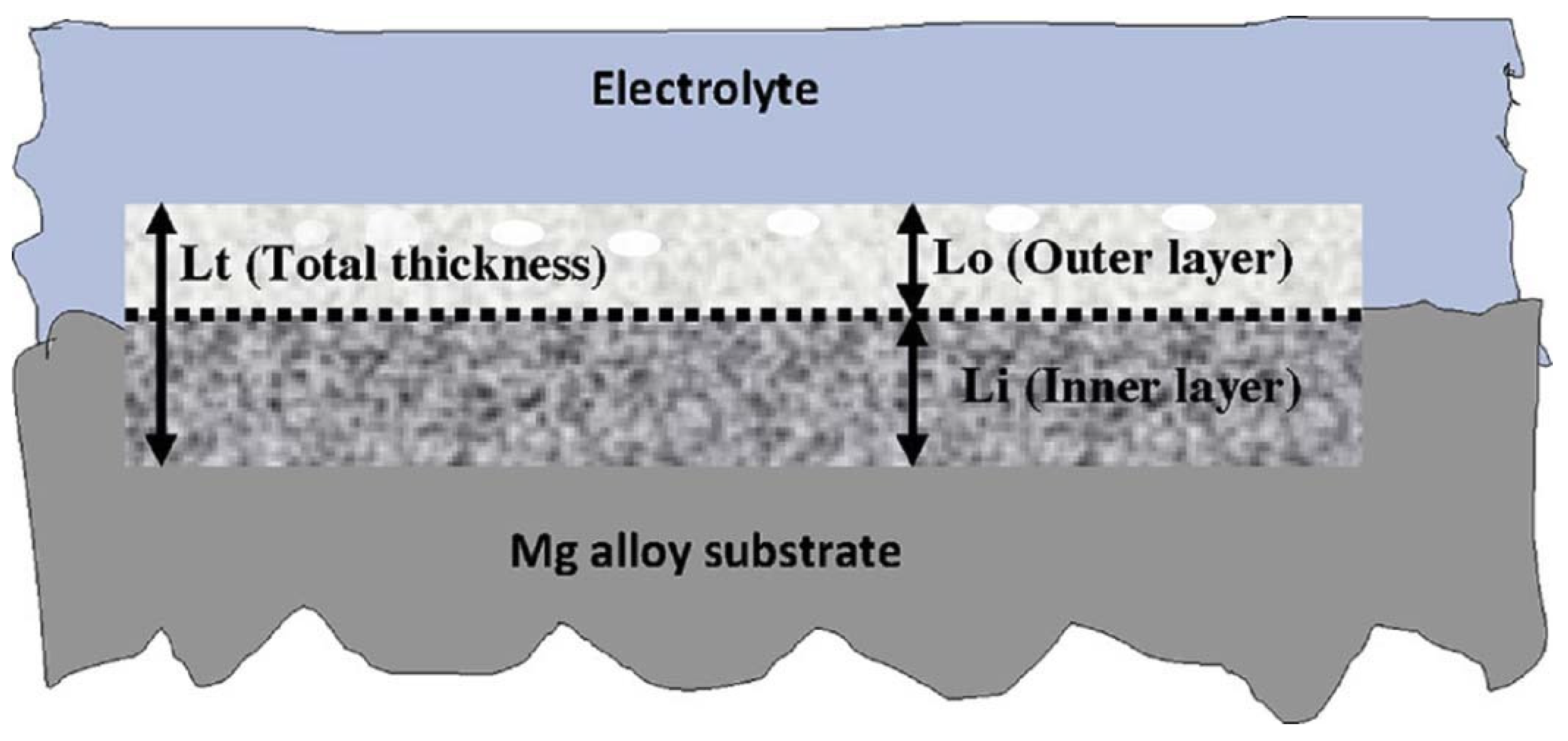
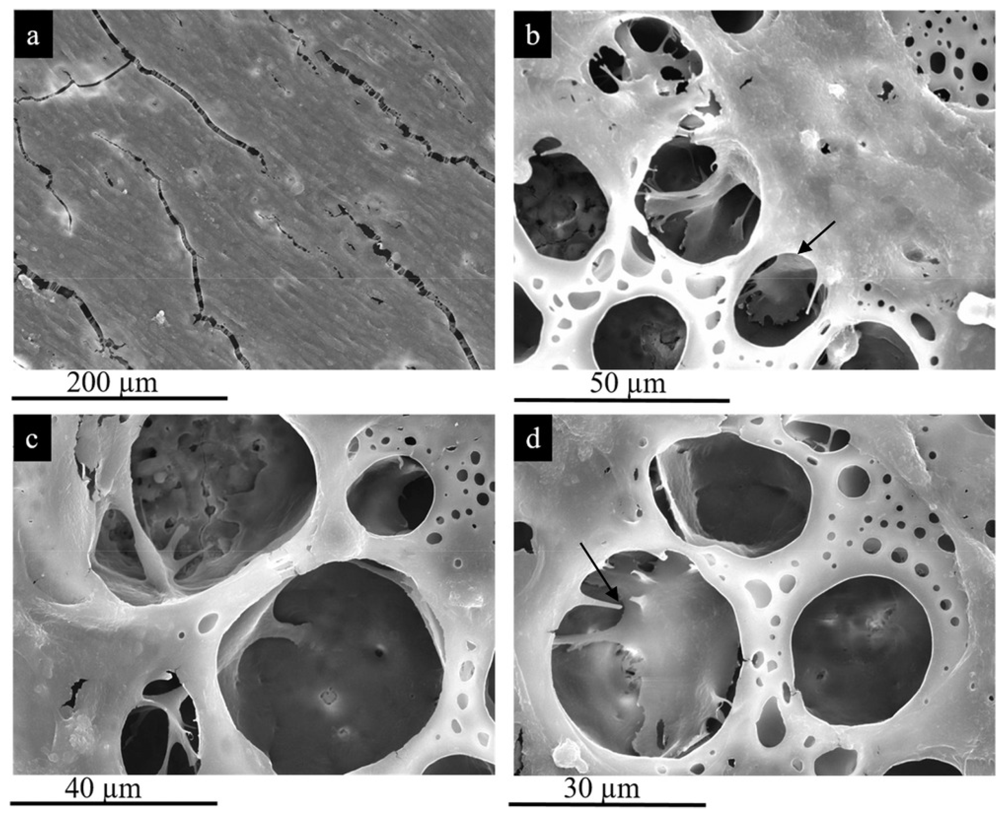
2.1. PEO Layer Structure

The chemical composition of the solution is the most examined parameter to try to increase the PEO layer performances. The electrolyte composition affects both the physical characteristics of the discharge and the layer chemical composition. Alkaline electrolytes are the most commonly exploited medium for PEO treatment of Mg alloys. Phosphates, silicates, and aluminates can be considered as prevalent additives for electrolytes in PEO of Mg alloys. Ghasemi et al. observed that the PEO coatings were remarkably thinner with a smoother surface and smaller pore size using silicate electrolytes if compared to phosphate-based electrolytes [34]. Several reviews pay specific attention to study the effect of the electrolytic composition on the characteristics and properties of the coatings formed using PEO treatments [35,36,37].
The PEO produced films (Figure 3) are composed of three distinct layers including (i) an external porous layer, (ii) an intermediate dense and thick layer, and (iii) an internal thin and compact layer, which sticks to the substrate and plays the role of a barrier. The middle layer is responsible for controlling most of the mechanical properties exhibited by the covering [38]. About one-third of the entire thickness of the PEO layer acts as a barrier layer; it is dense and is devoid of porosities and cracks, strongly linked to the substrate by sintered interlocking. Experimental results showed the lack of any discontinuity among the barrier layer and the surface of the bulk material in the bonding zone, highlighting the occurrence of a perfect bonding between the formed PEO layer and the substrate [39].
A closer look at the surface of PEO coatings reveals cauliflower or pancake-like microstructures that can be explained considering the complex chemical-physical conditions existing at the substrate/aqueous solution interface.
At the beginning of the PEO process, during the "traditional" anodizing phase, a thin oxide film with defects is formed. At the same time, many small gas bubbles develop on the surface of the sample, due to the production of O2 at the interface. The growing number of gas bubbles can cause coalescence with each other, forming a thin gaseous layer of the electrode surface. Furthermore, the difference in potential applied between the anode and the cathode, increasing during the process, drives the anions contained in the electrolyte towards the gas layers. This effect determines the formation of zones where a strong electric fields exist. It has been shown that, during PEO, extremely high temperatures, of about 900–1200 °C, can be reached in the layer being formed, and to a lesser extent, in the electrolyte in contact with it [35]. In these environments, the water can boil and the substrate can melt. In these thermodynamic conditions of high temperature and pressure, in the presence of a strong gradient of electrical potential, a plasma can be triggered. The discharge occurs initially at the points where defects in the oxide layer occur. The pores and cavities in the center of each pancakes-like structure are attributed to the going up of the molten substrate toward the surface and flowing out in the electric discharge channels. The flux of the molten substrate toward the low-temperature electrolyte and the following quenching of the melts is supposed to be the cause of formation of the holes [40]. The PEO process duration and discharge density are two main factors that affect the size of the pores, and some researches showed that pore diameter in Mg alloys is typically between 0.5 and 50 μm [35,41]
This overall view of the phenomenon allows us to explain the rapid extinction of the single plasma discharge and the ignition in other areas of the electrode. As is known, plasma is made up of an overall neutral ionized gas [42]. The high electrical conductivity of the plasma gas determines a rapid reduction in the potential gradient that generated it, thus lacking the conditions for sustaining the discharge itself, so that the plasma will switch off in these areas while it will be able to ignite in other electrode zones where the chemical/physical and electrical conditions for its ignition occur.
It is known that adherent compact oxide layers, formed on several types of metals like titanium, stainless steel, etc., grow inward and outward from the original surface. The same happens in the case of PEO treatments of Mg alloys. Figure 4 shows a schematic representation of the PEO layer growth on a metallic substrate, in which “Li” and “Lo” are the portions of oxide layer growth—inward and outward—from the original surface’s height, and “Lt” is the total coating thickness. For a given “Lt”, the ratio “Li/Lo” depends on the layer chemical composition that determines its electronic and ionic conductivity.

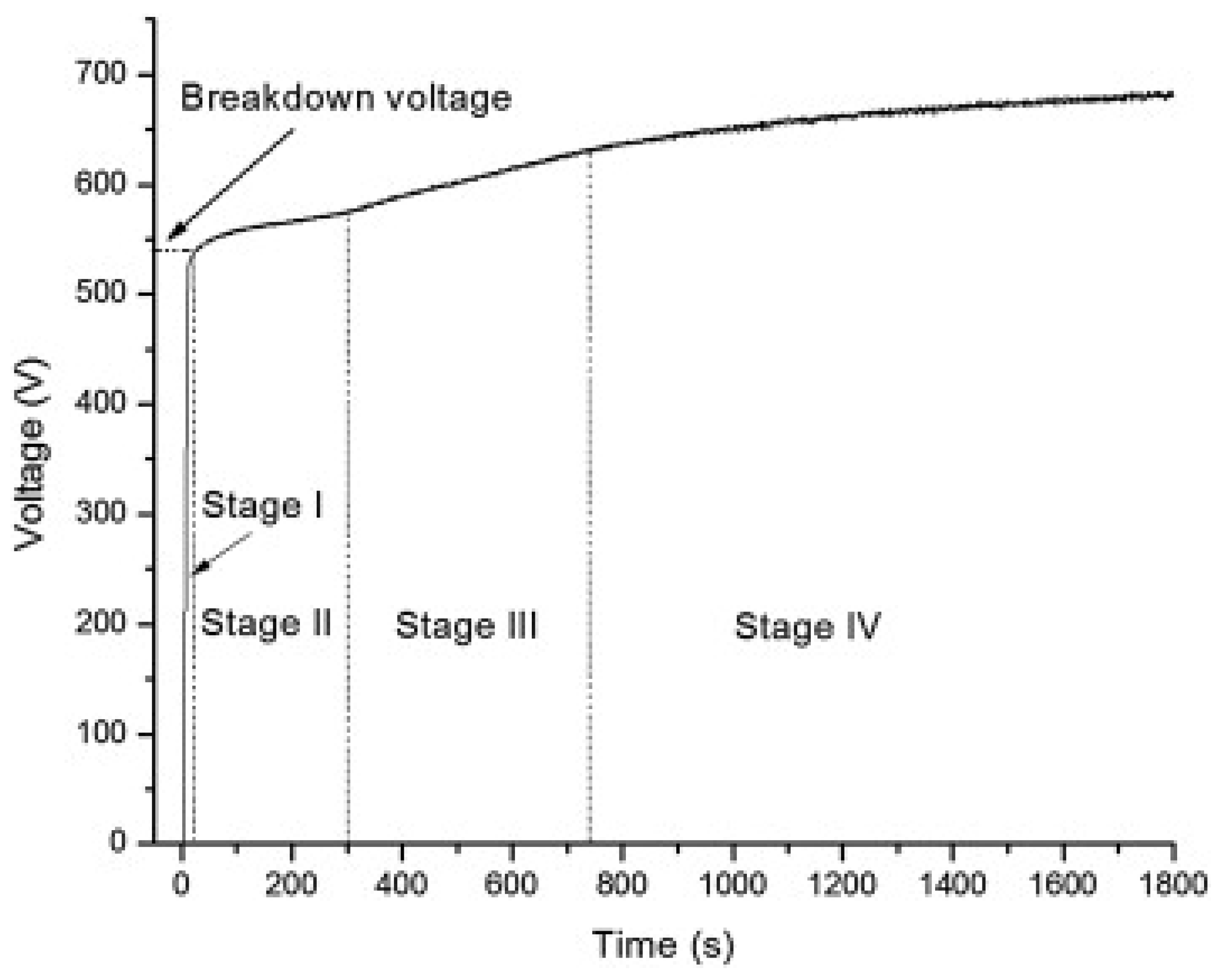
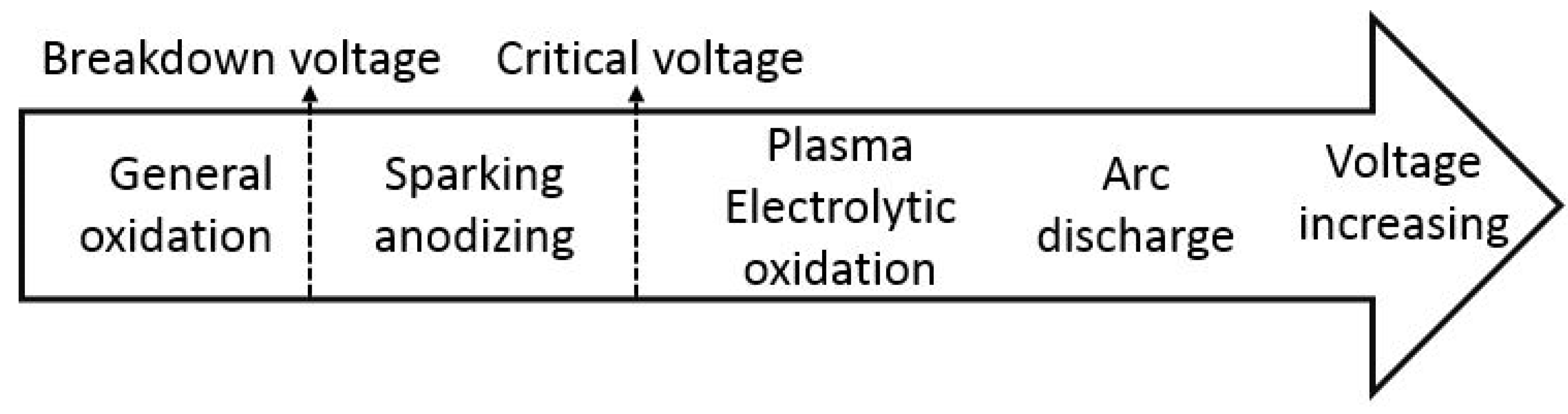
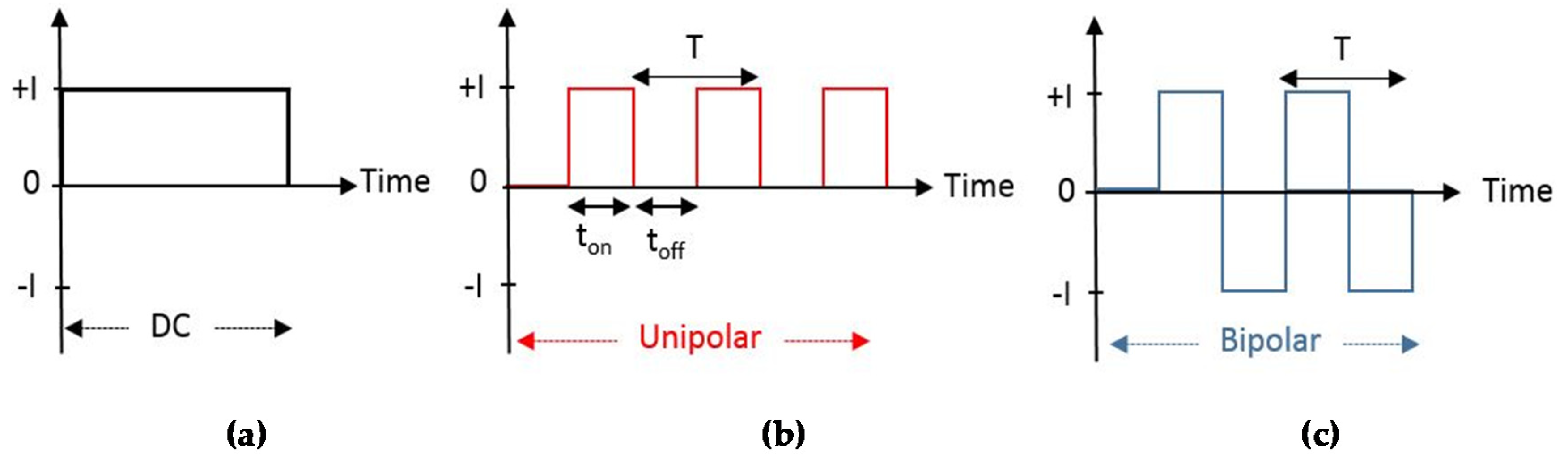
2.2. The Electrical Regime

Various types of power sources can be used to carry out a PEO process, i.e., (i) direct current (DC), (ii) pulsed direct current (PDC), and (iii) alternating current (AC). A DC regime can be applied in either galvanostatic or potentiostatic modes. Even if DC is the widely used regime in the majority of scientific papers, it does not allow complete guidance of the process due to the complications in control of the discharge features. When used in the potentiostatic mode, it enables the formation of a quasi-steady electrical double layer at the interface [43].
When using the DC constant current mode, PEO processes can be divided into four steps based on voltage variations, (Figure 5), or on phenomena occurring at the substrate surface (Figure 6). In the first stage, the voltage increases linearly with time, and no visible spark appears. In this phase, a thin transparent passive film forms on the substrate and the voltage will continue increasing until reaching the breakdown voltage. In the second period, the voltage linearly increases with time but less rapidly compared to step 1. In this stage, a large number of short white sparks appear at the anodic site that reveals the making of spark anodizing. At the end of this stage, the voltage increases to the critical voltage. The latter can considered the voltage value at which the transition from phase II to phase III occurs. The third stage starts with steady-state sparking with orange lights. In this stage, the voltage reaches a plateau at a relatively stable value, the size of the sparks gradually increases and, finally, the plasma electrolytic oxidation takes place. For more prolonged process duration, intense arc discharges appear partially destroying the oxide layer; this step is indicated as the fourth stage [44]. It should be noted that while the transition from stage 1 to stage 2 is clear, with the boundary between the two regions being sharp, the transitions from one stage to another are usually gradual and not necessarily as distinct as in the case presented in Figure 5. For this reason, some authors considered only three steps, joining together steps 3 and 4, based on the voltage-time response, and four stages based on the phenomenon occurring on the metal surface as indicated in Figure 6 [45].
As above-mentioned, when using the DC mode, the PEO treatment can be performed in constant voltage or constant current mode. In either case, as time passes, the thickness of the oxide film increases as well as its electrical resistance. Therefore, in the constant voltage method, after an initial peak, the current decreases with time, while in the constant current mode, the voltage changes by the time, to maintain the set current. In general, as the current increases, the number of pores decreases and the thickness of the coating increases [32].
More sophisticated process control can be achieved using PDC, in which the heat transfer can be controlled changing the arc duration. At the same time, this implies that the polarization due to the electrical double layer changes with the time, sometimes needing higher power consumption [43].
The AC mode can be “balanced” or “unbalanced”, meaning that the positive to negative voltage (or current) ratio can be varied. This regime determines a reduced polarization of electrodes and allows the control of the chemical composition of the forming layer [43].
Figure 7a shows that the constant current mode can be used to generate a square wave in which the current changes between 0 ↔ I. In Figure 7b,c, unipolar and bipolar current square waveforms, respectively, are presented. In these cases, the current varies between 0 ↔ I or +I ↔ −I, with a period and working cycle that can be modified according to the experimental conditions. In the DC and unipolar mode, intense local discharge frequently can occur on the exposed sample surface. In this case, the structure of the film becomes uneven due to the intensive melting of the metal or film and release of gas that produce the pancake-like microstructures seen before [32]. Throughout a single pulse (see Figure 7b), ton and toff are the periods during which the current is turned on and off, respectively. In the pulse off-time (toff), the micro-discharges are interrupted, allowing the surface to cool.
Each complete cycle of on-off or on-rest time is a period (T), as shown in Figure 7. The duty cycle, instead, defines the working time for the overall time of the process ( D = t on t on + t off × 100 ). Both the pulse frequency and duty cycle affect layer characteristics and, in particular, the corrosion resistance of the PEO layer. By increasing the duty cycle the number of porosities and the coating thickness rise, whereas by augmenting the frequency often the average size of porosities is reduced. [35].
Hussein et al. [46] are concerned that if toff is too long in the unipolar mode, the emitted gas may be trapped in the forming layer and producing large pores. Studying the PEO process of AM60B Mg cast alloy, they found an influence of the unipolar, bipolar and hybrid DC current modes on the properties of oxide coatings. A dense coating with low defects was exhibited using bipolar waveform. The unipolar waveform produced a chemically stable Mg2SiO4 spinel phase in the layer, while a combination of both waveforms enhanced the microstructure coating features and corrosion resistance.
Jin et al. treated AZ91D Mg alloy using the AC mode to investigate the effect of the different waveforms. They found that the use of the bipolar pulse mode increases the density and microhardness of the coating and reduces its friction coefficient in contrast to the DC mode. The obtained remarkable properties can be associated with the high-frequency current pulses used, leading to short and high energetic micro discharges [47].

3. Coating PEO Modified Mg and Its Alloys

As mentioned earlier, one of the main issues of PEO technology is the presence of a porous layer on the top of the coating formed. The porosities can be considered as weak points for localized corrosion, susceptible to an increase in the material’s degradation rate.
Neglecting the techniques widely used to optimize the PEO layer structure and properties, e.g., changing the electrolyte composition, the voltage, the current density, the frequency, etc., some other approaches have been considered in the literature to [39,48], e.g.,
  • Producing a ceramic or biodegradable polymer coating on the PEO layer to seal its porosities and crack;
  • Utilizing biocompatible nanoparticles (e.g., tricalcium phosphate, hydroxyapatite, etc.) to seal the pores and cracks of the PEO layer.
Kim et al. [49] used a substance called Seprafilm® (Genzyme Corp., Cambridge, MA, USA), a mixture of hyaluronic acid and Carboxymethylcellulose to cover the porous surface of the PEO treated Mg and reduce the degradation rate of the substrate. The PEO process was performed on the Mg with high purity in a solution of 1.0 M NaOH + 0.1 M Na3PO4 + 0.1 M glycerol, using unipolar pulsed DC power supply in a constant current mode (300 mA/cm2 for 3 min with pulse condition set to 100 ms).
The results (see Figure 8) showed a useful contribution of the Seprafilm layer to increase the corrosion resistance of both Mg and PEO treated Mg substrates. Potentiodynamic polarization (PD) tests, conducted in simulated body fluid (SBF), showed a lower corrosion rate of the Seprafilm® coated PEO treated sample (reported as PEO + HA in Figure 8) in comparison to the others. These results were confirmed by the electrochemical impedance spectroscopy (EIS) test where the amplitude of circles at frequencies for the hyaluronic acid coated samples is greater than the others.
Hariprasad et al. [50] investigated the effect of using cerium conversion coating (CC) to create a duplex layer on the sample surface made of AZ31 alloy, by integrating it with PEO treatment to achieve higher corrosion resistance and higher bioactivity. Cerium is a non-toxic element across the rare earth elements, and its combination with Mg alloys has also been used as biodegradable implant materials in References [51,52,53]. The samples were treated using two types of the electrochemical solution as reported in Table 1, in which: CC means a cerium treated sample; PEO means a sample treated using only PEO treatment; CCPEO, stands for a sample treated using Ce and then PEO, and PEOCC, for a PEO treated sample then immersed in the Ce solution. A DC power supply was used to deliver a constant current density of 60 mA/cm2 with a duty cycle of 20% and a pulse frequency of 1000 Hz for a treatment time of 15 min.
Among all samples, CCPEO sample demonstrated higher corrosion resistance if characterized using PD test (Figure 9). The authors found that the conversion coating, applied on the substrate before the PEO treatment, allowed the formation of a thicker PEO layer as well as higher compactness and lower surface porosity. EIS data also proved previous results and showed higher resistance of the inner barrier and outer porous layers. This sample represented good wettability and higher surface energy (72.26 mJ/m2) compared to other specimens, which could lead to the rapid growth of apatite. Besides, CCPEO sample displayed the outstanding ability to form apatite if immersed in SBF for 14 days. It was selected as the most favorable treatment to increase corrosion resistance as well as to improve the bioactivity.
The strategy of using post-treatments on PEO treated Mg alloys has received lots of attention recently. The use of additional surface treatments can create multiple layers able to seal the micro-defects of PEO layers [54,55] and introduce new capabilities to the device. Applying and developing controlled drug delivery devices are going to be an effective way to decrease the device corrosion rate, as well as promote the cell proliferation and reduce the post-implantation response through anti-inflammatory drug incorporation [56]. In this regard, Bordbar-Khiabani et al. [57], studied the effect of the application of betamethasone sodium phosphate (BSP) layer as an anti-inflammatory drug on the surface of PEO treated Az91 Mg alloy.
The PEO coating was performed in an electrolyte containing 5 g/L K3PO4∙3H2O + 2 g/L KOH by using a DC power supply of 100 mA/cm2, duty cycle 50%, and frequency of 1 kHz for a total time of 20 min in a controlled temperature of 30 °C. The PEO coated sample, after post-treatment in boiling water, was dipped for 1h into betamethasone sodium phosphate BSP solution (containing 3 mg/mL betamethasone acetate + 3 mg/mL betamethasone). The results illustrated an excellent adhesion of ~24 μm thick PEO/BSP layer to the AZ91 Mg substrate. The BSP layer proved to be a more successful obstacle against the penetration of corrosive ions into the PEO coating in a simulated acidic inflammatory medium (in a 150 mM hydrogen peroxide solution in PBS titrated to pH = 5.2 with hydrochloric acid). It caused a considerable increase in the corrosion resistance of Az91 Mg alloy, as depicted by PD tests reported in Figure 10. It is clearly showed the rise of the Ecorr and the decrease of the corrosion rate of about three orders of magnitude, in both the “normal” and “simulated inflammatory” condition when comparing the untreated to the PEO plus BSP treated samples. High level of absorbance of calcium and phosphorous was a result of immersion the PEO/BSP sample in SBF solution and proved the formation of Ca-P layers which could expect to show good bone bonding. Besides, the progress of releasing drugs presented the desired profile and a sustained drug delivery until 24 days. Figure 11 shows the FESEM images of the (a) PEO and (b) PEO/BSP coatings, the (c) amount of hydrogen released and the (d) percentage of the BSP delivered by the PEO/BSP sample until 24 days of immersion in the test solution.
Poly (ε-caprolactone) (PCL), polylactic acid (PLA), polyglycolic acid (PGA) are biocompatible and biodegradable polymers that are widely used in biomedical applications [58]. They can be used to coat medical devices to reduce the corrosion rate of Mg alloys hence decreasing the delivery rate of hydrogen gas and the adverse effects of degradation. Moreover, biodegradable polymers have also been utilized as drugs carrier to release, over time, active agents such as anti-inflammatories and antibiotics.
Santos-Coquillat et al. [59] employed the breath figures (BF) method to create a porous layer made of PCL on the PEO treated surface of Mg alloy, to promote the tissue vascularization. The BF technique contemplates the mixing of the polymer with a high volatile organic solvent and the evaporation of the polymeric solution in a humid environment [60]. The PEO treatment was performed on a fully ground and polished surface of Mg0.8Ca alloy, using an electrolyte solution composed of 10 g/L Na3PO4∙12H2O + 1 g/L KOH + 2.9 g/L CaO + 9 g/L Na2SiO3∙5H2O in pH 12.9. An AC power supply was used to deliver a square waveform with a peak to peak voltage of 490 V and direct current (DC) offset of 190 V, a frequency of 50 Hz, duty cycle 50% for 300 s and a current density limit of 138 mA∙cm−2. To form the BF PCL coating, the PEO treated part was immersed in a solution containing dissolved PCL in chloroform (5–30 mg mL−1) for 1–5 s. A cell line C2C12-GFP was seeded over the materials at a cell density of 3 × 10⁴ cell/cm2, to evaluate the structure aptitude to grow cells inside the pores. Two samples forming a compact or a porous PCL layer are compared in Figure 12. The whole multilayer thickness was about 40–45 μm in both cases, showing a PEO layer thickness of about 13–15 μm, and a PCL coating of about 25–30 μm. A porous morphology structure can be distinguished in the PEO-PCL-BF multilayered coating (Figure 12c,d) [59].
The experimental results demonstrated that the contact angle of porous PCL increased in comparison to compact PCL layer. The produced porous honeycomb structure (Figure 13) illustrated optimum cell adhesion to the hydrophobic surface. The porous PCL coating displayed an acceptable pre-myoblast cell adhesion as well as proliferation in comparison to commercial titanium (Ti CP) control. Authors argued that the represented PCL/PEO hierarchical structures with bioactive and biodegradable properties could become outstanding candidates for clinical utilization in bone restoration or cardiovascular stents design.
Another approach to reducing the rate of hydrogen release is the deposition of a sol-gel coating on the PEO layer [61]. The main restriction in the sol-gel coating technique is the achieved thickness. Usually, a single layer is not adequate to attain acceptable corrosion protection while expanding the width by increasing the sol-gel layers may cause the formation of cracks and pores in the coating [39]. Moreover, most of the used sol-gel coating techniques require post-coating treatment, such as annealing and/or drying [62,63,64].
Ibrahim et al. [48] performed researches on decreasing the degradation rate of Mg-Zn-Ca-Mn alloy (Mg-1.2Zn-0.5Ca-0.5Mn) by applying a sol-gel layer on the top of the PEO treated substrate. The PEO treatment was carried out in an alkaline phosphate electrolyte composed of 3 g/L (NaPO3)6 + 8 g/L KF2H2O. In this regard, a pulsed DC power supply was utilized at a current density of 50 A/cm2 and frequency of 5000 Hz for a treatment time of 10 min. After that, the samples were cleaned using ethanol and coated, using a sol-gel layer-by-layer technique, by a film of TiO2 and entrapped HA and β-TCP nanoparticles (<200 nm particle size, 97% synthetic). The sol-gel coating process was performed using a 0.1 M titanium (IV) butoxide and a 1:1 (v/v) toluene-ethanol solution. Besides, a mixture of HA/β-TCP nanoparticles was dispersed in ethanol (0.9 mg/mL) using ultrasound sonication following Wang et al. [65]. The authors studied, also, the effect of depositing different number of layers of the sol-gel coating (5, 10 or 15 layers) and the weight ratio between HA and β-TCP.
The deposited layer resulted in a dense film with an average thickness of 12.2 μm, in which the PEO layer and the sol-gel coating measured 10.8 and 1.4 μm, respectively. PD tests in SBF solution showed (Figure 14) that the samples corrosion resistance was about insensitive of the HA/β-TCP weight ratio. At the same time, the best behavior was achieved by the sample with the highest number of sol-gel layers used (15 layers).
In another study on the improvement of corrosion resistance and biocompatibility of Mg alloys, Kim et al. [66] investigated the formation of an amorphous calcium phosphate layer on the surface of PEO treated Mg-3Al-1Zn-1.5Ca alloy. In the research, the PEO treatment was followed by electrochemical deposition of Ca-based amorphous layer and subsequent hydrothermal treatment. The electrolyte solution of the PEO test composed of 1.0 M NaOH + 0.10 M glycerol + 0.10 M Na3PO4 with employing a DC power supply and a current density of 300 mA/cm2. The pulse width and the duty cycle were set to 300 ms and 50%, respectively, for a treatment time of 3 min. An electrolyte made of 0.164 M Ca(NO3)2·4H2O was employed for the subsequent electrochemical deposition. The samples were then located in an autoclave for hydrothermal treatment and heated at two different temperatures, 120 °C (HT120) and 150 °C (HT150). The schematic sequence of the layers deposited on the samples is shown in Figure 15.
The results showed an increase in the sample corrosion resistance by depositing the Ca and PEO treatment in comparison to the PEO treated sample. Hydrothermal treatment increases the corrosion resistance of the PEO treated samples. The produced layer in HT150 showed more significant corrosion protection related to HT120, probably due to its thicker and most stable oxide film. In vitro tests also verified the highest corrosion resistance for HT150. Immersion experiments represented better behavior of HT150 after 7 days in comparison to HT120, but cell proliferation of HT150 showed unexpectedly low cell activity. This behavior could be attributed to the formation of the HA crystals on the surface, which are more stable than the amorphous calcium phosphate in physiological media, due to their lower solubility. As a result, the authors found that the hydrothermal treatment caused a reduced substrate degradation rate [66].

4. Conclusions

The number of scientific papers published, and reported in the Scopus database, concerning the use of Mg and Mg alloys in the biomedical field, has rapidly grown in the last ten year. The increasing number of scientific works demonstrates the interest of the researcher and the industry, in the setup of biodegradable medical devices that can be used, in some circumstances, to avoid a second surgery reducing the healing time and the public health costs.
PEO is seen as a candidate technique in increasing and controlling the degradation behavior of devices made of Mg, because of its versatility and the capability to allow for varying numerous operating parameters. The main issue of PEO coating is the creation of a porous oxide layer that determines the formation of local corrosion cells, decreasing the corrosion resistance of the part. In the same time, porosities can be useful to promote the adhesion of polymeric coatings. To ameliorate the PEO layer structure and control its degradation rate, in the last few years, instead of the use of classical DC control, in either potentiostatic or galvanostatic mode, the use of DC pulsed and AC techniques have acquired increasing popularity. Experimental results demonstrated that the DC pulsed method allows decreasing the part’s thermal stress and reducing the formation of porosities. The AC methods allow controlling both the oxide layer porosity and its chemical composition due to the possibility of cationic species to take part in its formation.
Some researchers added an external coating on the PEO layer to reduce the corrosion rate of Mg alloys as well as increase the cell viability and spreading. This approach has been dealt with using several methods: coating the PEO layer with compact or porous polymer, apatite-like sheet, or adopting sol-gel techniques to seal the oxide layer porosity and reduce the healing time.
The number of approaches used to modify Mg and Mg alloys surface, using the PEO technique; indicates that the research in this sector is still expansive and addressed to gather growing scientific and technological interests in the next years to attain an effective surface treatment to be used in the biomedical field. None of the proposed techniques can be considered, to date, more advisable than the others, likely; the solution will be found in the combination of at least two of them.

Author Contributions

Conceptualization, T.M.; methodology, T.M.; writing—original draft preparation, P.P.; writing—review and editing, A.A.; All authors have read and agreed to the published version of the manuscript.

Funding

This research received no external funding.

Conflicts of Interest

The authors declare no conflict of interest.

References

  1. Mordike, B.L.; Ebert, T. Magnesium: Properties—Applications—Potential. Mater. Sci. Eng. A 2001, 302, 37–45. [Google Scholar] [CrossRef]
  2. Staiger, M.P.; Pietak, A.M.; Huadmai, J.; Dias, G. Magnesium and its alloys as orthopedic biomaterials: A review. Biomaterials 2006, 27, 1728–1734. [Google Scholar] [CrossRef] [PubMed]
  3. Toorani, M.; Aliofkhazraei, M. Review of electrochemical properties of hybrid coating systems on Mg with plasma electrolytic oxidation process as pretreatment. Surf. Interfaces 2019, 14, 262–295. [Google Scholar] [CrossRef]
  4. Seiler, H.G.; Sigel, H. Handbook on Toxicity of Inorganic Compounds; Marcel Dekker: New York, NY, US, 1988. [Google Scholar]
  5. Vormann, J. Magnesium: Nutrition and metabolism. Mol. Asp. Med. 2003, 24, 27–37. [Google Scholar] [CrossRef]
  6. Zreiqat, H.; Howlett, C.R.; Zannettino, A.; Evans, P.; Schulze-Tanzil, G.; Knabe, C.; Shakibaei, M. Mechanisms of magnesium-stimulated adhesion of osteoblastic cells to commonly used orthopaedic implants. J. Biomed. Mater. Res. 2002, 62, 175–184. [Google Scholar] [CrossRef]
  7. Nagels, J.; Stokdijk, M.; Rozing, P.M. Stress shielding and bone resorption in shoulder arthroplasty. J. Shoulder Elb. Surg. 2003, 12, 35–39. [Google Scholar] [CrossRef]
  8. Thamaraiselvi, T.; Rajeswari, S. Biological Evaluation of Bioceramic Materials—A Review Trends. Trends Biomater. Artif. Organs 2003, 18, 172. [Google Scholar]
  9. Huse, E.C. A new ligature. Chic. Med. J. Exam 1878, 172. [Google Scholar]
  10. Porter, R.; Kaplan, J.; Homeier, B.; Beers, M. Merk Manual of Diagnosis and Therapy (Chapter 12) Endocrine & Metabolic Disorders (Section 2): Water, Electrolyte Mineral and Acid/Base Metabolism; Merck & Co. Inc.: Whitehouse Station, NJ, USA, 1995. [Google Scholar]
  11. Song, G. Recent Progress in Corrosion and Protection of Magnesium Alloys. Adv. Eng. Mater. 2005, 7, 563–586. [Google Scholar] [CrossRef]
  12. Song, G. Control of biodegradation of biocompatable magnesium alloys. Corros. Sci. 2007, 49, 1696–1701. [Google Scholar] [CrossRef]
  13. Song, G.-L.; Sz, S. Corrosion behaviour of pure magnesium in a simulated body fluid. Acta Phys. Chim. Sin. 2006, 22, 1222–1226. [Google Scholar] [CrossRef]
  14. Witte, F.; Kaese, V.; Haferkamp, H.; Switzer, E.; Meyer-Lindenberg, A.; Wirth, C.J.; Windhagen, H. In vivo corrosion of four magnesium alloys and the associated bone response. Biomaterials 2005, 26, 3557–3563. [Google Scholar] [CrossRef]
  15. Meyer-Lindenberg, A.; Windhugen, H.; Witte, F. Medical Implant for The Human or Animal Body. Available online: http://www.freepatentsonline.com/y2004/0241036.html (accessed on 3 July 2020).
  16. Hornberger, H.; Virtanen, S.; Boccaccini, A.R. Biomedical coatings on magnesium alloys—A review. Acta Biomater. 2012, 8, 2442–2455. [Google Scholar] [CrossRef] [PubMed]
  17. Liu, Y.; Liu, D.; You, C.; Chen, M. Effects of grain size on the corrosion resistance of pure magnesium by cooling rate-controlled solidification. Front. Mater. Sci. 2015, 9, 247–253. [Google Scholar] [CrossRef]
  18. Op’t Hoog, C.; Birbilis, N.; Zhang, M.X.; Estrin, Y. Surface Grain Size Effects on the Corrosion of Magnesium. Key Eng. Mater. 2008, 384, 229–240. [Google Scholar] [CrossRef]
  19. Wang, H.; Estrin, Y.; Zúberová, Z. Bio-corrosion of a magnesium alloy with different processing histories. Mater. Lett. 2008, 62, 2476–2479. [Google Scholar] [CrossRef]
  20. Xin, R.L.; Wang, M.Y.; Gao, J.C.; Liu, P.; Liu, Q. Effect of Microstructure and Texture on Corrosion Resistance of Magnesium Alloy. Mater. Sci. Forum 2009, 610, 1160–1163. [Google Scholar] [CrossRef]
  21. Kaesel, V.; Tai, P.T.; Bach, F.W.; Haferkamp, H.; Witte, F.; Windhagen, H. Approach to control the corrosion of magnesium by alloying. In Magnesium: Proceedings of the 6th International Conference Magnesium Alloys and Their Applications, Weinheim, Germany, 2 September 2002; Wiley‐VCH Verlag GmbH & Co.: Geestacht, Germany, 2003; pp. 534–539. [Google Scholar]
  22. Chen, J.; Tan, L.; Yu, X.; Etim, I.P.; Ibrahim, M.; Yang, K. Mechanical properties of magnesium alloys for medical application: A review. J. Mech. Behav. Biomed. Mater. 2018, 87, 68–79. [Google Scholar] [CrossRef]
  23. Gray, J.E.; Luan, B. Protective coatings on magnesium and its alloys—A critical review. J. Alloys Compd. 2002, 336, 88–113. [Google Scholar] [CrossRef]
  24. Monetta, T.; Acquesta, A.; Carangelo, A.; Donato, N.; Bellucci, F. Durability of AZ31 magnesium biodegradable alloys polydopamine aided: Part 1. J. Magnes. Alloys 2017, 5, 412–422. [Google Scholar] [CrossRef]
  25. Carangelo, A.; Acquesta, A.; Monetta, T. Durability of AZ31 magnesium biodegradable alloys polydopamine aided. Part 2: Ageing in Hank’s solution. J. Magnes. Alloys 2019, 7, 218–226. [Google Scholar] [CrossRef]
  26. Echeverry-Rendon, M.; Allain, J.P.; Robledo, S.M.; Echeverria, F.; Harmsen, M.C. Coatings for biodegradable magnesium-based supports for therapy of vascular disease: A general view. Mater. Sci. Eng. C 2019, 102, 150–163. [Google Scholar] [CrossRef] [PubMed]
  27. Wan, P.; Tan, L.; Yang, K. Surface Modification on Biodegradable Magnesium Alloys as Orthopedic Implant Materials to Improve the Bio-adaptability: A Review. J. Mater. Sci. Technol. 2016, 32, 827–834. [Google Scholar] [CrossRef]
  28. Yang, J.; Cui, F.; Lee, I.S. Surface Modifications of Magnesium Alloys for Biomedical Applications. Ann. Biomed. Eng. 2011, 39, 1857–1871. [Google Scholar] [CrossRef]
  29. Blawert, C.; Srinivasan, P.B. Plasma electrolytic oxidation treatment of magnesium alloys. In Surface Engineering of Light Alloys; Woodhead Publishing Elsevier: Sawstone, Cambridge, UK, 2010; pp. 155–183. [Google Scholar]
  30. Echeverry-Rendon, M.; Duque, V.; Quintero, D.; Harmsen, M.C.; Echeverria, F. Novel coatings obtained by plasma electrolytic oxidation to improve the corrosion resistance of magnesium-based biodegradable implants. Surf. Coat. Technol. 2018, 354, 28–37. [Google Scholar] [CrossRef]
  31. Bender, S.; Göllner, J.; Heyn, A.; Blawert, C.; Srinivasan, P. Corrosion and Surface Finishing of Magnesium and Its Alloys; Woodhead Publishing Elsevier: Sawstone, Cambridge, UK, 2013; pp. 232–265. [Google Scholar] [CrossRef]
  32. Shim, G. Factors Influencing Plasma Electrolytic Oxidation(PEO) Coatings on Magnesium Alloys: A Review. Korean J. Met. Mater. 2017, 55, 296–307. [Google Scholar] [CrossRef]
  33. Xu, J.L.; Xiao, Q.F.; Mei, D.D.; Tong, Y.X.; Zheng, Y.F.; Li, L.; Zhong, Z.C. Microstructure, corrosion resistance and formation mechanism of alumina micro-arc oxidation coatings on sintered NdFeB permanent magnets. Surf. Coat. Technol. 2017, 309, 621–627. [Google Scholar] [CrossRef]
  34. Ghasemi, A.; Raja, V.S.; Blawert, C.; Dietzel, W.; Kainer, K.U. The role of anions in the formation and corrosion resistance of the plasma electrolytic oxidation coatings. Surf. Coat. Technol. 2010, 204, 1469–1478. [Google Scholar] [CrossRef] [Green Version]
  35. Barati Darband, G.; Aliofkhazraei, M.; Hamghalam, P.; Valizade, N. Plasma electrolytic oxidation of magnesium and its alloys: Mechanism, properties and applications. J. Magnes. Alloys 2017, 5, 74–132. [Google Scholar] [CrossRef]
  36. Lu, X.; Mohedano, M.; Blawert, C.; Matykina, E.; Arrabal, R.; Kainer, K.U.; Zheludkevich, M.L. Plasma electrolytic oxidation coatings with particle additions—A review. Surf. Coat. Technol. 2016, 307, 1165–1182. [Google Scholar] [CrossRef]
  37. Zhang, L.; Zhang, J.; Chen, C.-f.; Gu, Y. Advances in microarc oxidation coated AZ31 Mg alloys for biomedical applications. Corros. Sci. 2015, 91, 7–28. [Google Scholar] [CrossRef]
  38. Hussein, R.O. Plasma Process Control for Improved PEO Coatings on Magnesium Alloys. Ph.D. Thesis, University of Windsor, Windsor, ON, Canada, 2015. [Google Scholar]
  39. Tsn, S.N.; Park, I.S.; Lee, M.H. Strategies to improve the corrosion resistance of microarc oxidation (MAO) coated magnesium alloys for degradable implants: Prospects and challenges. Prog. Mater. Sci. 2014, 60, 1–71. [Google Scholar] [CrossRef]
  40. Durdu, S.; Aytaç, A.; Usta, M. Characterization and corrosion behavior of ceramic coating on magnesium by micro-arc oxidation. J. Alloys Compd. 2011, 509, 8601–8606. [Google Scholar] [CrossRef]
  41. Xue, W.; Jin, Q.; Zhu, Q.; Hua, M.; Ma, Y. Anti-corrosion microarc oxidation coatings on SiCP/AZ31 magnesium matrix composite. J. Alloys Compd. 2009, 482, 208–212. [Google Scholar] [CrossRef]
  42. Langmuir, I. Oscillations in Ionized Gases. Proc. Natl. Acad. Sci. USA 1928, 14, 627. [Google Scholar] [CrossRef] [Green Version]
  43. Yerokhin, A.L.; Nie, X.; Leyland, A.; Matthews, A.; Dowey, S.J. Plasma electrolysis for surface engineering. Surf. Coat. Technol. 1999, 122, 73–93. [Google Scholar] [CrossRef]
  44. Dehnavi, V.; Shoesmith, D.; Luan, B.; Yari, M.; Liu, X.Y.; Rohani, S. Corrosion properties of plasma electrolytic oxidation coatings on an aluminium alloy—The effect of the PEO process stage. Mater. Chem. Phys. 2015, 161, 49–58. [Google Scholar] [CrossRef]
  45. Chang, L. Growth regularity of ceramic coating on magnesium alloy by plasma electrolytic oxidation. J. Alloys Compd. 2009, 468, 462–465. [Google Scholar] [CrossRef]
  46. Hussein, R.O.; Northwood, D.O.; Nie, X. The influence of pulse timing and current mode on the microstructure and corrosion behaviour of a plasma electrolytic oxidation (PEO) coated AM60B magnesium alloy. J. Alloys Compd. 2012, 541, 41–48. [Google Scholar] [CrossRef]
  47. Jin, F.; Chu, P.K.; Xu, G.; Zhao, J.; Tang, D.; Tong, H. Structure and mechanical properties of magnesium alloy treated by micro-arc discharge oxidation using direct current and high-frequency bipolar pulsing modes. Mater. Sci. Eng. A 2006, 435, 123–126. [Google Scholar] [CrossRef]
  48. Ibrahim, H.; Dehghanghadikolaei, A.; Advincula, R.; Dean, D.; Luo, A.; Elahinia, M. Ceramic coating for delayed degradation of Mg-1.2Zn-0.5Ca-0.5Mn bone fixation and instrumentation. Thin Solid Film 2019, 687, 137456. [Google Scholar] [CrossRef]
  49. Kim, Y.-K.; Jang, Y.-S.; Kim, S.-Y.; Lee, M.-H. Functions achieved by the hyaluronic acid derivatives coating and hydroxide film on bio-absorbed Mg. Appl. Surf. Sci. 2019, 473, 31–39. [Google Scholar] [CrossRef]
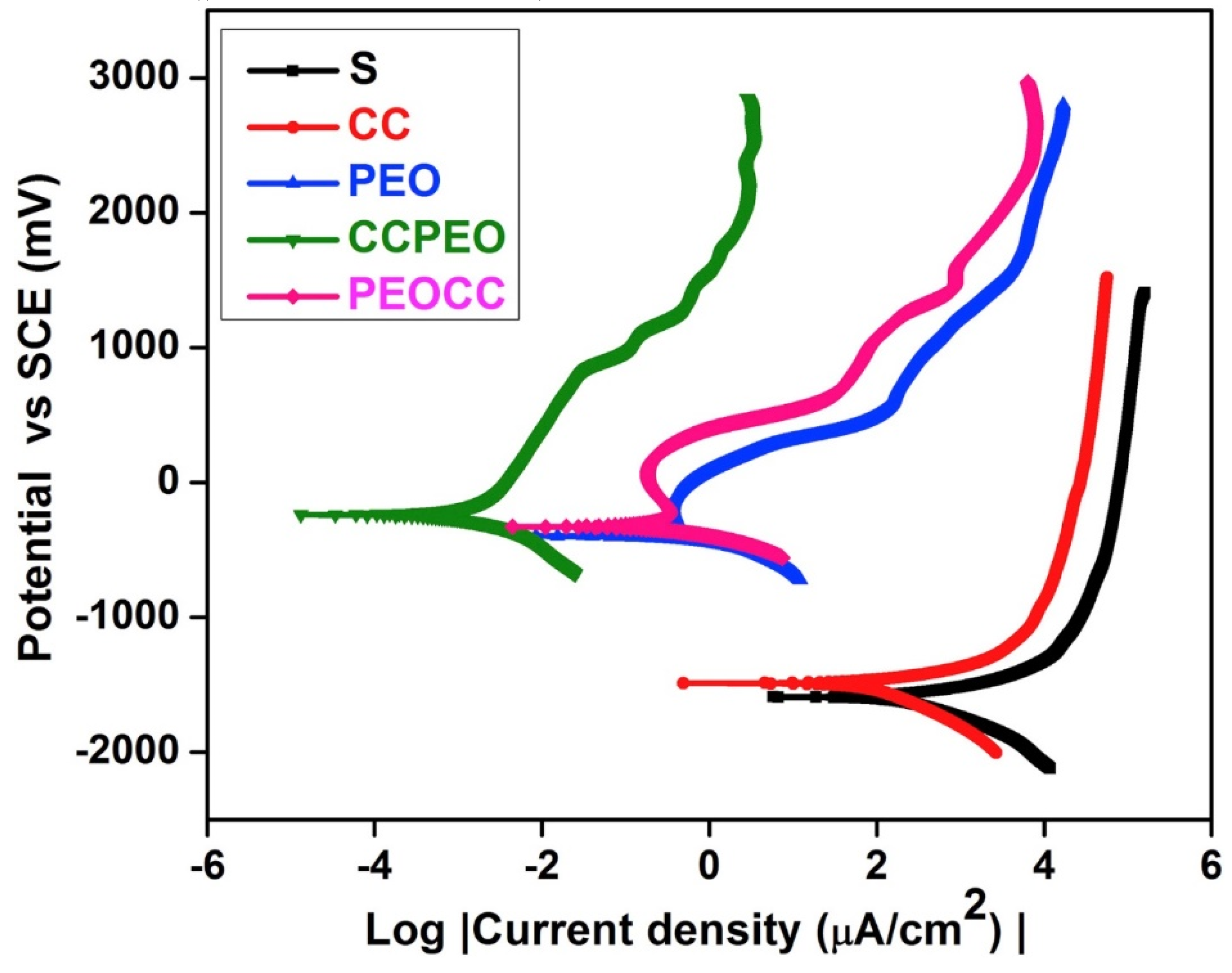
  50. Hariprasad, S.; Gowtham, S.; Arun, S.; Ashok, M.; Rameshbabu, N. Fabrication of duplex coatings on biodegradable AZ31 magnesium alloy by integrating cerium conversion (CC) and plasma electrolytic oxidation (PEO) processes. J. Alloys Compd. 2017, 722, 698–715. [Google Scholar] [CrossRef]
  51. Castano, C.E.; O’Keefe, M.J.; Fahrenholtz, W.G. Cerium-based oxide coatings. Curr. Opin. Solid State Mater. Sci. 2015, 19, 69–76. [Google Scholar] [CrossRef]
  52. Mu, S.; Du, J.; Jiang, H.; Li, W. Composition analysis and corrosion performance of a Mo–Ce conversion coating on AZ91 magnesium alloy. Surf. Coat. Technol. 2014, 254, 364–370. [Google Scholar] [CrossRef]
  53. Ng, W.F.; Wong, M.; Cheng, F. Cerium-based coating for enhancing the corrosion resistance of bio-degradable Mg implants. Mater. Chem. Phys. 2010, 119, 384–388. [Google Scholar] [CrossRef]
  54. Chen, Q.; Jiang, Z.; Tang, S.; Dong, W.; Tong, Q.; Li, W. Influence of graphene particles on the micro-arc oxidation behaviors of 6063 aluminum alloy and the coating properties. Appl. Surf. Sci. 2017, 423, 939–950. [Google Scholar] [CrossRef]
  55. Zhao, J.; Xie, X.; Zhang, C. Effect of the graphene oxide additive on the corrosion resistance of the plasma electrolytic oxidation coating of the AZ31 magnesium alloy. Corros. Sci. 2017, 114, 146–155. [Google Scholar] [CrossRef]
  56. Wen, C.; Zhan, X.; Huang, X.; Xu, F.; Luo, L.; Xia, C. Characterization and corrosion properties of hydroxyapatite/graphene oxide bio-composite coating on magnesium alloy by one-step micro-arc oxidation method. Surf. Coat. Technol. 2017, 317, 125–133. [Google Scholar] [CrossRef]
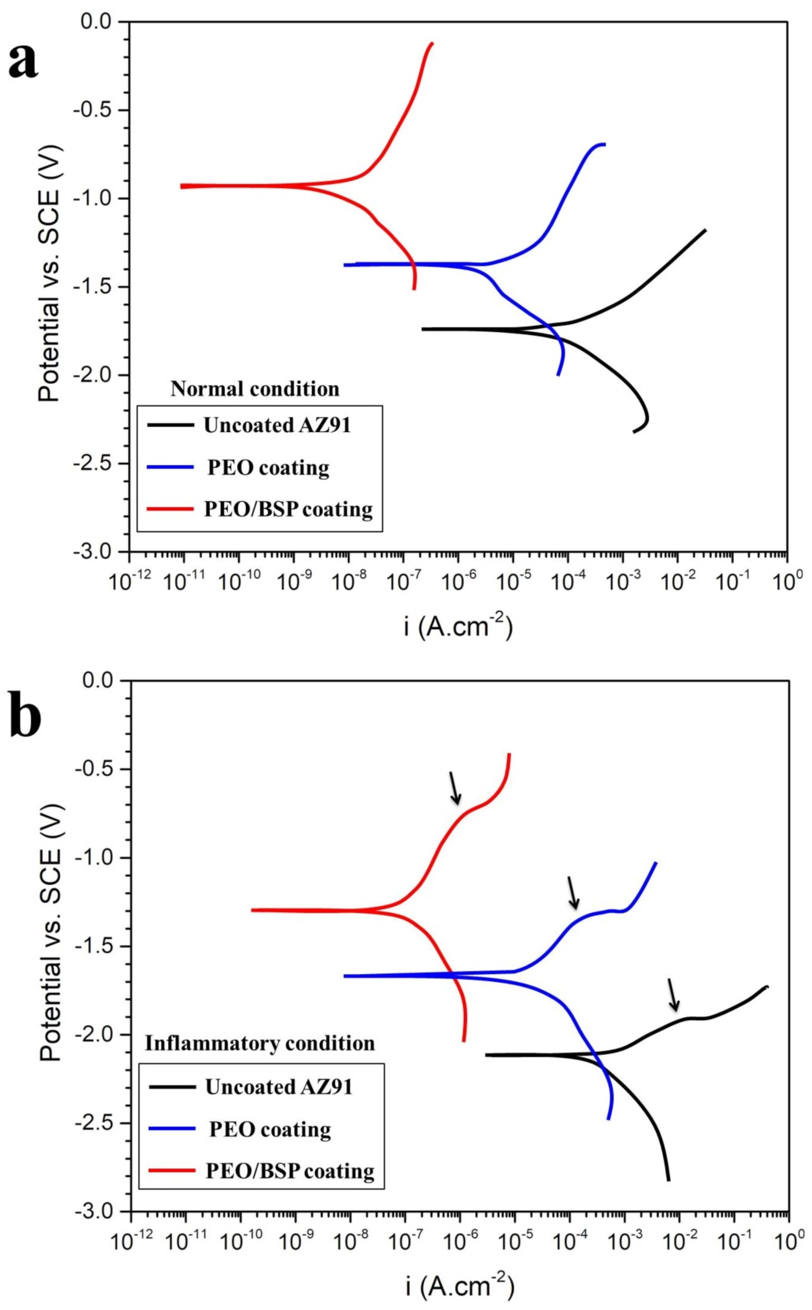
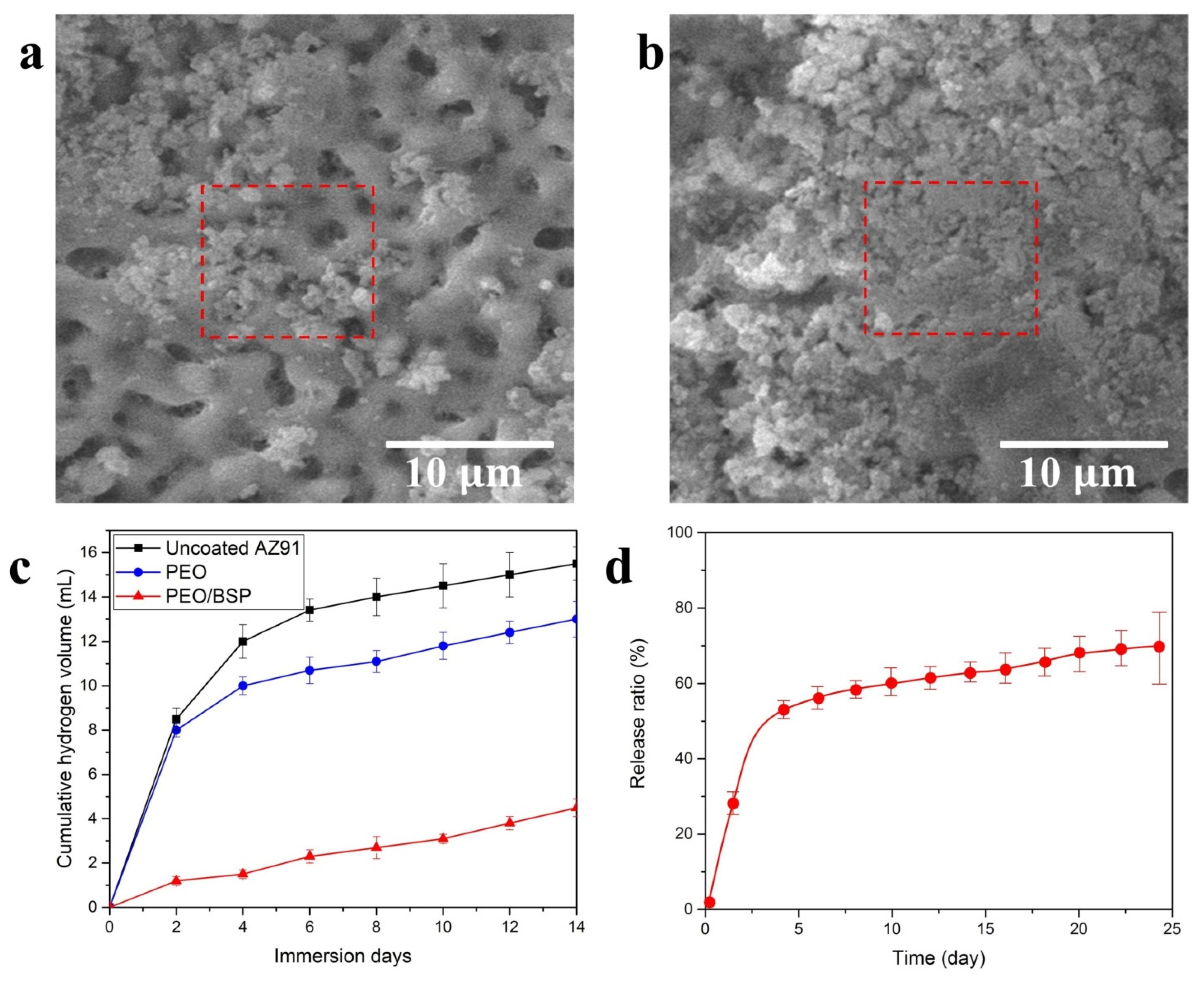
  57. Bordbar-Khiabani, A.; Yarmand, B.; Sharifi-Asl, S.; Mozafari, M. Improved corrosion performance of biodegradable magnesium in simulated inflammatory condition via drug-loaded plasma electrolytic oxidation coatings. Mater. Chem. Phys. 2020, 239, 122003. [Google Scholar] [CrossRef]
  58. Singh, S. Principles of Regenerative Medicine. Ann. Biomed. Eng. 2009, 2658–2659. [Google Scholar] [CrossRef]
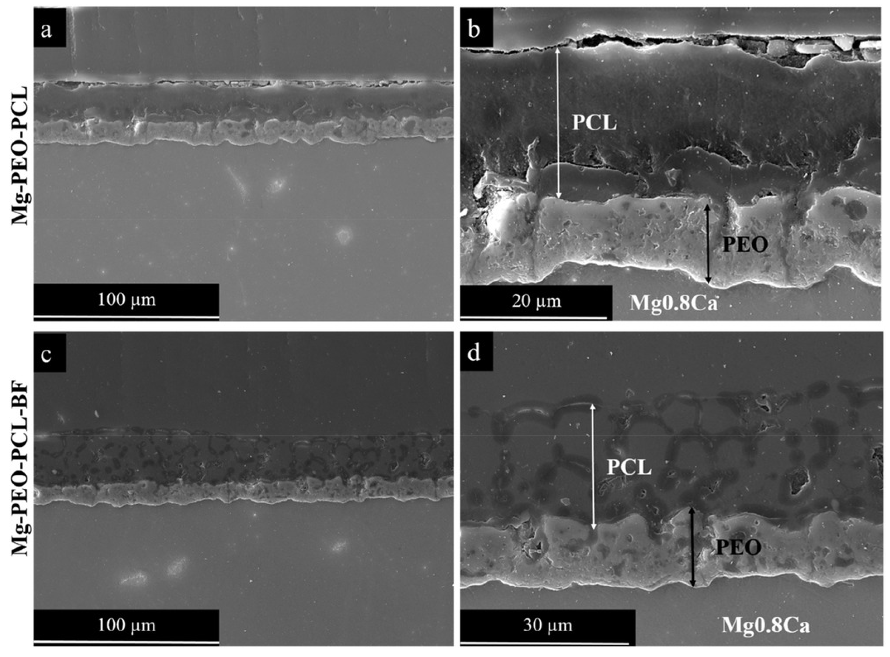
  59. Santos-Coquillat, A.; Martínez-Campos, E.; Vargas-Alfredo, N.; Arrabal, R.; Rodríguez-Hernández, J.; Matykina, E. Hierarchical Functionalized Polymeric-Ceramic Coatings on Mg-Ca Alloys for Biodegradable Implant Applications. Macromol. Biosci. 2019, 19, 1900179. [Google Scholar] [CrossRef] [PubMed]
  60. Calejo, M.T.; Ilmarinen, T.; Skottman, H.; Kellomäki, M. Breath figures in tissue engineering and drug delivery: State-of-the-art and future perspectives. Acta Biomater. 2018, 66, 44–66. [Google Scholar] [CrossRef] [PubMed]
  61. Agarwal, S.; Curtin, J.; Duffy, B.; Jaiswal, S. Biodegradable magnesium alloys for orthopaedic applications: A review on corrosion, biocompatibility and surface modifications. Mater. Sci. Eng. C 2016, 68, 948–963. [Google Scholar] [CrossRef] [Green Version]
  62. Hu, J.; Zhang, C.; Cui, B.; Bai, K.; Guan, S.; Wang, L.; Zhu, S. In vitro degradation of AZ31 magnesium alloy coated with nano TiO2 film by sol–gel method. Appl. Surf. Sci. 2011, 257, 8772–8777. [Google Scholar] [CrossRef]
  63. Rojaee, R.; Fathi, M.; Raeissi, K. Controlling the degradation rate of AZ91 magnesium alloy via sol–gel derived nanostructured hydroxyapatite coating. Mater. Sci. Eng. C 2013, 33, 3817–3825. [Google Scholar] [CrossRef]
  64. Zhang, Y.; Bai, K.; Fu, Z.; Zhang, C.; Zhou, H.; Wang, L.; Zhu, S.; Guan, S.; Li, D.; Hu, J. Composite coating prepared by micro-arc oxidation followed by sol–gel process and in vitro degradation properties. Appl. Surf. Sci. 2012, 258, 2939–2943. [Google Scholar] [CrossRef]
  65. Wang, S.; Wen, S.; Shen, M.; Guo, R.; Cao, X.; Wang, J.; Shi, X. Aminopropyltriethoxysilane-mediated surface functionalization of hydroxyapatite nanoparticles: Synthesis, characterization, and in vitro toxicity assay. Int. J. Nanomed. 2011, 6, 3449–3459. [Google Scholar] [CrossRef] [Green Version]
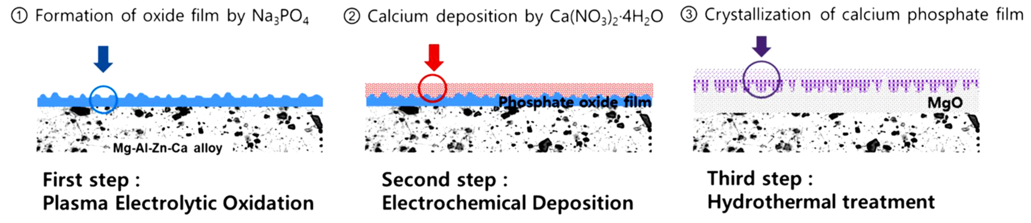
  66. Kim, Y.K.; Jang, Y.S.; Lee, Y.H.; Yi, H.K.; Bae, T.S.; Lee, M.H. Effect of Ca-P compound formed by hydrothermal treatment on biodegradation and biocompatibility of Mg-3Al-1Zn-1.5Ca alloy; in vitro and in vivo evaluation. Sci. Rep. 2017, 7, 712. [Google Scholar] [CrossRef] [Green Version]
Figure 1. The number of published papers related to the magnesium applications in the biomedical field, in the last fifty years (source Scopus).
Metals 10 00907 g001
Figure 2. Schematic of the plasma electrolytic oxidation (PEO) apparatus. Xu et al. [33].
Metals 10 00907 g002
Figure 3. Schematic of a PEO treated sample, (a) surface, (b) structure and (c) layers in PEO coating. Barati Darband et al. [35].
Metals 10 00907 g003
Figure 4. Schematic representation of extended PEO layer growth on Mg alloy. Barati Darband et al. [35].
Metals 10 00907 g004
Figure 5. Schematic diagram of voltage-time relationship in typical PEO experiment using DC constant current mode. Dehnavi et al. [44].
Metals 10 00907 g005
Figure 6. Schematic of PEO phenomenological evolution by increasing voltage using DC constant current mode. Chang et al. [45].
Metals 10 00907 g006
Figure 7. Schematic of the direct (a) and pulsed current waveform (b,c). ton and toff are the periods during which the current is turned on and off, respectively.
Metals 10 00907 g007
Figure 8. Potentiodynamic polarization curves (A) and Nyquist plots from electrochemical impedance spectroscopy (EIS) (B) comparing bare Mg, PEO treated and PEO plus hyaluronic acid (HA) covered samples. Kim et al. [49]. Please note that the authors used HA to indicate hyaluronic acid.
Metals 10 00907 g008
Figure 9. Potentiodynamic polarization curves of samples made of AZ31 alloy, modified in several ways (see Table 1) obtained in 7.4 pH SBF medium and compare to the substrate “S”. Hariprasad et al. [50].
Metals 10 00907 g009
Figure 10. Potentiodynamic polarization curves for AZ91 Mg alloy sample, PEO and PEO/BSP coated specimens obtained in (a) normal and (b) inflammatory condition (see the text). Bordbar-Khiabani et al. [57].
Metals 10 00907 g010
Figure 11. FESEM images of the (a) PEO and (b) PEO/BSP coatings; (c) cumulative hydrogen evolution of coatings after 14 days immersion in SBF and (d) the release ratio of BSP films on porous PEO coatings for 24 days. Bordbar-Khiabani et al. [57].
Metals 10 00907 g011
Figure 12. Cross-sectional backscattered electron micrographs of PEO/PCL compact layer (a,b) and PEO-PCL-BF porous coatings (c,d) formed on Mg0.8Ca alloy. Santos-Coquillat et al. [59].
Metals 10 00907 g012
Figure 13. SEM micrographs of C2C12-GFP cells after 96 h growing over PEO-PCL-BF layer. (a) monolayer formed over the hybrid material; (bd) magnifications of cells growing inside the formed pores. Santos-Coquillat et al. [59].
Metals 10 00907 g013
Figure 14. Electrochemical characterization of the PEO/sol-gel coated samples at different HA/β-TCP weight ratios and coating layers: (a) HA/β-TCP is 25/75, (b) HA/β-TCP is 50/50, (c) HA/β-TCP is 75/25, and (d) the three composition ratios coated with 15 sol-gel layers. Ibrahim et al. [48].
Metals 10 00907 g014
Figure 15. Schematic of the development of a bioactive coating on Mg-3Al-1Zn-1.5Ca alloy via multistep surface treatment of the substrate. Kim et al. [66].
Metals 10 00907 g015
Table 1. The identification codes for the CC, PEO, CCPEO and PEOCC samples with their respective electrolyte composition, pH, conductivity and the characteristic voltages for PEO and CCPEO coatings during the PEO process. Hariprasad et al. [50].
Sl.NoSample CodeElectrolyte CompositionpHk (mS/cm)Vb (±2 V)Vf (±2 V)Process Time (min)
1CC10 g/L Ce(NO3)3·6H2O + 2 mL/L H2O238.3240
2PEO7 g/L Na2SiO3·10H2O + 3 g/L KOH12.41824551215
3CCPEO10 g/L Ce(NO3)3·6H2O + 2 mL/L H2O2;38.3240
7 g/L Na2SiO3·10H2O + 3 g/L KOH12.41822050215
4PEOCC7 g/L Na2SiO3·10H2O + 3 g/L KOH;12.41824551215
10 g/L Ce(NO3)3·6H2O + 2 mL/L H2O238.3240

