Abstract
Due to their high specific strength, magnesium alloys are promising materials for further lightweighting in mobility applications. In contrast to casting and forming processes, additive manufacturing methods allow high degrees of geometrical freedom and can generate significant weight reductions due to load-specific part design. In wire arc additive manufacturing processes, large parts can be produced with high material utilization. Process-inherent high melt temperatures and solidification rates allow for the use of magnesium alloys which are otherwise complicated to process; this enables the use of unconventional alloying systems. Here, we report the development of a Mg-Al-Zn-Ca-rare earth alloy for wire arc additive manufacturing (WAAM). Compared to parts made of commercially available filler wire, the newly developed alloy achieves a higher strength (approx. +9 MPa yield strength, +25 MPa ultimate tensile strength) in WAAM.
1. Introduction
Magnesium is the lightest construction metal available and used mainly in the form of cast components. It can be processed in a wide variety of casting processes including gravity casting, low- and high pressure die casting, and thixomolding [1]. Compared to casting, additive layer manufacturing (ALM) allows for higher part complexity at the cost of reduced productivity. This enables further potential for weight savings in part design [2,3]. For Mg, two directions of ALM processes have been proven to be feasible: powder-based and wire-based methods. While powder-based additive manufacturing of Mg is already in use to produce high quality parts for medical applications [4], widespread use is prevented by the complex production process and slow building rates. Mg powder tends to oxidize fast, so the use of a chamber with controlled gas shielding is mandatory, limiting the maximum part size [5]. In selective laser melting (SLM), the vaporizing metal reduces the visibility in the chamber and, therefore, the laser efficiency, which further reduces processability [6,7].
Very good mechanical properties can be achieved using Mg additive manufacturing processes. Typically, SLM Mg parts show similar or even superior strength compared to cast and wrought parts due to the small volume melt pools where rapid solidification rates and short segregation paths are achieved [8,9].
Tandon et al. reported the mechanical values of direct energy deposited (DED) as well as powder bed fusioned MAP + 43 alloy powders in the “HIPed” (hot isostatic pressed) and subsequently T6 treated condition [10]. For the DED material, they achieved a yield strength (YS) of 170 MPa, an ultimate tensile strength (UTS) of 245 MPa, and an elongation of 6.4%. In contrast, the hot isostatic pressing led to an essentially pore-free material, which showed superior strength and ductility in T6 condition: 194 MPa YS, 312 MPa UTS, and elongation of up to 14%.
Wire-based processes (e.g., wire arc additive manufacturing—WAAM) have the advantage of easier and safer handling of filler metal compared to powder-based processes because commercial, state-of-the-art wire arc welding equipment can be used. Due to the existence of a local gas shielding provided by the welding gun, working inside a chamber is not necessary. Thus, there are practically no limitations in part size. Mg wire arc additive manufacturing offers the ability to produce large components with a high material efficiency without the need to handle powders or large quantities of molten magnesium.
Despite their advantages, wire-based processes for magnesium are relatively uncommon to date, not least due to insufficient filler wire availability. Only a limited number of filler wire grades are known, namely AZ31B, AZ61A, AZ91D, EZ33A, AZ101A, QE22A, AM50A, and AZ92A [11,12,13,14] and not all of them are commercially available at the moment. These grades are generally used as all-purpose wires for magnesium welding, where the filler wire is selected to best fit the base material composition. As these alloys are not specifically designed for welding or additive layer manufacturing purposes, their performance is limited.
To date, the number of published results of Mg WAAM is very small. To the best of our knowledge, no results for WAAM of Mg alloys were published yet using other than the before-mentioned standard alloys. Guo et al. reported WAAM of AZ31 wires and achieved 104 MPa YS, 263 MPa UTS, and elongation of 23% by adjusting the pulse frequency during processing [15]. Takagi et al. reported in [16] the wire arc additive manufacturing of bulk samples using AZ31 wires and varying processing conditions. They report a very low porosity of 2.5 × 10⁻⁴% in the central part of the object with the biggest defect being 7.74 × 10⁻⁴ mm3. The mechanical properties achieved are 95 MPa YS, 239 MPa UTS, and an elongation of 21% in the WAAM part, which is comparable to the values reported by Guo et al. in [15]. Holguin et al. and Han et al. reported WAAM of AZ91 alloy, showed microstructures and XRD-analysis but did not report mechanical properties [17,18]. Graf et al. used numerical approaches for predicting temperature fields of WAAM processes using AZ31 filler wire [19].
Additive manufacturing of magnesium parts is especially promising for applications where minimum weight and high specific strength are crucial, like aeronautics and space applications. However, magnesium parts must possess good flame resistance to achieve a certification. Tests carried out by the Federal Aviation Administration (FAA) showed that typical Mg-Al alloys are not able to fulfill these requirements while alloys including high amounts of rare earth elements (e.g., WE43 using around 4 wt.% of Y and 3 wt.% of rare earths or Elektron 21 using around 2.6 wt.% Nd and 1.3 wt.% Gd) [20,21] or minor amounts of Ca (AZ80 + 0.3 wt.% Ca and 0.35 wt.% Y) [22] are able to successfully pass the tests. We have previously shown that Mg-Al-Zn alloys using Ca as flame retardant can be used for welding magnesium sheets [23].
High specific strength values can be achieved using the WAAM process, as the fast solidification speeds lead to solid solution strengthening which also allows for subsequent precipitation hardening. Therefore, Mg alloys with high Al contents and additional strengthening phase forming elements are suitable candidates for generating high strength WAAM parts. A promising strategy is the addition of rare earth elements which have been shown to increase the strength of Mg-Al alloys due to the formation of intermetallic phases of the type Mg12RE, Al2RE, Al3RE and Al11RE3 [24,25]. This approach was followed in this study.
The novel alloy reported here—AEX11—is based on the casting alloys AZ91 (Mg-Al9-Zn1) and AZ61A (Mg-Al6-Zn1). Compared to these alloys, it has an increased Al content as well as minor additions of Ca and rare earth elements (Ce-rich mischmetal). The Al-content was chosen based on CALPHAD-calculations to match the amount of Mg17Al12 compared to AZ91 after the formation of Al-RE- and Al-Ca-phases (Figure 5). This allows the use heat treatment times and temperatures analogous to the ones used for AZ91. Ca was chosen to increase the flame resistance of the alloy and rare earth elements to increase the strength. Cerium-rich mischmetal (65 wt.% Ce, 35 wt.% La) was used due to its low price compared to single rare earth elements. Mechanical properties were evaluated from thin walled structures made from AZ61A and from plates (walls) made from AEX11, both produced via WAAM.
2. Materials and Methods
We produced AEX11 wire via casting and subsequent direct extrusion at LKR in Ranshofen, Austria, as described below. The nominal chemical compositions are given in Table 1 along with the compositions of AZ61A and AZ91D for comparison.

Table 1.
Nominal compositions of the alloys AZ61A (acc. to ASTM B107), AZ91D (acc. to ASTM B94), and AEX11.
AEX11 was prepared in a resistance heated furnace Nabertherm Liquitherm® (Nabertherm GmbH, Lilienthal, Germany) T20/H in a mild steel crucible with a melt capacity of 30 kg. The melt was covered with Ar + 1% SF6 shielding gas during preparation and casting. Casting temperature was 720 °C.
The alloy was gravity cast into billets with a diameter of 65 mm and a height of 240 mm in a tempered (150 °C) mild steel mold. The billets were turned to a diameter of 58.5 mm and a length of 180 mm and homogenized at 420 °C for 8 h with subsequent cooling using forced air resulting in a cooling rate of approximately 25 K/min. Afterwards, the billets were extruded in two single steps to the desired filler wire diameter (Φ58.5 mm → Φ19.5 mm → Φ1.2 mm) using a 1.5 MN direct extrusion press NEHP 1500.01 manufactured by Müller Engineering, Todtenweis, Germany. A more detailed explanation of the wire manufacturing process can be found elsewhere [17].
Directly before welding, the wires were cleaned using isopropanol and a fiber mat. Wire arc additive manufacturing of AEX11 was carried out using the gas-metal arc-welding cold metal transfer (CMT) process (Fronius, Pettenbach, Austria). The power source was a Fronius CMT TPS with the following parameters: welding curve KL 1904, weld speed 12 mm/s, wire feed rate 3.5 m/min (base layer) and 2.2 m/min (building layers), current 51 A, pulse frequency 80–120 Hz, layer thickness 2.5 mm each, and a wall thickness of 5 mm. The distance between workpiece and tip was 13 mm. Ar with 30% He was used as shielding gas. The nozzle diameter was 14 mm and the gas flow was 14 L/min. Figure 1 shows the AM welding facility at LKR.
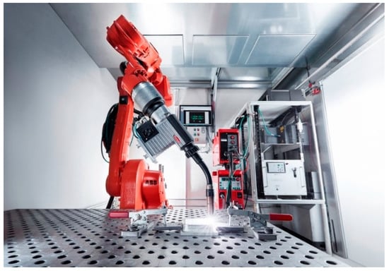
Figure 1.
Additive manufacturing lab at LKR, Ranshofen.
Thin-walled structures with a height of 80 mm, a length of 130 mm and a width of 30 mm were manufactured continuously from AZ61 wires on a AZ31 base plate (Mg-3.0Al-0.6Zn). Walls with dimensions of 140 mm × 120 mm × 5 mm were manufactured discontinuously (layer for layer) using AEX11 wires for microstructural and mechanical investigations. In the plates, the welding direction was alternating and changed every single layer. The walls of AEX11 manufactured via WAAM are intended to represent a section of the structures manufactured out of AZ61A. The AZ61 samples were obtained from AZ61A filler wires sourced from DRATEC Drahttechnik GmbH, Krefeld, Germany. The resulting structures can be seen in Figure 2.
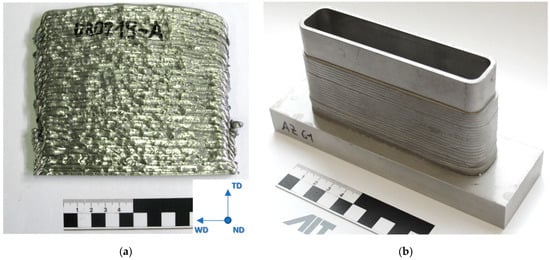
Figure 2.
Additive manufactured plate (a) out of AEX11 with schematic representation of sample extraction. The red area indicates the position of samples for microstructural and EBSD analysis. Additive manufactured sample structure out of AZ61A (b). The power source was a Fronius CMT TPS with the following parameters: weld speed 12 mm/s, wire feed rate 3.5 m/min (base layer) and 2.2 m/min (building layers), current 51 A, layer thickness 2.5 mm each, and a wall thickness of 5 mm.
After milling off the wavy surface, tensile test specimens were taken out of the WAAM parts in welding direction (WD) and transversal direction (TD). The positions of specimen extraction are shown schematically in Figure 3 (all dimensions in mm), and the geometry of the specimens is shown in Figure 4. In the as fabricated state, five samples per direction were taken and, in the T6 condition, four samples per direction were taken. Only one sample per direction was taken for analyzing the solution heat treatment state. Tensile tests were carried out at room temperature using a DIL 805 A/D deformation dilatometer (Bähr Thermoanalyse GmbH, Hüllhorst, Germany) at a deformation rate of 0.006 s−1.
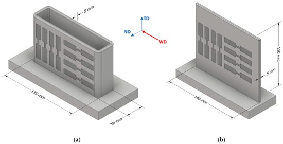
Figure 3.
Schematic position of specimen extraction for AZ61A (a) and AEX11 (b). Specimens were extracted in welding direction (WD) and transversal direction (TD). The walls of AEX11 manufactured via WAAM represent a section of the structures manufactured out of AZ61A.
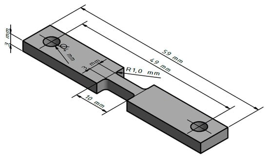
Figure 4.
Dimensions of tensile test specimen.
For solution heat treatment, some of the tensile specimens were placed in a preheated furnace (415 °C) for 6 h and then heated up to 430 °C with holding for another 6 h, followed by water quenching. Afterwards, the solution heat treated samples were placed in a preheated furnace (260 °C) for 30 min with subsequent water quenching.
Thermodynamic calculations were done using Thermo-Calc software (Version 2017a) and database TCMG5 (both Thermo-Calc Software AB, Solna, Sweden).
The samples for microstructural investigations were extracted from the WAAM parts (Figure 3) perpendicular to all three directions (WD welding direction, ND normal direction and TD transversal direction) from at least 30 mm distance to the base plate. The samples were mechanically polished to ¼ µm and then finished using colloidal silica suspension. Additionally, selected samples were etched using picric acid to visualize the grain boundaries and allows for investigating the grain structure.
Microstructural investigations in all directions were carried out using optical light microscopy and scanning electron microscopy (SEM). A Tescan MIRA3 field emission gun (FEG) scanning electron microscope (Brno, Czech Republic) operated at 15 kV and a 4-quadrant solid-state backscattered electron (BSE) detector were used for imaging and energy dispersive X-ray spectroscopy (EDS) with an EDAX (Mahwah, NJ, USA) Octane Elect silicon drift detector system. Electron backscattered diffraction (EBSD) was performed at 20 kV and a working distance of ~7 mm on a Zeiss Sigma 500 VP FEG scanning electron microscope (AZ61A) (Carl Zeiss AG, Oberkochen, Germany) and at ~15 mm working distance on the aforementioned Tescan Mira 3 (AEX11). On both microscopes, an EDAX Hikari Plus EBSD camera (AMETEK, Berwyn, PA, USA) was used. EBSD data analysis was carried out with EDAX OIM 8 (AMETEK, Berwyn, PA, USA). The samples were taken about 30 mm away from the base plate. For cleanup, we used of grain dilatation with a grain tolerance angle of 5° and a minimum grain size of 2 px (AZ61A) or 20 px (AEX11). For grain size analysis, a misorientation angle of 15° was used to determine grain boundaries.
3. Results and Discussion
Figure 5 shows the results of the equilibrium thermodynamic calculations carried out for AZ61A, AZ91D, and AEX11 alloys. According to the calculations, the amount of the intermetallic phase Mg17Al12 is predicted to be significantly higher in the alloy AEX11 than in AZ61A, whilst, for AZ91D, it is approximately equal as in AEX11. Additionally, the alloy AEX11 shows small amounts of intermetallic phases Al11RE3 and Al2Ca. While the Mg17Al12 in the divorced eutectic can be completely dissolved into the matrix by solution heat treatment, the Al-RE and Al2Ca phases cannot.
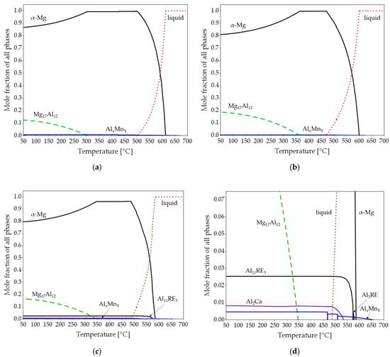
Figure 5.
Equilibrium thermodynamic calculations of AZ61A (a), AZ91D (b) and AEX11 (c,d). (d) represents a section of (c).
As the manganese content is about equal in all three alloys, the resulting AlxMny phases are almost identical with regard to their stoichiometry depending on the relative Al and Mn amounts present. The calculated total amount of intermetallic phases is highest for AEX11 because it contains the highest amount of alloying elements. The calculated solidification ranges are 116 °C for AZ61A, 124 °C for AEX11, and 136 °C for AZ91D.
Figure 6 shows SEM of the microstructure of AEX11 fabricated via WAAM in the “as fabricated” and the “T6 heat treated” states as well as the microstructure of AZ61A in the “as fabricated” state. EDS measurements identify the present intermetallic phases as Al-RE, Al-Ca, and Mg/Al-rich phases. With reference to the thermodynamic calculations and literature [24,26,27], these are presumed to be Al11RE3, Al2Ca, and β-Mg17Al12. By indexing of EBSD patterns, the Al-RE phases were identified with high confidence as orthorhombic Al11RE3 phase with large d-spacings (a = 4.4 Å, b = 10.1 Å, c = 13.0 Å).
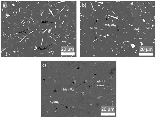
Figure 6.
Microstructure of parts manufactured via WAAM. (a) AEX11 “as fabricated” state; (b) AEX11 after T6 heat treatment; (c) AZ61A “as fabricated”; (backscattered SEM).
Due to the higher cooling rates of WAAM compared to classical casting processes (with the exception of high pressure die casting), typical grain sizes and phase fractions of coarsely precipitated (divorced) Mg17Al12 are lower, resulting in generally higher mechanical properties [28,29,30]. The Al11RE3 intermetallic phases found in the AEX11 are relatively large and needle-like; therefore, their contribution to strengthening is not clear. In [31], it is stated that the addition of RE increases the strength of Mg-Al. Nevertheless, it is also shown that, with an increasing amount of RE, the size of Al-RE phases increases, leading to a decrease of mechanical properties. Additionally, a positive contribution to creep resistance is expected due to the high thermal stability of the phases [32,33]. Figure 6b shows that the T6 heat treatment resulted in spheroidization of Mg17Al12 phases, while no change can be detected in the Al-RE phases. This is also consistent with the thermodynamic calculation (Figure 5c,d), which shows that the phase dissolution temperature of Al-RE is significantly higher than the heat treatment temperature, while the Mg17Al12 is dissolved and precipitated in the T6 heat treatment.
While in wrought material the grains are deformed and often partially recrystallized, WAAM material typically possesses columnar grains in the welding direction and a low grain size compared to conventional casting methods resulting from the low amount of molten volume and high solidification rates. The resulting grain structure is mainly dependent on the component geometry and the energy input during processing, which is dependent on the wire feed, the wire thickness, power settings, and polarity. Additionally, the grain sizes are strongly dependent on the cooling rate. Therefore, the grain size can be minimized using optimized processing parameters [34]. Guo et al. [15] have achieved grain sizes of 20–39 µm while the AZ61A shown in this work has a grain size of 31 ± 12 µm and the grain size of AEX11 is roughly 55 ± 19 µm. The grain size was determined via EBSD (Figure 7). No formation of columnar grains was observed and the grains were formed approximately equiaxially.
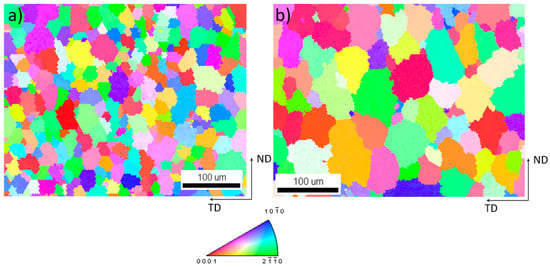
Figure 7.
Detail of inverse pole figure [001] map of (a) AZ61A and (b) AEX11; (cross section in welding direction; TD: transversal direction; ND: normal direction).
Figure 8 gives a comparison of the microstructure of AEX11 (Figure 8a,b) and AZ61A (Figure 8c,d) in the “as fabricated” state, manufactured via WAAM. In agreement with SEM, potential Al-Mn (dark grey) and Mg17Al12 (light grey) can be found. In AZ61A, potential Al-Mn is the dominating phase while potential Mg17Al12 is only visible in very small quantities, coming from the high cooling speed during processing. Al has a high solubility limit in Mg and the formation of Mg17Al12 can be suppressed when the solidification speed is fast enough. This is in agreement with the thermodynamic calculations which show that the phase is only stable at temperatures below 300 °C for AZ61A and 350 °C for AEX11. Due to the higher amount of Al in AEX11, the amount of already precipitated potential Mg17Al12 is substantially higher. Additionally, needle shaped Al-RE phases are present in AEX11. According to the thermodynamic calculations, their temperature of formation is above the solidus temperature. Thus, achieving a complete solution of these phases via heat treatment is not possible.
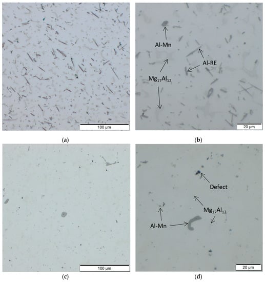
Figure 8.
Microstructures of AEX11 (a,b) and AZ61A (c,d) in the “as fabricated” state, manufactured via WAAM.
A number of small defects (pores, cavities) were found in the samples. The pores have a size of <20 µm and are distributed evenly across the cross section of the samples. It is believed that the pores are mainly a result of impurities in the filler wires and defects in the surface region of underlying layers [35]. As the process was carried out only using local gas shielding instead of a gas chamber, insufficient shielding might have led to porosity [36]. The cavities occur preferably in transitions between layers (Figure 9). Possibly, a reduction of porosity could be achieved by further adaptions of processing parameters and proper preparation (cleaning) of base material and filler wires in future research. A better indication of the quantity and size of the voids to take targeted measures could be provided by a non-destructive in-line analysis method such as that presented by Javadi et al. [37].
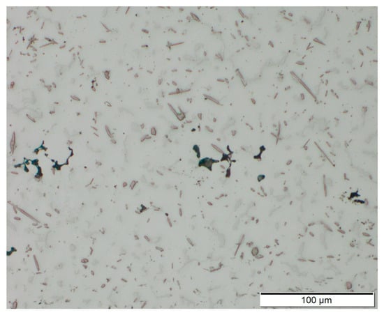
Figure 9.
Cross section of AEX11 sample manufactured via WAAM. Voids occur in the transitions between single layers.
Tensile test results of WAAM magnesium parts are given in Figure 10 and Table 2. In the “as fabricated” state, AEX11 has an elongation at break of around 6% while AZ61A achieved values of around 16%. The amount of Mg17Al12 in AEX11 is about equal to the amount of what one would expect to find in AZ91D; therefore, a T6 heat treatment can be performed with approximately the same efficiency. A relatively high annealing temperature was chosen to keep the treatment time low. Nevertheless, reducing this temperature may lead to even higher strength at the cost of increased treatment time.
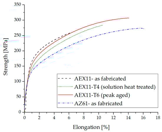
Figure 10.
Typical tensile test results of additive manufactured structures out of AZ61 and AEX11 filler wires.
Table 2.
Mechanical properties (tensile) of AZ61A and AEX11 in detail.
After dissolution of Mg17Al12, high elongation was achieved while at the same time the strength was decreased. Annealing at 260 °C was carried out to exploit the precipitation strengthening effect of Mg17Al12. We achieved a maximum UTS of 307 MPa at an elongation of 14% using the alloy AEX11, designed specifically for WAAM processing in the T6 state. With a density of ~1.84 g/cm³, this results in a specific strength of ~166.8 Nms−1, which is comparable to the aluminum alloy Al-2024-T6 (171.5 Nms−1) but inferior to Al-7075-T6 forgings (196.4 Nms−1) [38]. The UTS is 15% higher than that of parts made from our reference material, commercial AZ61A wires in the as fabricated state, using classical welding parameters without frequency modulation. The strength of the baseline material is comparable to previous reports [15].
The elongation of the AEX11 samples increased after every single heat treatment step. This can be attributed to the spheroidization of brittle phases (mainly Mg17Al12). In AZ61A, the amount of precipitated β-Mg17Al12 is inherently lower, leading to a good deformability already in the as fabricated state. It is known that β-Mg17Al12 has a detrimental effect on the ductility of Mg-Al alloys [11,39]. In the WAAM AZ61A samples, a large proportion of Al was found to be already in solid solution due to the rapid solidification as only a small amount of Al-rich phases was found in the microstructural analysis. Additionally, according to [40,41], hardness increase by heat treatment is not very effective for AZ61A. Therefore, no further heat treatment was applied.
The mechanical properties of the WAAM manufactured parts shown in this work can be compared to the ones achieved in wrought processes such as forging [42] and extrusion [43]. Forged AZ61 parts reach an ultimate tensile strength of 295 MPa and an elongation of 12% [44], while, for extruded AZ61, UTS values of 310 MPa at elongations of 16% are stated [45].
Figure 11 shows the fracture surface of a tensile test specimen of AEX11 in the as fabricated state. The matrix deforms around the intermetallic phases before detaching. All samples showed ductile fracture behavior because no continuous network of intermetallic phases is formed on the grain boundaries, which could act as crack propagation sites.
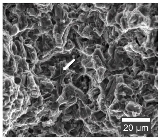
Figure 11.
Fracture surface of AEX11 tensile test specimen in the as fabricated state (secondary electron SEM). Al-RE phase indicated with an arrow.
4. Conclusions
WAAM is a suitable production process for low quantity Mg parts and prototypes. Especially for large dimensional parts, this processing route can be faster and easier to implement than traditional routes like milling and casting.
In this research, we showed that commercial AZ61 filler wire as well as custom made wire from AEX11 can be used for the fabrication of WAAM parts. We demonstrated that new alloys with a high proportion of soluble elements can be used to take advantage of the high cooling rate of the process and, thus, achieve superior mechanical properties.
While WAAM can be used to produce components with attractive properties, there are still some challenges along the process chain to be solved. For wire manufacturing, impurities must be reduced to a minimum as these may lead to porosity in the parts. For WAAM itself, temperature control and optimization of the welding path are essential to avoid warpage.
Author Contributions
This paper is the work of several authors, the individual contributions are subsequently listed: conceptualization, S.G., J.A.Ö., and M.F.; methodology, S.G. and J.A.Ö.; software, S.G.; validation, J.A.Ö.; formal analysis, J.A.Ö. and M.F.; investigation, S.G., J.A.Ö., A.R.A., and A.B.; data curation, S.G.; writing—original draft preparation, S.G. and J.A.Ö.; writing—review and editing, S.G., J.A.Ö., A.R.A., A.B., and M.F.; visualization, S.G.; supervision, J.A.Ö. and M.F.; project administration, S.G. All authors have read and agreed to the published version of the manuscript.
Funding
This research was funded by the European Regional Development Fund (EFRE) in the framework of the EU-program “IWB Investition in Wachstum und Beschäftigung Österreich 2014–2020” and the federal state Upper Austria.
Acknowledgments
The authors thank Martin Schnall for his efforts in the search for suitable processing parameters and his support in the production of AM structures, Iris Baumgartner for the preparation of metallographic samples, and René de Kloe (EDAX/AMETEK) for providing crystallographic files for Al11RE3.
Conflicts of Interest
The authors declare no conflict of interest. The founding sponsors had no role in the design of the study; in the collection, analyzes, or interpretation of data; in the writing of the manuscript, or in the decision to publish the results.
References
- Mordike, B.L.; Ebert, T. Magnesium: Properties—Applications—Potential. Mater. Sci. Eng. A 2001, 302, 37–45. [Google Scholar] [CrossRef]
- Emmelmann, C.; Sander, P.; Kranz, J.; Wycisk, E. Laser Additive Manufacturing and Bionics: Redefining Lightweight Design. Phys. Procedia 2011, 12, 364–368. [Google Scholar] [CrossRef]
- Herzog, D.; Seyda, V.; Wycisk, E.; Emmelmann, C. Additive manufacturing of metals. Acta Mater. 2016, 117, 371–392. [Google Scholar] [CrossRef]
- Windhagen, H.; Radtke, K.; Weizbauer, A.; Diekmann, J.; Noll, Y.; Kreimeyer, U.; Schavan, R.; Stukenborg-Colsman, C.; Waizy, H. Biodegradable magnesium-based screw clinically equivalent to titanium screw in hallux valgus surgery: Short term results of the first prospective, randomized, controlled clinical pilot study. Biomed. Eng. OnLine 2013, 12, 62. [Google Scholar] [CrossRef]
- Gieseke, M.; Kiesow, T.; Noelke, C.; Kaierle, S.; Maier, H.J.; Matena, J.; Kampmann, A.; Nolte, I.; Gellrich, N.-C.; Haferkamp, H. Challenges of Processing Magnesium and Magnesium Alloys by Selective Laser Melting. In Proceedings of the World PM 2016 Congress and Exhibition. European Powder Metallurgy Association (EPMA), Hamburg, Germany, 9–13 October 2016. [Google Scholar]
- Jauer, L.; Meiners, W.; Vervoort, S.; Gayer, C.; Zumdick, N.A.; Zander, D. Selective Laser Melting of Magnesium Alloys. In Proceedings of the World Powder Metallurgy Conference 2016, Hamburg, Germany, 9–13 October 2016. [Google Scholar]
- Gieseke, M.; Noelke, C.; Kaierle, S.; Wesling, V.; Haferkamp, H. Selective Laser Melting of Magnesium and Magnesium Alloys. In Magnesium Technology 2013; Hort, N., Mathaudhu, S.N., Neelameggham, N.R., Alderman, M., Eds.; Springer International Publishing: Berlin/Heidelberg, Germany, 2016; pp. 65–68. ISBN 978-3-319-48150-0. [Google Scholar]
- Manakari, V.; Parande, G.; Gupta, M. Selective Laser Melting of Magnesium and Magnesium Alloy Powders: A Review. Metals 2017, 7, 2. [Google Scholar] [CrossRef]
- Frazier, W.E. Metal Additive Manufacturing: A Review. J. Mater. Eng. Perform. 2014, 23, 1917–1928. [Google Scholar] [CrossRef]
- Tandon, R.; Palmer, T.; Gieseke, M.; Noelke, C.; Kaierle, S. Additive manufacturing of magnesium alloy powders: Investigations into process development using elektron®MAP+43 via laser powder bed fusion and directed energy deposition. In Proceedings of the World PM 2016 Congress and Exhibition; European Powder Metallurgy Association (EPMA), Hamburg, Germany, 9–13 October 2016. [Google Scholar]
- Avedesian, M.M.; Baker, H. ASM Specialty Handbook: Magnesium and Magnesium Alloys; ASM International: Russel Township, OH, USA, 1999; ISBN 978-0-87170-657-7. [Google Scholar]
- Products–Mag Specialties. Available online: https://www.magspecialtiesinc.com/products/ (accessed on 10 July 2019).
- Magnesium Alloys|Products|Washington Alloy Company. Available online: https://weldingwire.com/products/Magnesium-Alloys (accessed on 10 July 2019).
- Magnesium-DRATEC. Available online: http://www.dratec.de/magnesium.html (accessed on 10 July 2019).
- Guo, J.; Zhou, Y.; Liu, C.; Wu, Q.; Chen, X.; Lu, J. Wire Arc Additive Manufacturing of AZ31 Magnesium Alloy: Grain Refinement by Adjusting Pulse Frequency. Materials 2016, 9, 823. [Google Scholar] [CrossRef]
- Takagi, H.; Sasahara, H.; Abe, T.; Sannomiya, H.; Nishiyama, S.; Ohta, S.; Nakamura, K. Material-property evaluation of magnesium alloys fabricated using wire-and-arc-based additive manufacturing. Addit. Manuf. 2018, 24, 498–507. [Google Scholar] [CrossRef]
- Han, S.; Zielewski, M.; Martinez Holguin, D.; Michel Parra, M.; Kim, N. Optimization of AZ91D Process and Corrosion Resistance Using Wire Arc Additive Manufacturing. Appl. Sci. 2018, 8, 1306. [Google Scholar] [CrossRef]
- Holguin, D.A.M.; Han, S.; Kim, N.P. Magnesium Alloy 3D Printing by Wire and Arc Additive Manufacturing (WAAM). MRS Adv. 2018, 3, 2959–2964. [Google Scholar] [CrossRef]
- Graf, M.; Hälsig, A.; Höfer, K.; Awiszus, B.; Mayr, P. Thermo-Mechanical Modelling of Wire-Arc Additive Manufacturing (WAAM) of Semi-Finished Products. Metals 2018, 8, 1009. [Google Scholar] [CrossRef]
- Marker, T. Evaluating the Flammability of Various Magnesium Alloys During Laboratory- and Full-Scale Aircraft Fire Test; US Department of Transportation, Federal Aviation Administration: Atlantic City, NJ, USA, 2013.
- Marker, T.R. Development of a Laboratory-Scale Flammability Test for Magnesium Alloys Used in Aircraft Seat Construction; Federal Aviation Administration: Washington, DC, USA, 2014.
- Gneiger, S.; Frank, S.; Betz, A. Untersuchung des Elementeinflusses von Ca und Y auf Magnesiumlegierungen. In Proceedings of the 9th Ranshofener Leichtmetalltage, Bad Ischl, Austria, 9–10 November 2016. [Google Scholar]
- Gneiger, S.; Gradinger, R.; Betz, A. Manufacturing route for producing tailor-made magnesium wires for welding and ALM purposes. In Proceedings of the 2017 World Magnesium Conference, Singapore, 21–23 May 2017. [Google Scholar]
- Bakke, P.; Westengen, H. The Role of Rare Earth Elements in Structure and Property Control of Magnesium Die Casting Alloys. In Essential Readings in Magnesium Technology; Springer: Berlin/Heidelberg, Germany, 2016; pp. 313–318. ISBN 978-3-319-48588-1. [Google Scholar]
- Rokhlin, L.L. Magnesium Alloys Containing Rare Earth Metals: Structure and Properties; CRC Press: Boca Raton, FL, USA, 2003; ISBN 978-0-429-17922-8. [Google Scholar]
- Li, P.; Tang, B.; Kandalova, E.G. Microstructure and properties of AZ91D alloy with Ca additions. Mater. Lett. 2005, 59, 671–675. [Google Scholar] [CrossRef]
- Nami, B.; Shabestari, S.G.; Razavi, H.; Mirdamadi, S.; Miresmaeili, S.M. Effect of Ca, RE elements and semi-solid processing on the microstructure and creep properties of AZ91 alloy. Mater. Sci. Eng. A 2011, 528, 1261–1267. [Google Scholar] [CrossRef]
- Dini, H.; Andersson, N.-E.; Jarfors, A. Effect of Mg17Al12 Fraction on Mechanical Properties of Mg-9%Al-1%Zn Cast Alloy. Metals 2016, 6, 251. [Google Scholar] [CrossRef]
- Cai, H.; Guo, F.; Su, J. Combined effects of cerium and cooling rate on microstructure and mechanical properties of AZ91 magnesium alloy. Mater. Res. Express 2018, 5, 016503. [Google Scholar] [CrossRef]
- Zhu, T.; Chen, Z.W.; Gao, W. Effect of cooling conditions during casting on fraction of β-Mg17Al12 in Mg–9Al–1Zn cast alloy. J. Alloys Compd. 2010, 501, 291–296. [Google Scholar] [CrossRef]
- Cui, X.; Liu, H.; Meng, J.; Zhang, D. Microstructure and mechanical properties of die-cast AZ91D magnesium alloy by Pr additions. Trans. Nonferrous Met. Soc. China 2010, 20, s435–s438. [Google Scholar] [CrossRef]
- Easton, M.; Zhu, S.; Gibson, M.; Abbott, T.; Ang, H.Q.; Chen, X.; Birbilis, N.; Savage, G. Performance Evaluation of High-Pressure Die-Cast Magnesium Alloys. In Magnesium Technology 2017; Solanki, K.N., Orlov, D., Singh, A., Neelameggham, N.R., Eds.; Springer International Publishing: Berlin/Heidelberg, Germany, 2017; pp. 123–129. ISBN 978-3-319-52391-0. [Google Scholar]
- Zhu, S.; Easton, M.A.; Abbott, T.B.; Nie, J.-F.; Dargusch, M.S.; Hort, N.; Gibson, M.A. Evaluation of Magnesium Die-Casting Alloys for Elevated Temperature Applications: Microstructure, Tensile Properties, and Creep Resistance. Metall. Mater. Trans. A 2015, 46, 3543–3554. [Google Scholar] [CrossRef]
- Klein, T.; Schnall, M. Control of macro-/microstructure and mechanical properties of a wire-arc additive manufactured aluminum alloy. Int. J. Adv. Manuf. Technol. 2020. [Google Scholar] [CrossRef]
- Monteiro, W.A. New Features on Magnesium Alloys; InTech: Rijeka, Croatia, 2012; ISBN 978-953-51-0668-5. [Google Scholar]
- Liu, L.; Song, G.; Liang, G.; Wang, J. Pore formation during hybrid laser-tungsten inert gas arc welding of magnesium alloy AZ31B—Mechanism and remedy. Mater. Sci. Eng. A 2005, 390, 76–80. [Google Scholar] [CrossRef]
- Javadi, Y.; MacLeod, C.N.; Pierce, S.G.; Gachagan, A.; Lines, D.; Mineo, C.; Ding, J.; Williams, S.; Vasilev, M.; Mohseni, E.; et al. Ultrasonic phased array inspection of a Wire + Arc Additive Manufactured (WAAM) sample with intentionally embedded defects. Addit. Manuf. 2019, 29, 100806. [Google Scholar] [CrossRef]
- Kaufman, J.G. Properties of Aluminum Alloys: Tensile, Creep, and Fatigue Data at High and Low Temperatures; ASM International: Russel Township, OH, USA, 1999; ISBN 978-0-87170-632-4. [Google Scholar]
- Kammer, C. Magnesium-Taschenbuch; Aluminium-Verlag: Düsseldorf, Germany, 2000; ISBN 978-3-87017-264-0. [Google Scholar]
- Jo, S.M.; Go, Y.; You, B.S.; Kim, Y.M. Precipitation Behavior of Mg–Al–Sn–Zn–(Na) Alloy. In Magnesium Technology 2017; Solanki, K.N., Orlov, D., Singh, A., Neelameggham, N.R., Eds.; Springer International Publishing: Berlin/Heidelberg, Germany, 2017; pp. 203–207. [Google Scholar]
- Manivannan, S.; Gopalakrishnan, S.K.; Saravana Murthy, L.N.; Babu, K.; Sundarrajan, S. Microstructure and Mechanical Properties of Cast Mg-6Al- 1Zn-xRE Alloy with Additions of Yttrium at Different Ageing Temperature. Eur. J. Sci. Res. 2014, 122, 381–391. [Google Scholar]
- Papenberg, N.P.; Gneiger, S.; Weißensteiner, I.; Uggowitzer, P.J.; Pogatscher, S. Mg-Alloys for Forging Applications—A Review. Materials 2020, 13, 985. [Google Scholar] [CrossRef] [PubMed]
- Gneiger, S.; Papenberg, N.; Frank, S.; Gradinger, R. Investigations on Microstructure and Mechanical Properties of Non-flammable Mg–Al–Zn–Ca–Y Alloys. In Proceedings of the Magnesium Technology 2018; Orlov, D., Joshi, V., Solanki, K.N., Neelameggham, N.R., Eds.; Springer International Publishing: Berlin/Heidelberg, Germany, 2018; pp. 105–113. [Google Scholar]
- ASM Handbook Volume 2: Properties and Selection: Nonferrous Alloys and Special-Purpose Materials-ASM International. Available online: https://www.asminternational.org/materials-resources/results/-/journal_content/56/10192/06182G/PUBLICATION (accessed on 24 September 2019).
- Zeng, Z.; Stanford, N.; Davies, C.H.J.; Nie, J.-F.; Birbilis, N. Magnesium extrusion alloys: A review of developments and prospects. Int. Mater. Rev. 2019, 64, 27–62. [Google Scholar] [CrossRef]


© 2020 by the authors. Licensee MDPI, Basel, Switzerland. This article is an open access article distributed under the terms and conditions of the Creative Commons Attribution (CC BY) license (http://creativecommons.org/licenses/by/4.0/).