Article

High Nb–TiAl Intermetallic Blades Fabricated by Isothermal Die Forging Process at Low Temperature

1
Center of Analysis and Measurement, Harbin Institute of Technology, Harbin 150001, China
2
National Key Laboratory for Precision Hot Processing of Metals, Harbin Institute of Technology, Harbin 150001, China
3
State Key Laboratory of Advanced Welding and Joining, Harbin Institute of Technology, Harbin 150001, China
*
Author to whom correspondence should be addressed.
Metals 2020, 10(6), 757; https://doi.org/10.3390/met10060757
Submission received: 2 May 2020 / Revised: 29 May 2020 / Accepted: 1 June 2020 / Published: 6 June 2020

Abstract

:
In this study, the isothermal die forging process of high Nb–TiAl (Ti-44Al-8Nb-0.2W-0.2B-Y, at.%) alloy blades was simulated using the ABAQUS V6.11 software and the blades were fabricated successfully. The influence of a low forging temperature (lower than 1000 °C) and strain rate on the distributions of effective strain and stress were analyzed. The results indicate that the effective strain exhibits negative temperature sensitivity and positive strain rate sensitivity. The stress exponent (n = 3.02) and the apparent activation energy (Q = 293.381 kJ/mol) of the present alloy suggests that this as-forged high Nb–TiAl alloy exhibits good deformability at low temperatures. With the reduction in strain rate and the increase in forging temperature, the effective stress decreases. Finally, high-quality high Nb–TiAl alloy blades were fabricated using an isothermal die forging technology at a rate of 0.01 mm/s and temperature of 950 °C, chosen on the basis of the simulations results. Scanning electron microscopy (SEM) and electron back scatter diffraction (EBSD) results indicated that the center of the TiAl alloy blade possessed a duplex microstructure, consisting of remnant lamellar colonies and recrystallized γ/B2 grains. The refined α2 laths showed a typical forging flow line feature in the edge position, whereas the γ laths had broken down and recrystallized.

Graphical Abstract

1. Introduction

TiAl alloys have been regarded as a new generation of light-weight alloys for high temperature structural applications in the aerospace and automotive industries due to their low density, high specific strength and modulus, excellent mechanical properties and good high temperature oxidation resistance [1,2,3,4,5]. In particular, since Nb plays a critical role in increasing the high temperature strength along with creep and oxidation resistance, high Nb–TiAl alloys have been identified as promising materials to substitute nickel-based superalloys in the rotating blades of high-pressure compressors (HPC) and the low pressure turbines (LPT) of aircraft engines [6,7]. It is well known that the improved properties of forged blades compared to their cast condition allow their application in fast rotating engines. On the other hand, high Nb–TiAl alloys show a high deformation resistance, due to the solution strengthening of the Nb element, making their hot working and plastic deformation more difficult [8,9]. For this reason, the deformation of high Nb–TiAl alloys is usually performed above 1100 °C [10,11,12,13].
In recent years, considerable research has been carried out to improve the deformation and hot workability of TiAl alloys [14,15,16,17,18]. The forging parameters of Gamma-TAB (Ti-47Al-4Nb) have been studied and TiAl samples have been isothermally forged in three steps [15]. TNB-V4 (Ti-45Al-5Nb-0.2B-0.2C) has been forged into blades by an isothermal forging process using extruded bar sections [6]. Janschek reported the successful production of 200 mm long blades by an isothermal two-step forging process (lateral extrusion and subsequent forging) using the TiAl alloy TNM (Ti-43.5Al-4Nb-1Mo-0.1B) billets and carrying out the isothermal forging process at a temperature of 1100–1250 °C with extremely low strain rates [6,19]. It was declared that isothermally forged TiAl blades had been used for the engine PW1134G as power unit for the Airbus A320neo and made a successful maiden flight in 2014 [6]. These results suggest that isothermal die forging could be a key technology for the fabrication of TiAl alloy components. Zhang et al. researched the hot deformation behavior and quasi-isothermal forging processing simulation of high Nb–TiAl alloys above 1150 °C [20,21,22]; however, there are few reports about the fabrication of blades by isothermal die forging using forged or extruded high Nb–TiAl alloy, especially at temperatures lower than 1000 °C due to their sensitivity to hot-working temperatures. An advantage of operation with low isothermal die forging temperatures could be limited the growth of dynamic recrystallization grains in the initial extruded or forged billets, thereby improving the mechanical properties of the forged blades. In addition, forging at low temperature could reduce the fabrication costs. The numerical simulation of isothermal die forging processing is important for the fabrication of high Nb–TiAl alloys blades.
In this study, the three-dimensional (3-D) finite element analysis of isothermal die forging process of as-forged high Nb–TiAl alloy blades was simulated by ABAQUS software. The analysis was carried out for temperatures ranging between 900 and 1000 °C and the blades were characterized in terms of the isothermal compression simulation results and the distributions of effective strain and effective stress during the isothermal die forging process at a low temperature. As an experimental validation of the simulation results, high Nb–TiAl alloy blades were forged at a rate of 0.01 mm/s at 950 °C.

2. Experimental

2.1. Materials and Isothermal Hot Compression Test

The blade billets were machined from an as-forged high Nb–TiAl alloy pancake with nominal composition Ti-44Al-8Nb-0.2W-0.2B-Y(at.%). The isothermal compression cylindrical samples with dimension of Φ 8 mm × 12mm were cut in the forging direction from the center of an as-forged Ti-44Al-8Nb-0.2W-0.2B-Y alloy pancake using electrical discharge machining and were then polished. Isothermal hot compression tests were conducted using the Gleeble 1500D simulator (DSI, Poestenkill, NY, USA) in the temperature range of 900–1000 °C and strain rate range of 0.005–0.05 s−1, the particular test parameters are shown in Table 1. Graphite plates were used as the lubricant between specimens and platens in hot compression tests. The samples were deformed to a true strain of 0.4. From the stress-strain data, true stress–true strain curves were evaluated using standard equations. The flow stress data were also corrected for the adiabatic temperature increase at different temperatures and strain rates [23]. The compressed specimens were sectioned parallel to the compression axis.

2.2. Finite Element Modeling

The isothermal die forging process of the Nb–TiAl alloy blades was modeled using the rigid viscoplasticity finite element method. The three-dimensional geometric models of the forging dies and billet were built using the SOLIDWORKS 2013 and ABAQUS software. The spatial position and contact area of contact surfaces between blade billet and forging dies would change with the process of die closing, thermal expansion and constraint, so the contact between forging die and blade billet was considered to be a nonlinear problem and the finite element method of isothermal die forging of high Nb–TiAl alloy used the algorithm for contact interface pairs and set the corresponding constraint relationship. Modified second-order element (10-node tetrahedron, C3D10M) was used in the finite element simulations processing. The mesh division of the three parts of isothermal die forging blade blank and die is as follows: (1) The global dimension mesh seed density of blade billet was set to 0.5, the maximum curvature deviation factor was 0.02, and the minimum size was 0.01. (2) Due to the complexity of the blade shape, the primary meshes were regionally divided to improve the calculation accuracy and area division of blade billet was adopted. The density of the area mesh seed at the fillet and in direct contact with the edge of the dies was set to 0.05, and the adaptive mesh division function of ABAQUS was enabled. (3) The global mesh seed density of the upper and lower isothermal forging dies was set to 0.9, the maximum curvature deviation factor was 0.04, and the minimum size was 0.02. The die adopts the equal density mesh division method. (4) The die then adopts the absolute mesh division to reduce the remeshing during the finite element simulation. According to these principles, the blade billet and isothermal forging dies were divided into finite element mesh, and the assembly is depicted in Figure 1. The blade billet was designed into a plastic mold and it discretized into 205,518 mesh units, as shown in Figure 1b. The forging dies, made by K403 nickel-based superalloy, were regard as rigid dies. The upper and lower dies discretized into 55,247 and 54,676 mesh units, respectively, and the distance between the upper and lower dies was set at 15 mm.
The finite element simulations of the isothermal die forging process of high Nb–TiAl alloy blades were carried out using the ABAQUS software. The high Nb–TiAl alloy used in this simulation is regarded as perfectly rigid plastic material, so the finite element simulations were carried out based on the rigid–visco-plastic variational principle, which can be described through the following equation [24]:
π M = V σ ¯ ε ¯ d v S F F i ¯ u i d s + V 1 2 α ε 2 d v
where σ ¯ is the effective stress, ε ¯ is the effective strain rate, ε V is the volume strain rate, F i is the surface traction, u i is a velocity vector and α is a penalty function, introduced to account for incompressibility.
Throughout the simulation, the temperature of the forging blade was considered to be uniform. The first step of the simulation described the heating of the blade billet and forging dies to the forging temperature. The isothermal die forging process was then simulated in the same conditions as those adopted in the experiment. The friction relationship between blade billet and isothermal forging dies was set as penalty function friction model and the boundary conditions were represented by a simple interface friction factor (m = 0.15) related to the interface shear stress and the yield stress in shear. The influences of forging temperature (900 °C, 930 °C, 950 °C and 1000 °C) and strain rate (0.005 s−1, 0.01 s−1 and 0.05 s−1) on the isothermal die forging of blades were analyzed.
The density of the as-forged high Nb–TiAl alloy used in this study was measured to be about 4.291 g/cm3. The other thermophysical parameters are summarized in Table 2 [25].

2.3. Isothermal Forging Process and Microstructure

The isothermal forging of the blades was performed on a hydraulic press with a maximum load of 630 kN, equipped with a resistance furnace with an accuracy of 1 K. Before forging, the billets were sprayed with glass lubricant and both the billets and forging die were heated to 950 °C for 2 h.
The microstructure of the forged blade was observed using a Quanta 200FEG scanning electron microscope (SEM, FEI, Eindhoven, The Netherlands) equipped with electron back scatter diffraction (EBSD) system.

3. Results and Discussion

3.1. Isothermal Hot Compression

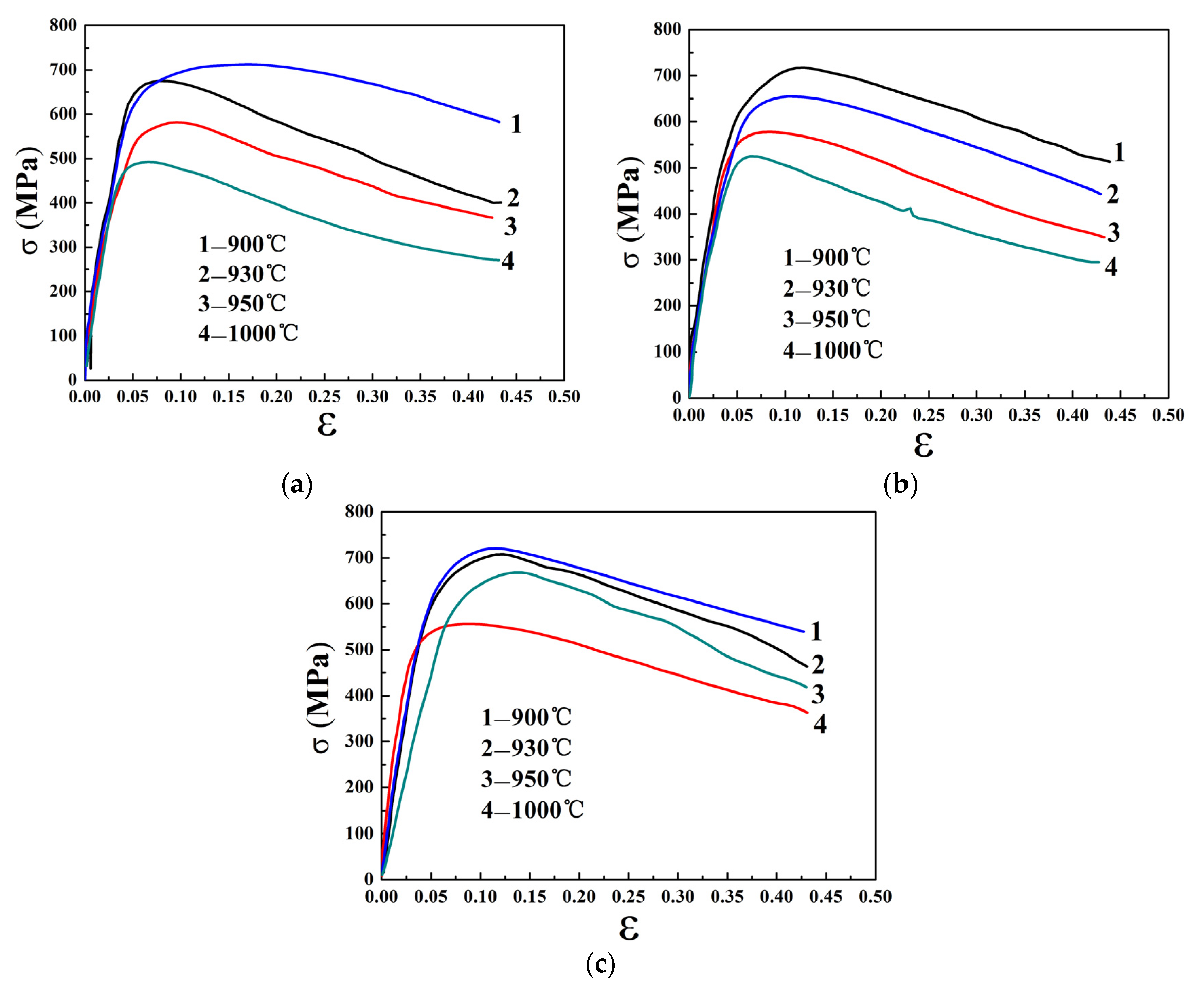
The true stress–strain curves resulting from the isothermal hot compression tests of the as-forged high Nb–TiAl alloy at different strain rates and temperature are shown in Figure 2. It can be seen that the peak stress decreases with the increase in test temperature and the decrease in strain rates, indicating as-forged high Nb–TiAl alloy also exhibits negative temperature sensitivity and positive strain rate sensitivity at a low temperature. Under all deformation conditions, the flow curves exhibit an initial strain hardening stage and a peak stress appears at a low strain(less than 0.1), followed by a moderate and continuous flow softening. The strain hardening might be caused by the increasing of dislocation density at the low strain stage and the working hardening plays a major role in this stage. With the increase in strain, dynamic recrystallization (DRX) plays a dominant role in the compression process, and the stress–strain curves exhibit a flow softening trend. It should be noted that there are no steady states in the flow curves. This occurs because DRX can only be produced at the substructure of the lamellae at a low deformation temperature and it is difficult to reach a state of equilibrium between strain hardening and flow softening.
According to the results of the isothermal hot compression tests, the dependence of the peak stress on the deformation temperature and strain rate can be expressed by Zener–Hollomon parameter (Z) [26,27]:
Ζ = ε exp ( Q R T ) = A { sinh ( α σ ) } n
where Q is the deformable activation energy, R is the gas constant, n is the stress exponent and T is the deformation temperature (K). A, α are material constants. Based on Equation (2), the deformable activation energy Q can be calculated using the following Equation (3) [26,27]:
Q = R ln [ sinh ( α σ ) ] ( 1 T ) | ε ln ε ln [ sinh ( α σ ) ] | T
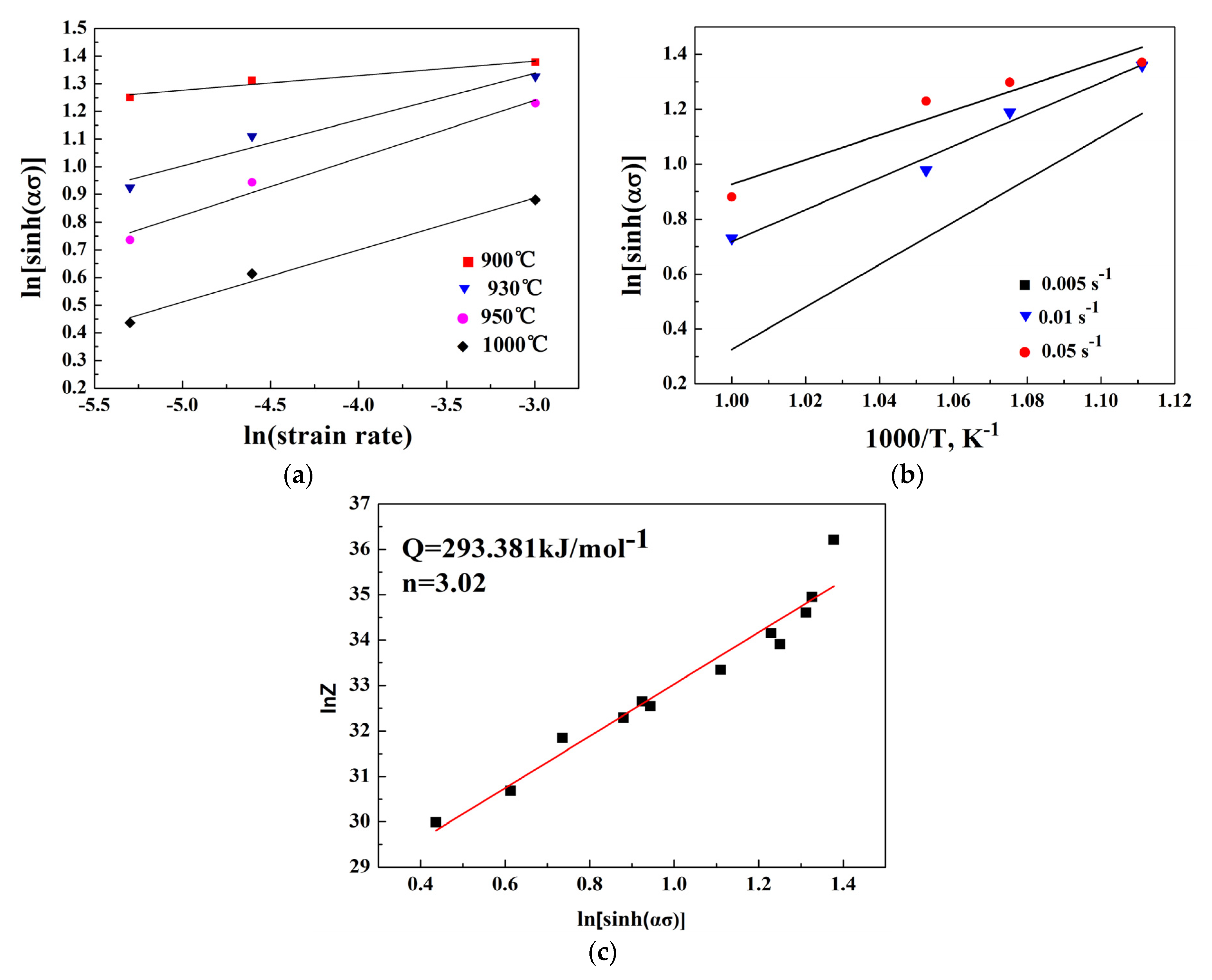
The linear relationship of flow stress with strain rate and temperature can be obtained according to the isothermal hot compression curves as shown in Figure 3a,b. The mean slope of ln[sinh(ασ)]–ln( ε ) and ln[sinh(ασ)]–1/T can be calculated, so the value of deformable activation energy Q is 293.381 kJ/mol within the temperature range of 900–1000 °C and strain rates range of 0.005–0.05 s−1, and this Q value is much lower than in some of the reports in which TiAl alloys high in Nb were cast [18]. The low Q value indicates that thermally activated processes occur easily for the as-forged high Nb–TiAl alloy, thus leading to excellent hot workability at a low forging temperature (lower than 1000 °C). Subsequently, as shown in Figure 3c, there is a linear variation in lnZ and ln[sinh(ασ)], so the stress exponent(n) is calculated as 3.02.

3.2. Distribution of Effective Strain

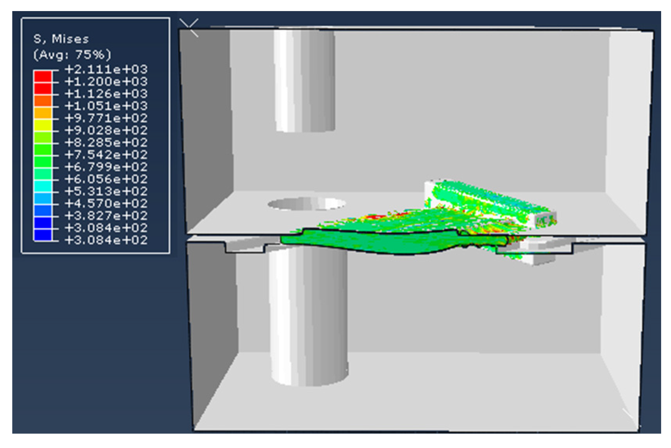
The finite element simulation of the die forging process was carried out using the results of the isothermal compression tests and the thermophysical parameters shown in Table 2. Figure 4 shows the filling state of high Nb–TiAl alloy billet in the simulated process. Figure 4 shows the final effective strain distribution of blades produced by isothermal die forging using the high Nb–TiAl alloy. It can be seen that a large effective strain appears at the edge of the blade body due to the large deformation of this area. The effective strains of the blade body center and tenon are uniformly distributed and the effective strains of flash are noticeably larger. Due to the large width-to-thickness ratio of the blade body and the limit of forging dies, the most severe effective strain appears in the blade body edge, ensuring the integrity of the blade. Figure 5a–d show the behavior with the temperature of the final effective strain distribution of the blades at a strain rate of 0.01 s−1. It can be noticed that the effective strains of the blade body center and tenon distribute more and more uniformly as the forging temperature increases. Figure 5c,e,f show the final effective strain distribution as a function of strain rate at the forging temperature of 950 °C. The simulation results indicate that the decrease in strain rate improves the final effective strain distribution of the forging blade body and tenon because the lower strain rate could promote the DRX of the as-forged TiAl alloy.

3.3. Distribution of Effective Stress

The effective stress of the forging blade is a reflection of the difficulty of deforming the material. The distribution of effective stress can show the tendency of irreversible destructive cracking during the forging process. In order to study the cracking tendency of the high Nb–TiAl alloy, the final effective stress distribution of the forging blade was analyzed during the isothermal forging process.
Figure 6 shows the final effective stress distribution of forging blades for strain rates varying from 0.05 to 0.005 s−1 and forging temperature between 900 and 1000 °C. Due to the complexity of the blade shape, the distribution of effective stress was nonuniform. Figure 6a–d show the final effective stress distribution of the forging blades at different forging temperature and at a strain rate of 0.01 s−1. When the forging temperature was 900 °C, the effective stress of the forging blade was large and nonuniformly distributed. With the increase in forging temperature, the effective stress of forging blade body and tenon decreased and the stress distribution became increasingly uniform. When the forging temperature increased to 950 °C, the maximum effective stress appeared in the flash and the portion of the blade connecting the body to the tenon. The results of the final effective strain distribution analysis showed that the deformations of the blade body center and tenon were small, which means a low effective stress and a possibility of decreasing the deformation resistance. In the simulated processes, the deformation of the blade body edge was very large, but the TiAl alloy flow in this area was limited by the severe interaction between billet and die, so the effective stress in these areas would increase. The large effective stress in the connecting part may have been the result of the uncoordinated deformation of tenon and blade body.
Figure 6c,e,f show the final effective stress distribution as a function of strain rate at the forging temperature of 950 °C. It can be seen that the final effective stress of the forging blade decreases, and its distribution becomes increasingly wide as the strain rate decreases. When the strain rate is 0.005 s−1, the final effective stress of the forging blade is very small, and the distribution is very uniform. As motioned in the description of the experimental procedure, during the isothermal die forging process, the blade temperature is uniform. According to the reference [28], the DRX could take place at a low strain rate or a high deformation temperature. Therefore, low strain rates would be advantageous for the DXR of high Nb–TiAl alloys, leading to a decrease in the deformation resistance. On the basis of the analysis above, it can be concluded that the final effective stress is very sensitive to the forging temperature and strain rate. With the increase in forging temperature and the decrease in strain rate, the final effective stress of the forging blade decreases, and its distribution becomes more uniform.

3.4. Isothermal Die Forging Experiment

In order to verify the results of the numerical analysis results, forging experiments were conducted using conventional isothermal forging equipment. The dies and blade billets were machined according to the simulation results. The die material used was a K403 nickel-based superalloy and glass lubricant was used during the forging process to reduce the wear between dies and billets. Based on the above simulated results, isothermal forging of the blades was performed on a hydraulic press with a maximum load of 6300 kN, which allocates the resistance furnace with an accuracy of 1 K and the isothermal die forging temperature was set at 950 °C. The upper die pressure speed was set at lower than 0.01 mm/s respectively. Before forging, the high Nb–TiAl alloy billets had to be sand blasted and sprayed by glass lubricant and the forging dies were heat-treated at 950 °C in the furnace for 20 min, then, the billet was assembled with the isothermal forging die. The purpose of these operations was to prevent the internal structure of the forged high Nb–TiAl alloy from over burning. At the same time, the resistance furnace on the 6300 kN isothermal forging machine was heated to 950 °C in advance. The isothermal forging die assembled with high Nb–TiAl alloy billets were placed on the 6300 kN isothermal forging machine preheated to 950 °C and maintained at that temperature for 2 h. The forging parameter information was set by computer. The isothermal die forging process was then carried out using a forging load of about 200 kN. The maximum load, when the dies were closed, was about 300 kN.
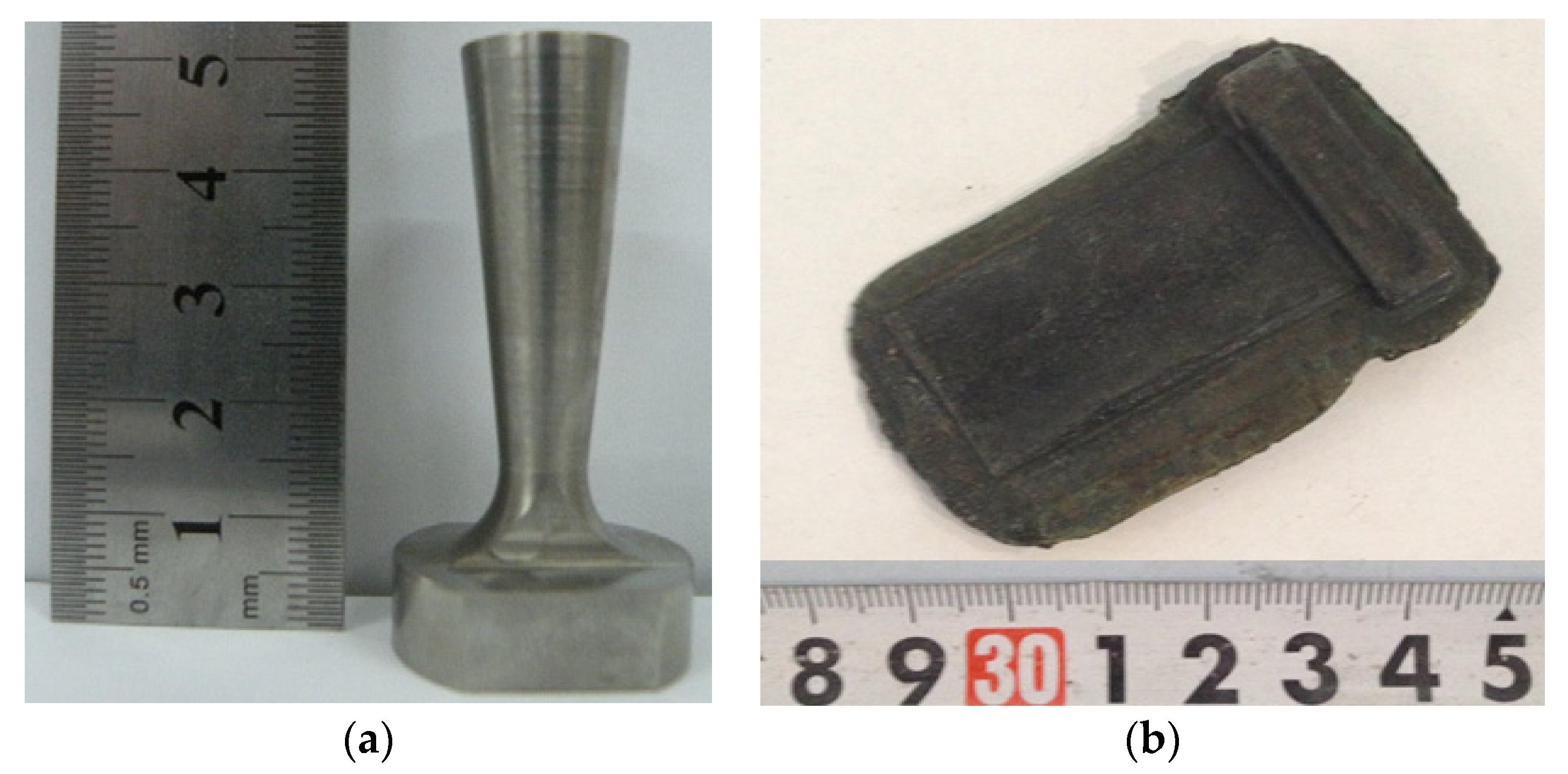
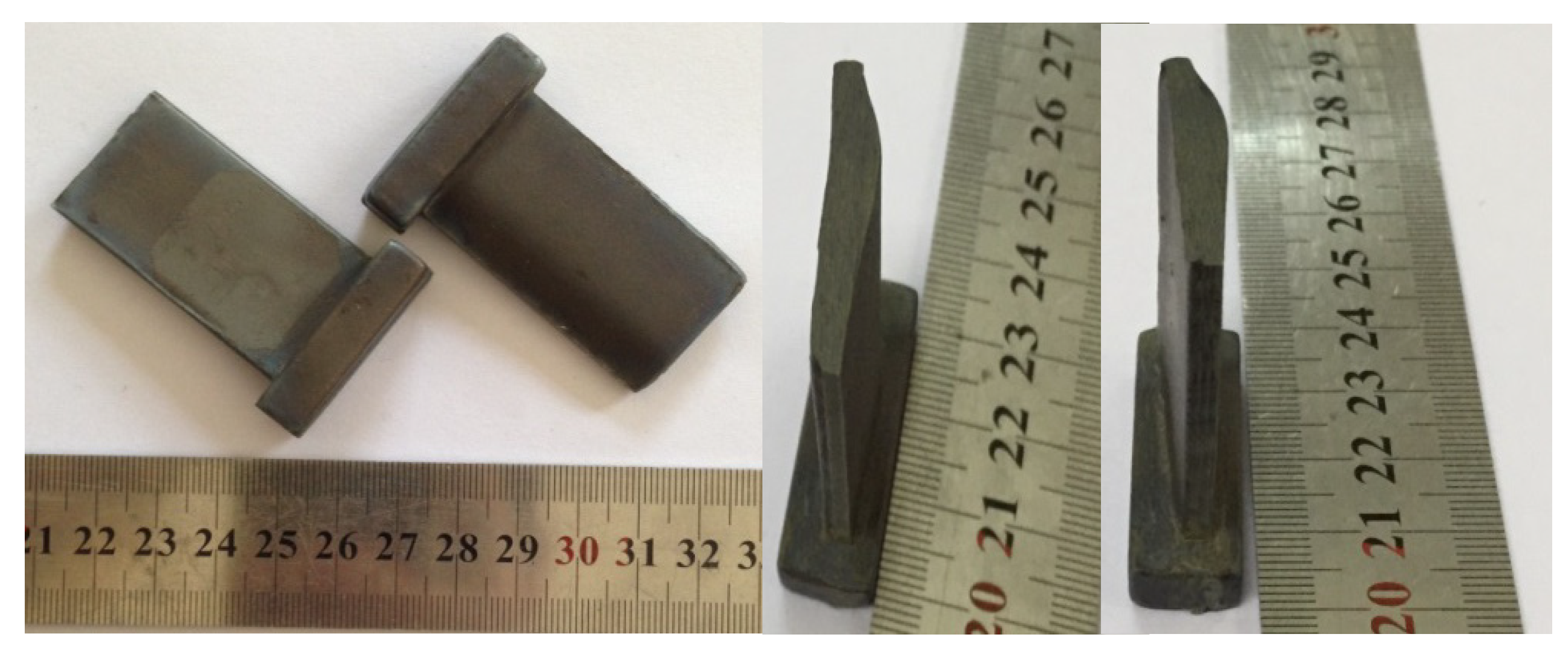
Due to the poor plasticity of high Nb–TiAl alloy at room temperature, heat treatment is not required after forging, and should be drafted immediately. The forged high Nb–TiAl blades, with well-distributed flash and high surface quality, are shown in Figure 7. The characteristics of the forged blades are in good agreement with the finite element simulation results. The sand blasted and machined blades are shown in Figure 8. The results confirm that the blades can be fabricated by isothermal die forging technology using high Nb–TiAl alloy at a low temperature (lower than 1000 °C).

3.5. Microstructure of the TiAl Alloy Blade Forged by the Isothermal Die

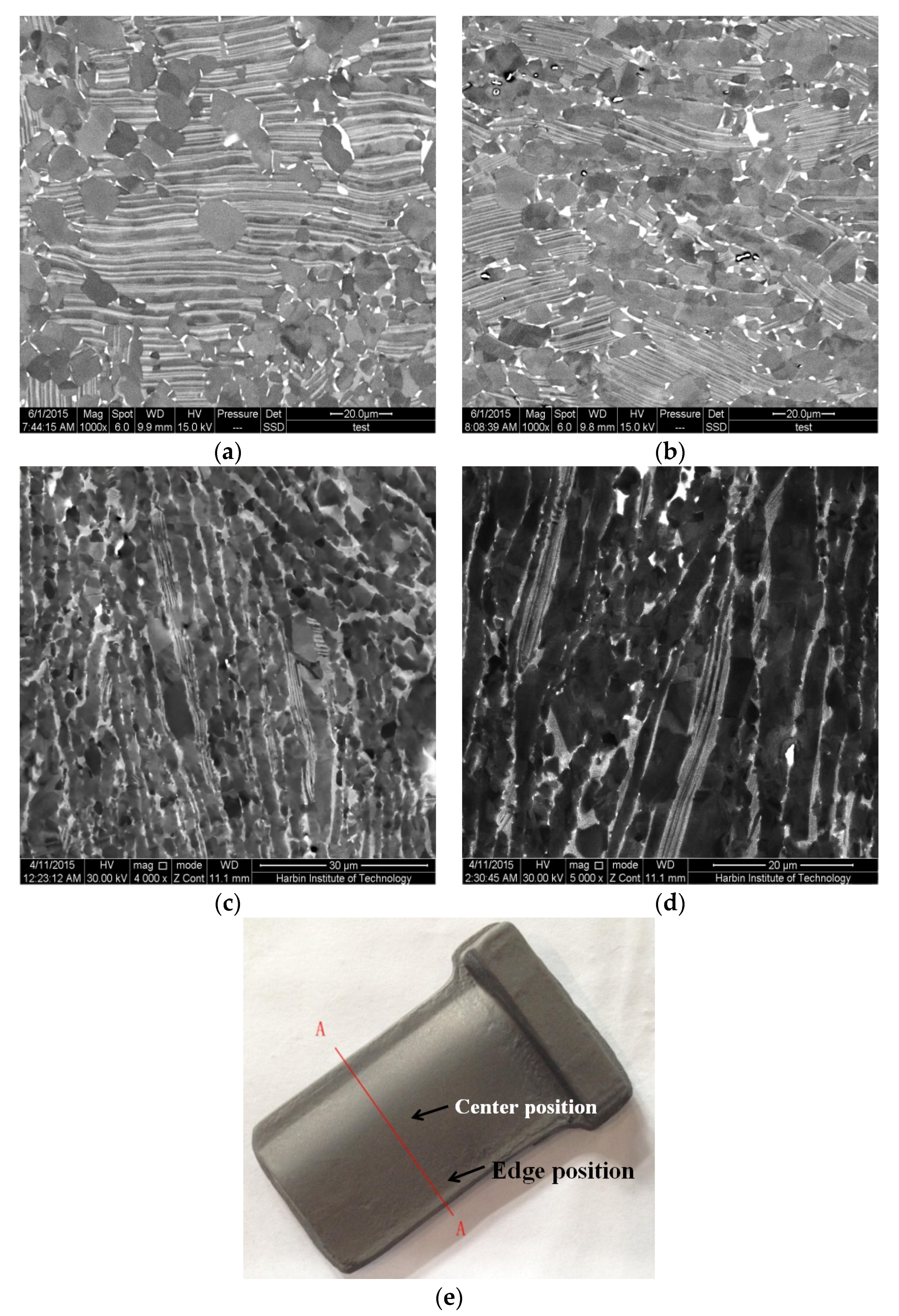
Figure 9 shows the microstructure of the high Nb–TiAl alloy before and after the isothermal die forging. As shown in Figure 9a, before the isothermal die forging process, the granular structure of the alloy consisted in coarse γ/α2 lamellar colonies and some large recrystallized equiaxed γ phase grains distributed in the lamellar colonies. After isothermal die forging, the center of the TiAl alloy blade showed a duplex microstructure, consisting of remnant lamellar colonies and recrystallized grains, as shown in Figure 9b. The remnant lamellar colonies were bended or decomposed after the isothermal die forging process and the lamellar spacing was noticeably refined. In addition, a number of recrystallized equiaxed γ grains distributed in the lamellar colonies or on lamellar boundary and a few B2 phase grains were found in the recrystallized grain boundary. Figure 9c,d show the microstructure of the TiAl alloy blade edge. It can be seen that the laths and recrystallized grains show forging flow line features. The detailed analyses of the microstructure of the blade edge are shown in higher magnification in Figure 9d, from which it can be seen that the α2 laths were refined and the γ laths had been broken down and recrystallized.
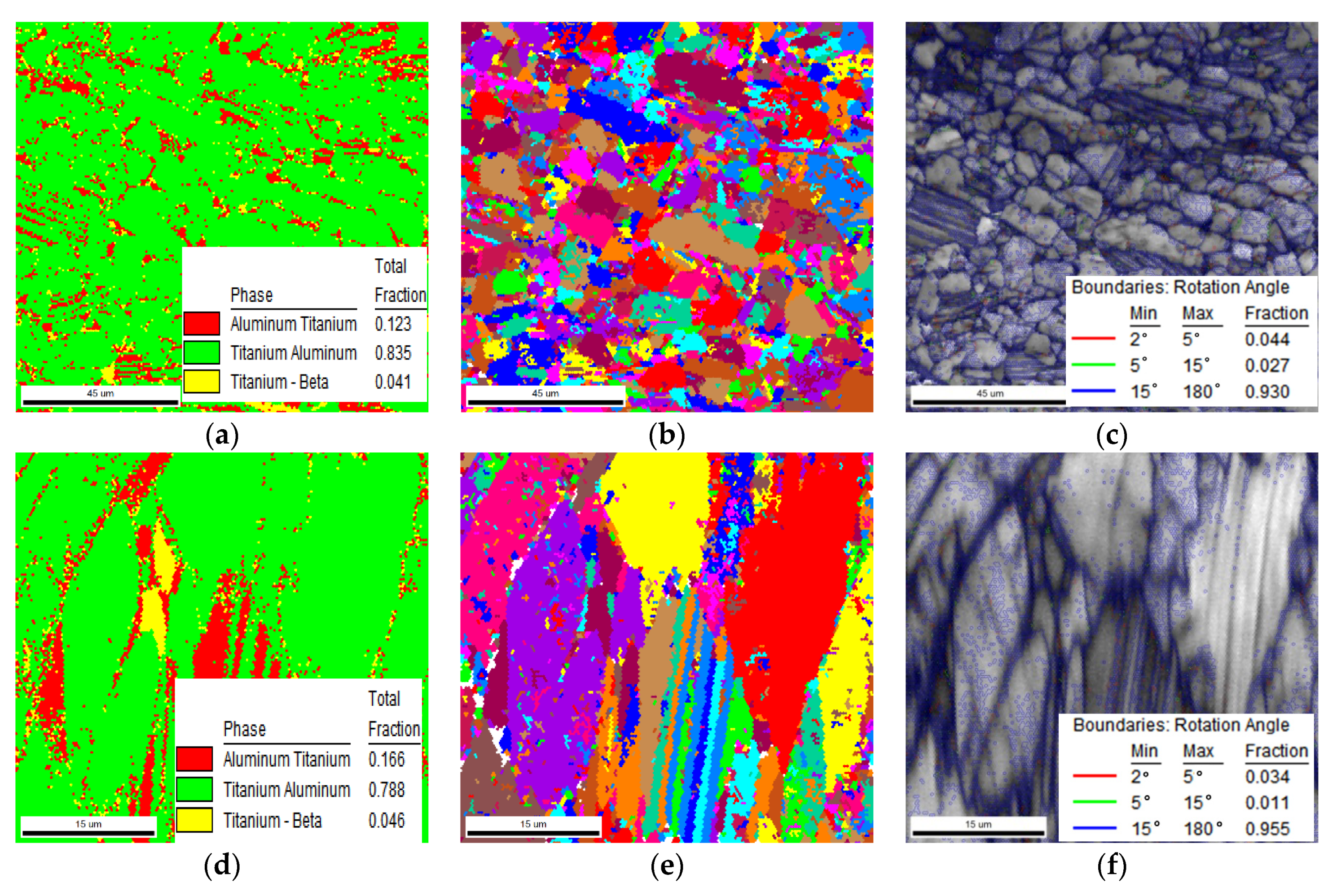
To further illustrate the microstructural evolution, the microstructures of the forged blade center and edge position were analyzed by EBSD using a 0.2 μm beam step. As shown in Figure 10a–c, the deformed microstructure of the center position mainly consisted of the γ phase (83.5%), α2 phase (12.3%) and B2 phase (4.1%). Most initial lamellae γ phase has been broken into fine equiaxial γ grains and there was a significant reduction in the lamellae α2 phase (shown in Figure 10b). Only few residual lamellae can be observed, and this phenomenon indicated that significant DRX occurred for the γ/α2 lamellae. Many studies demonstrated that DRX of γ grains is the primary mechanism for the decomposition of lamellae during hot deformation [29,30]. Furthermore, the DRX process is accompanied by the decomposition of lamellar colonies via the (α/γ)→γ transition [5], thus reducing the initial lamellae α2 phase content. The deformed microstructure in the edge position mainly consisted of the γ phase (78.8%), α2 phase (16.8%) and B2 phase (4.6%), as shown in Figure 10d–f. Banded α2 laths were still noticeable and had been refined. Moreover, combined with the SEM results, the γ laths were decomposed into very fine equiaxial γ grains, as shown in Figure 10e. The volume fractions of high angle boundaries (HAGBs) in the center position and edge position were 93% and 95.5%, respectively, further confirming that significant DRX occurred in both the center and edge positions.
In order to identify the dislocation densities and the strains in the individual grains, the grain orientation spread (GOS) was used to identify deformed γ grains in the forged blade. Figure 11 shows the grain orientation spread (GOS) map obtained from EBSD measurements performed in the center and edge positions of the forged blade. The maximum GOS value of edge position was 5.03, and there were a few low GOS value grains, marked in green and blue in Figure 10a. These results show that the deformation in the edge position was large, and most grains in the edge position were elongated, resulting in a high dislocation density. Most grains in the center position were marked as green and blue, meaning that their GOS value was low, and the maximum GOS value of the center position was 3.3. This shows that only a few grains were deformed and that most of them were DRX grains. This phenomenon indicated that significant dynamic recrystallization occurred in this position, the dislocation density was reduced, and the grain size was refined. In summary, the results of the GOS analyses matched the distributions of effective strain results from the simulations (shown in Figure 5).

4. Conclusions

In this work, the isothermal die forging of a TiAl alloy blade high in Nb content at a lower temperature was analyzed using a 3D finite element method, and a high Nb–TiAl alloy blade with high surface quality was successfully fabricated. The results of the study may be summarized as follows:
(1).
The forging temperature and speed had little effect on the final distribution of the effective strains of the blade fabricated by isothermal die forging at a temperature lower than 1000 °C. The final effective strains on the blade body and tenon were uniformly distributed.
(2).
With the increase in forging temperature and the decrease in strain rate, the final effective stress of the forging blade decreases, and its distribution became gradually uniform.
(3).
High Nb–TiAl alloy blades were successfully fabricated by isothermal die forging at a rate lower than 0.01 mm/s and a temperature of 950 °C. No macroscopic cracks formed in the blades.
(4).
The center position of the forged TiAl alloy blade showed a duplex microstructure, with the lamellar colonies and recrystallized grains showing typical forging flow line features in the edge position. The lamellae were effectively broken down into fine γ grains, and a relatively complete DRX occurred.

Author Contributions

Conceptualization, F.K.; methodology, F.K. and X.W.; software, P.X.; validation, P.X., H.Z., and X.W.; formal analysis, X.W.; investigation, P.X. and H.Z.; resources, F.K. and W.X.; data curation, P.X. and X.W.; writing—original draft preparation, X.W.; writing—review and editing, X.W. and F.K.; visualization, X.W. and F.K.; supervision, Y.C.; project administration, F.K.; funding acquisition, F.K. All authors have read and agreed to the published version of the manuscript.

Funding

This research was sponsored by State Key Laboratory for Advanced Metal and Materials foundation (Project number: 2013-ZD06), National Natural Science Foundation of China (Project number: 51471056, 51971074) and National Basic Research Program of China (Project number: 2011CB605502).

Conflicts of Interest

The authors declare no conflict of interest.

References

  1. Lin, J.P.; Zhao, L.Y.; Li, G.Y.; Zhang, L.Q.; Song, X.P.; Ye, F. Effect of Nb on oxidation behavior of high Nb containing TiAl alloys. Intermetallics 2011, 19, 131. [Google Scholar] [CrossRef]
  2. Yoshihara, M.; Kim, Y.W. Oxidation behavior of gamma alloys designed for high temperature applications. Intermetallics 2005, 13, 952. [Google Scholar] [CrossRef]
  3. Appel, F.; Oehring, M.; Wagner, R. Novel design concepts for gamma-base titanium aluminide alloys. Intermetallics 2000, 8, 1283. [Google Scholar] [CrossRef]
  4. Chen, G.; Peng, Y.; Zheng, G.; Qi, Z.; Wang, M.; Yu, H.; Dong, C.; Liu, C.T. Polysynthetic twinned TiAl single crystals for high-temperature applications. Nat. Mater. 2016, 15, 876–881. [Google Scholar] [CrossRef]
  5. Zhang, S.Z.; Zhang, C.J.; Du, Z.X.; Hou, Z.P.; Lin, P.; Chen, Y.Y. Microstructure and tensile properties of hot fogred high Nb containing TiAl based alloy with initial near lamellar microstructure. Mater. Sci. Eng. A 2015, 642, 16–21. [Google Scholar] [CrossRef]
  6. Janschek, P. Wrought TiAl blades. Mater. Today 2015, 2, 92–97. [Google Scholar] [CrossRef]
  7. Yang, L.; Chai, L.H.; Liang, Y.F.; Zhang, Y.W.; Bao, C.L.; Liu, S.B.; Lin, J.P. Numerical simulation and experimental verification of gravity and centrifugal investment casting low pressure turbine blades for high Nb-TiAl alloy. Intermetallics 2015, 66, 149–155. [Google Scholar] [CrossRef]
  8. Paul, J.D.H.; Appel, F.; Wagner, R. The compression behaviour of niobium alloyed γ-titanium alumindies. Acta Mater. 1998, 46, 1075. [Google Scholar] [CrossRef]
  9. Song, X.P.; Chen, G.L. Determination of the stacking fault energy in high-Nb γ-TiAl. J. Mater. Sci. Lett. 2001, 20, 659. [Google Scholar] [CrossRef]
  10. Wang, Y.H.; Lin, J.P.; Xu, X.J.; He, Y.H.; Wang, Y.L.; Chen, G.L. Effect of fabrication process on microstructure of high Nb containing TiAl alloy. J. Alloy. Compd. 2008, 458, 313. [Google Scholar] [CrossRef]
  11. Li, J.B.; Liu, Y.; Liu, B.; Wang, Y.; Cao, P.; Zhou, C.X.; Xiang, C.J.; He, Y.H. High temperature deformation behavior of near γ-phase high Nb-containing TiAl alloy. Intermetallics 2014, 52, 49. [Google Scholar] [CrossRef]
  12. Stark, A.; Rackel, M.; Tankoua, A.T.; Oehring, M.; Schell, N.; Lottermoser, L.; Schreyer, A.; Pyczak, F. In situ high-energy X-ray diffraction during hot-forming of a multiphase TiAl alloy. Metals 2015, 5, 2252–2265. [Google Scholar] [CrossRef] [Green Version]
  13. Brooks, J.W.; Dean, T.A.; Hu, Z.M.; Wey, E. Three-dimensional finite element modelling of a titanium aluminide aerofoil forging. J. Mater. Process. Tech. 1998, 80–81, 149. [Google Scholar] [CrossRef]
  14. Tetsui, T.; Shindo, K.; Kobayashi, S.; Takeyama, M. A newly developed hot worked TiAl alloy for blades and structural components. Scripta Mater. 2002, 47, 399. [Google Scholar] [CrossRef]
  15. Appel, F.; Oehring, M.; Paul, J.D.H.; Klinkenberg, C.; Carneiro, T. Physical aspects of hot-working gamma-based titanium aluminides. Intermetallics 2004, 12, 791. [Google Scholar] [CrossRef]
  16. Xu, W.C.; Shan, D.B.; Zhang, H.; Li, X.A.; Zhang, Y.Z.; Nutt, S. Effects of extrusion deformation on microstructure, mechanical properties and hot workability of β containing TiAl alloy. Mat. Sci. Eng. A 2013, 571, 199. [Google Scholar] [CrossRef]
  17. Xu, Z.F.; Xu, X.J.; Lin, J.P.; Zhang, Y.; Wang, Y.L.; Lin, Z.; Chen, G.L. Homogenization treatment of high Nb containing TiAl alloys with as-cast and as-forged microstructures. Rare Met. 2008, 27, 181. [Google Scholar] [CrossRef]
  18. Liang, C.; Hui, C.; Bin, T.; Hongchao, K.; Jinshan, L. Simulation of microstructure for hot pack-forging of a high Nb containing TiAl alloy. Rare Metal. Mater. Eng. 2014, 43, 36–41. [Google Scholar] [CrossRef]
  19. Clemens, H.; Mayer, S. Design, Processing, Microstructure, Properties, and Applications of Advanced Intermetallic TiAl Alloys. Adv. Eng. Mater. 2013, 15, 191–215. [Google Scholar] [CrossRef]
  20. Cheng, L.; Chang, H.; Tang, B.; Kou, H.; Li, J. Deformation and dynamic recrystallization behavior of a high Nb containing TiAl alloy. J. Alloy. Compd. 2013, 552, 363–369. [Google Scholar] [CrossRef]
  21. Zhang, S.Z.; Zhang, C.J.; Du, Z.X.; Hou, Z.P.; Lin, P.; Kong, F.T.; Chen, Y.Y. Deformation behavior of high Nb containing TiAl based alloy in α + γ two phase field region. Mater. Des. 2016, 90, 225–229. [Google Scholar] [CrossRef]
  22. Zheng, J.Z.; Zhang, L.Q.; Hou, Y.M.; Ma, X.L.; Lin, J.P. Quasi isothermal forging simulation of β-γ TiAl alloy containing high content of Nb, Acta Metallurgica Sinica. Acta Metall. Sin. 2013, 49, 1439. [Google Scholar] [CrossRef]
  23. Goetz, R.; Semiatin, S. The adiabatic correction factor for deformation heating during the uniaxial compression test. J. Mater. Eng. Perfor. 2001, 10, 710–717. [Google Scholar] [CrossRef]
  24. Shan, D.; Yi, X.; Yan, L. Three-dimensional rigid-plastic finite-element analysis of the isothermal precision forging of a cylindrical housing. J. Mater. Process. Technol. 2000, 102, 188–192. [Google Scholar] [CrossRef]
  25. Xu, P. Fundamental Research on Isothermal Die Forging of High Nb-TiAl Alloy. Master’s Thesis, Harbin Institute of Technology, Harbin, China, 29 June 2015. [Google Scholar]
  26. Sellars, C.; McTegart, W. On the mechanism of hot deformation. Acta Metall. 1966, 14, 1136–1138. [Google Scholar] [CrossRef]
  27. Gupta, R.; Murty, S.N.; Pant, B.; Agarwala, V.; Sinha, P. Hot workability of γ + α2 titanium aluminide: Development of processing map and constitutive equations. Mater. Sci. Eng. A 2012, 551, 169–186. [Google Scholar] [CrossRef]
  28. Xu, Z.; Yao, Z.K. High temperature deformation and crystallization of metal materials. Ordnance Mater. Sci. Eng. 1986, 2, 35. (In Chinese) [Google Scholar]
  29. Appel, F.; Paul, J.D.H.; Oehring, M. Gamma Titanium Aluminide Alloys: Science and Technology; JohnWiley & Sons: Weinheim, Germany, 2011. [Google Scholar]
  30. Zhang, W.J.; Lorenz, U.; Appel, F. Recovery, recrystallization and phase transformations during thermomechanical processing and treatment of TiAl-based alloys. Acta Mater. 2000, 48, 2803–2813. [Google Scholar] [CrossRef]
Figure 1. Model of blade isothermal die forging: (a) simulation assembly illustration and (b) primary mesh of billet.
Metals 10 00757 g001
Figure 2. True stress–strain curves of TiAl alloy at different strain rates: (a) 0.005 s−1; (b) 0.01 s−1; (c) 0.05 s−1.
Metals 10 00757 g002
Figure 3. (a) Variation of flow stress with strain rate at different temperatures. (b) Arrhenius plot showing the variation of flow stress with temperature at different strain rates and (c) linear variation of lnZ with ln[sinh(ασ)].
Metals 10 00757 g003
Figure 4. Filling of high Nb–TiAl alloy billet in the simulated process.
Metals 10 00757 g004
Figure 5. Effective strain distributions at different forging temperatures and strain rates: (a) 900 °C, 0.01 s−1; (b) 930 °C, 0.01 s−1; (c) 950 °C, 0.01 s−1; (d) 1000 °C, 0.01 s−1; (e) 950 °C, 0.05 s−1; (f) 950 °C, 0.005 s−1.
Metals 10 00757 g005
Figure 6. Effective stress distributions at different forging temperatures and strain rates: (a) 900 °C, 0.01 s−1; (b) 930 °C, 0.01 s−1; (c) 950 °C, 0.01 s−1; (d) 1000 °C, 0.01 s−1; (e) 950 °C, 0.05 s−1; (f) 950 °C, 0.005 s−1.
Metals 10 00757 g006
Figure 7. Images of (a) initial billet and (b) high Nb–TiAl blade forged by the isothermal-die.
Metals 10 00757 g007
Figure 8. Images of the sandblasted high Nb–TiAl alloy blades.
Metals 10 00757 g008
Figure 9. Microstructure of TiAl alloy before and after the isothermal die forging: (a) before the isothermal die forging; (b) center position of the forged blade; (c) edge position of the forged blade; (d) high magnification of (c); (e) sample position of (b) and (c) in the forged blades.
Metals 10 00757 g009
Figure 10. Electron back scatter diffraction (EBSD) maps of the forged blade: (a) phase distribution of center position; (b) grain distribution of center position; (c) grain misorientation angle of center position; (d) phase distribution of edge position; (e) grain distribution of edge position; (f) grain misorientation angle of edge position.
Metals 10 00757 g010
Figure 11. The grain orientation spread (GOS) maps of different positions of the forged blade: (a) center position; (b) edge position.
Metals 10 00757 g011
Table 1. Isothermal hot compression test parameters.
Strain Rate0.005 s−10.01 s−10.05 s−1
Temperature
900 °C40%40%40%
930 °C50%40%40%
950 °C40%40%40%
1000 °C40%40%40%
Table 2. Thermophysical parameters of high Nb–TiAl alloy, data from [25].
Temperature (°C)Thermal Diffusivity (10−6 m2·s−1)Heat Capacity (J·K−1·g−1)Thermal Conductivity (W·K−1·m−1)Coefficient of Thermal Expansion (mm·mm−1·C)
254.1058811.12.05 × 105
5006.9063820.02.11 × 105
7007.3365821.72.14 × 105
8007.8866823.12.19 × 105
9007.6067823.12.22 × 105
10007.1268821.52.24 × 105
11006.7969819.82.30 × 105