Article

Effect of Annealing Heat Treatment on the Microstructural Evolution and Mechanical Properties of Hot Isostatic Pressed 316L Stainless Steel Fabricated by Laser Powder Bed Fusion

1
Planetary and Space Science Centre, University of New Brunswick, Fredericton, NB E3B 5A3, Canada
2
Voestalpine Additive Manufacturing Centre Ltd., Mississauga, ON L5N 7Y3, Canada
3
Department of Mechanical Engineering, University of New Brunswick, Fredericton, NB E3B 5A3, Canada
*
Author to whom correspondence should be addressed.
These authors equally contributed to this work.
Metals 2020, 10(6), 753; https://doi.org/10.3390/met10060753
Submission received: 30 April 2020 / Revised: 29 May 2020 / Accepted: 2 June 2020 / Published: 5 June 2020

Abstract

:
In this work, the microstructural features and mechanical properties of an additively manufactured 316L stainless steel have been determined. Three types of samples were characterized: (i) as printed (AP), (ii) annealing heat treated (AHT), and (iii) hot isostatic pressed and annealing heat treated (HIP + AHT). Microstructural analysis reveals that the AP sample formed melt pool boundaries with nano-scale cellular structures. These structures disappeared after annealing heat treatment and hot isostatic pressing. The AP and AHT samples have similar grain morphologies; however, the latter has a lower dislocation density and contains precipitates. Conversely, the HIP + AHT sample displays polygon-shaped grains with twin structures; a completely different morphology compared to the first two samples. Optical micrography reveals that the application of hot isostatic pressing reduces the porosity generated after laser processing. The tensile strengths of all the samples are comparable (about 600 MPa); however, the elongation of the HIP + AHT sample (48%) was superior to that of other two samples. The enhanced ductility of the HIP + AHT sample, however, resulted in lower yield strength. Based on these findings, annealing heat treatment after hot isostatic pressing was found to improve the ductility of as-printed 316L stainless steel by as much as 130%, without sacrificing tensile strength, but the sample may have a reduced (40%) yield strength. The tensile strength determined here has been shown to be higher than that of the hot isostatic pressed, additively manufactured 316L stainless steel available from the literature.

1. Introduction

Additive manufacturing (AM) technology is a layer-by-layer deposition technique to form a solid material using a computerized three-dimensional model [1]. The integration of this technology with various commercial applications represents one of the innovations of Industry 4.0 [2]. Various manufacturing sectors are aggressively exploring AM due to its benefits, such as reduced manufacturing steps, higher material utilization, and the capability of complex design [3]. Although there are numerous types of AM [4], laser powder bed fusion (LPBF) is one of the most common techniques being explored due to its ability to generate complex shapes and geometries [5,6]. The method employs a laser gun to selectively melt metallic powders in a layer-by-layer fashion until a final product is achieved. The LPBF process is being extensively studied to produce parts and components using nickel-based alloy, titanium alloys, aluminum alloys, steels, high-entropy alloys, shape memory alloys and copper alloys [7,8,9,10,11,12,13,14,15,16,17,18,19,20,21]. AM products currently produced by LPBF have a wide range of applications in the aerospace, defense, automotive, medical, and oil and gas sectors.
Austenitic stainless steel is one of the most commonly used alloys in the marine, biomedical and aerospace industries because of its superior ductility and superb corrosion resistance [22,23,24]. Products using this material are widely fabricated using traditional manufacturing techniques, such as casting, forging, extrusion and machining. However, such methods limit the manufacturing of objects with intricate features and they generate significant material waste. Consequently, the manufacturing sector is actively exploring the use of AM technology to overcome these limitations.
To date, a significant amount of research has been done to produce 316L austenitic stainless steel via the LPBF process [15,25,26]. For example, the process parameters, such as laser power, scan speed, layer thickness, and hatch spacing, have been optimized to minimize the presence of porosity, which is detrimental to the mechanical properties of the material [5,27,28]. These process parameters can also be tailored to control the crystallographic texture during solidification [29]. Additively manufactured 316L stainless steel usually requires post-processing heat treatment cycles (i.e., recovery, homogenization, and annealing) to maximize the strength and ductility. The application of heat treatment removes the melt pool boundaries and microsegregation in the as-printed alloy. This process results in the improved mechanical properties of the material by modifying the microstructure. However, despite the improvement of the properties, the heat treatment process is not presently designed to remove any porosity inherent in the AM process.
To date, although there are numerous studies related to post-processing techniques of as-printed 316L stainless steel [30,31,32,33,34,35,36,37], there is very limited data available regarding the annealing heat treatment of a hot isostatic pressed sample. This technique is known to increase the relative density of the material. The goal of this work is to understand the effect of annealing heat treatment (AHT) after the hot isostatic pressing (HIP) of additively manufactured 316L stainless steel. Although annealing heat treatment requires an additional manufacturing step, any improvement in the mechanical properties would potentially expand the application of AM 316L stainless steel to industries that require higher strength/ductility (combined with superior corrosion resistance). Note that the mechanical properties of additively manufactured alloys remain an issue with respect to the certification of AM components. This research is the initial step to explore the possibility of further increasing the mechanical properties of AM alloy following HIP.
In this work, as-printed 316L stainless steel samples were subjected to two types of post-processing: (i) annealing heat treatment, and (ii) a combination of HIP and AHT. The effects of such post-processing techniques on the porosity, microstructures, mechanical properties and fracture mechanisms were evaluated. The mechanical properties were then compared to the data from hot isostatic pressed, additively manufactured 316L stainless steel available from the literature.

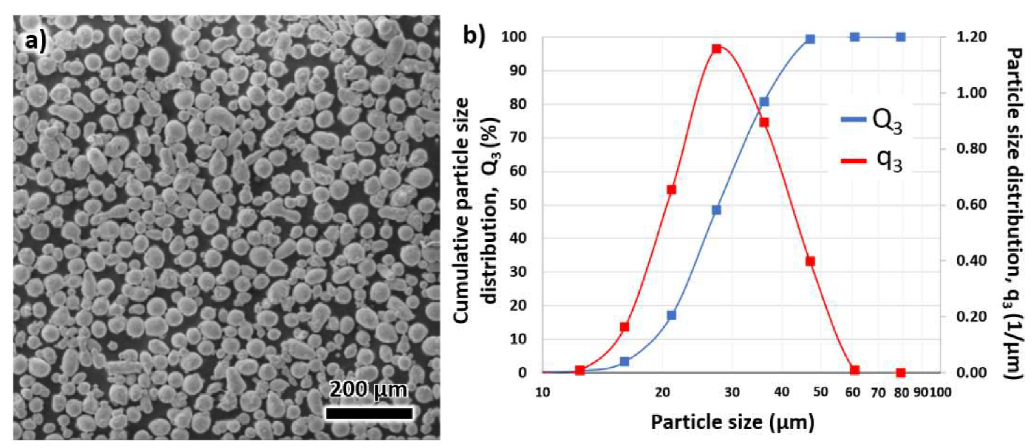
2. Materials and Methods

Samples of 316L stainless steel used in this study were manufactured and supplied by the voestalpine Additive Manufacturing Center Ltd., Mississauga, ON, Canada (vAMC). Gas atomized powders of the alloy, with diameters in the range of 15–25 μm, were processed by LPBF utilizing an EOS M290 machine (EOS, Krailling, Germany). The chemical composition of the powder and the build is provided in Table 1. This composition was confirmed using an inductively coupled plasma process following ASTM D1976-18Mod and ASTM E1019-18. No significant changes in the composition were observed after manufacturing.
A scanning electron microscope (SEM) image of the powders is displayed in Figure 1a using a Tescan Vega3 electron microscope (Tescan, Kohoutovice, Czech Republic). The particle size distribution is also presented in Figure 1b. This information was obtained using digital image processing from CAMSIZER X2 Retsch Technology (Retsch Technology GmbH, Haan, Germany). The Hall flow rate of the powders was 14.89 s per 50 g. Printing was performed using a deposited volumetric energy density from 30 to 40 J/mm3 employing a striped meander scanning with a rotation angle of 55° and a stripe width of 12 mm. The laser power was 350 W, laser speed 1000 mm/s, and the layer thickness 60 μm. A hatch distance of 200 μm was employed. The chamber was filled with argon gas to minimize oxidation.
Two types of samples were fabricated: (i) 10 mm cubes for the initial microstructural analysis, and (ii) cylindrical samples with lengths and diameters of 86 mm and 14 mm, respectively, for tensile testing. For the cylindrical samples, two types were manufactured: (i) with lengths parallel to the building direction (BD), and (ii) with lengths parallel to the transverse direction (TD). These samples allowed for the measurement of the physical properties in both directions.
The as-printed (AP) samples underwent two types of heat treatment: (i) annealing (AHT) at 900 °C for 2 h followed by nitrogen quenching at 5–6 bar until 65 °C, and (ii) hot isostatic pressing (HIP) at 1163 °C for 3 h at a pressure of ~1 Mbar followed by the same AHT process in (i) above. Both heat treatment cycles utilized an argon gas atmosphere. The AP, AHT and HIP + AHT samples were polished using silicon carbide papers with grit from 400 to 1200. The rough polishing was followed by fine polishing using 3 and 1 μm diamond suspensions.
The samples for SEM imaging were electro etched by 10% oxalic acid with an applied voltage of 5 V for 10 s at room temperature to prepare the microstructures for analysis. Another separate set of samples was subjected to final polishing using a Buehler Vibromet 2 polisher (Buehler, Lake Bluff, IL, USA) with 0.02 μm silica suspension for 24 h (for electron backscatter diffraction (EBSD) analysis). Electron microscopy was carried out using a Thermo scientific Scios 2 electron microscope (Thermo Fisher Scientific Inc, Waltham, MA, USA) and a Hitachi SU70 (Hitachi, Tokyo, Japan) equipped with a HKL Channel 5 software (5.11.20405.0, HKL Channel 5, Abingdon, United Kingdom). The SEM images were obtained using secondary electron imaging mode employing 20 kV. For all the EBSD images, a step size of 0.5 μm was used.
Optical micrographs were acquired using a Zeta Instruments optical microscope (KLA Corporation, Milpitas, CA, USA). ImageJ analysis software (1.52A, ImageJ, Madison, WI, USA) was utilized for the measurement of relative density using five images to verify the validity of the measurements. The error bars were calculated based on the standard deviation from five measurements.
Tensile testing was performed in accordance with ASTM E8. The yield strength was determined using the 0.2% offset method. A total of five tests for each condition were performed to validate the accuracy of the results. The fractured surface was analyzed using SEM imaging and EBSD analysis.

3. Results and Discussion

It is well known that porosity can significantly alter the mechanical properties of additively manufactured alloys [38]. Thus, optical micrographs of AP, AHT, and HIP + AHT samples were obtained to measure the relative density of the samples. The AP and AHT samples displayed higher porosity compared to the HIP + AHT sample. These observations are reflected in Figure 2. The relative densities of the AP and AHT samples were 99.6% and 99.5%, respectively. Although the AHT sample provided better overall mechanical properties than that of the AP sample, it appears that the relative density was not affected, which was consistent with previous work [39]. On the other hand, the HIP + AHT sample attained a relative density of 99.9%. It appears that the applied pressure during HIP allows the material to flow and sinter at elevated temperatures. Thus, the pores created by laser processing can be annihilated, which translates to a higher relative density of the material.

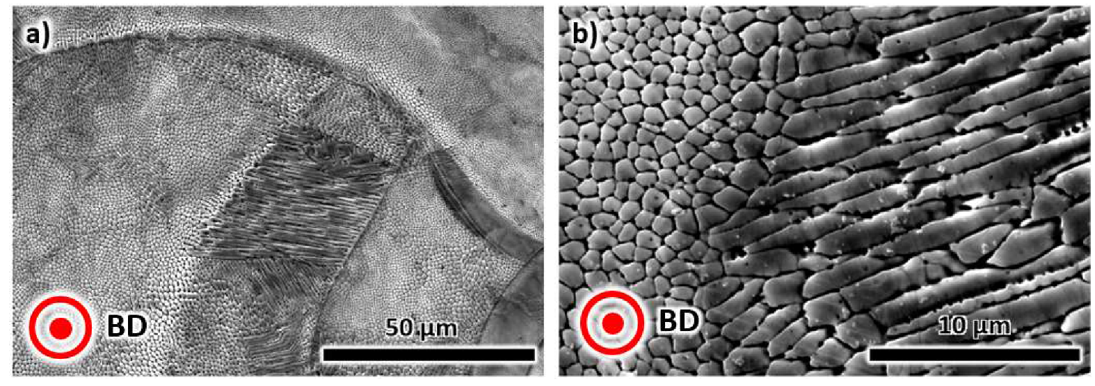
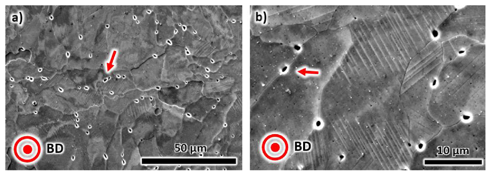
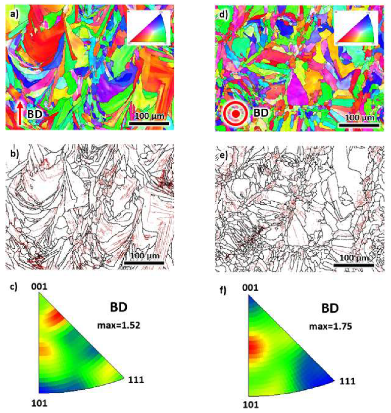
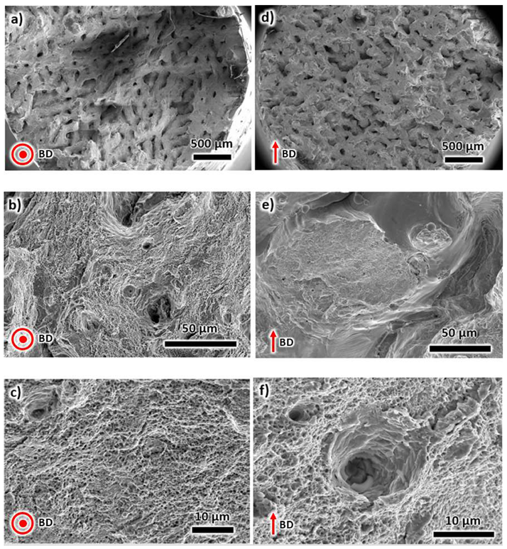
3.1. Microstructural Characterization of as-Printed (AP) AM 316L Stainless Steel

Low- and high-magnification microstructures show cellular (Figure 3a) and dendritic (Figure 3b) structures due to the rapid solidification with a cooling rate of about 104–106 °C/s [40]. This cooling rate restricts the formation of precipitates during solidification. No evidence of the precipitates was found in the SEM images of the AP sample. The microstructural properties in the SEM images are consistent with the findings in the literature [41].
EBSD analysis was performed on the plane containing the building direction (BD) to understand the microstructural evolution during solidification (see Figure 4a–c). The EBSD map in Figure 4a displays columnar and elongate grains, with the growth direction aligned with the building direction. It appears that the growth of the grains was affected by the melt pool boundaries, as depicted by the shape of the grains. Visually, the grains do not have a preferred orientation despite having a growth direction during solidification. The same EBSD results were used to analyze the dislocation density present in the material after printing. Thus, grain boundary maps showing low angle (LAGBs) and high angle (HAGBs) grain boundaries were generated, as displayed in Figure 4b. The LAGBs represent those grains with misorientations between 2° and 15°. These boundaries are associated with the dislocation density of the material [42]. On the other hand, the HAGBs define the boundary between each grain and are characterized by grain misorientations of greater than 15°. The LAGB fraction of the as-printed sample along the BD was 44.8%. The crystallographic texture was also determined using an inverse pole figure (IPF) representation (Figure 4c). The reference direction for the map is the BD. For consistency, the same reference direction was utilized in all the IPF maps in this work. Although the (304) plane appears to be the preferred orientation after printing, note that the texture intensity factor was only 1.55. This value is reasonably low; thus, the overall texture of the material is considered as random.
A similar EBSD analysis was carried out on the plane normal to the BD, referred to here as the TD (transverse direction), as displayed in Figure 4d–f. The morphology of grains along the TD is more equiaxed, as shown in Figure 4d. The grains are also smaller. This morphology corresponds to the cross-sectional area of the columnar grains in Figure 4a. Interestingly, there are localized areas with fine grain microstructures (with grain sizes of around 5 μm), which may be due to static and/or dynamic recrystallization. The driving force for this phenomenon could be the residual stresses generated after printing as a result of rapid solidification [43,44]. The grain boundary map of the same EBSD data is displayed in Figure 4e. The fraction of LAGBs is 47.7%. This number is consistent with the one measured from the BD. The IPF representation of grains in the TD direction is shown in Figure 4f. Similar to the results from the BD (Figure 4c), the overall texture is considered as random due to the low-texture intensity factor (1.42), although the (001) and (214) planes appear to have the highest intensity.

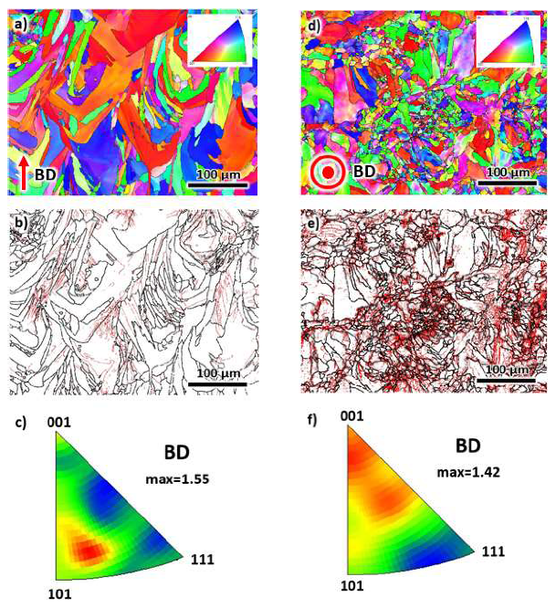
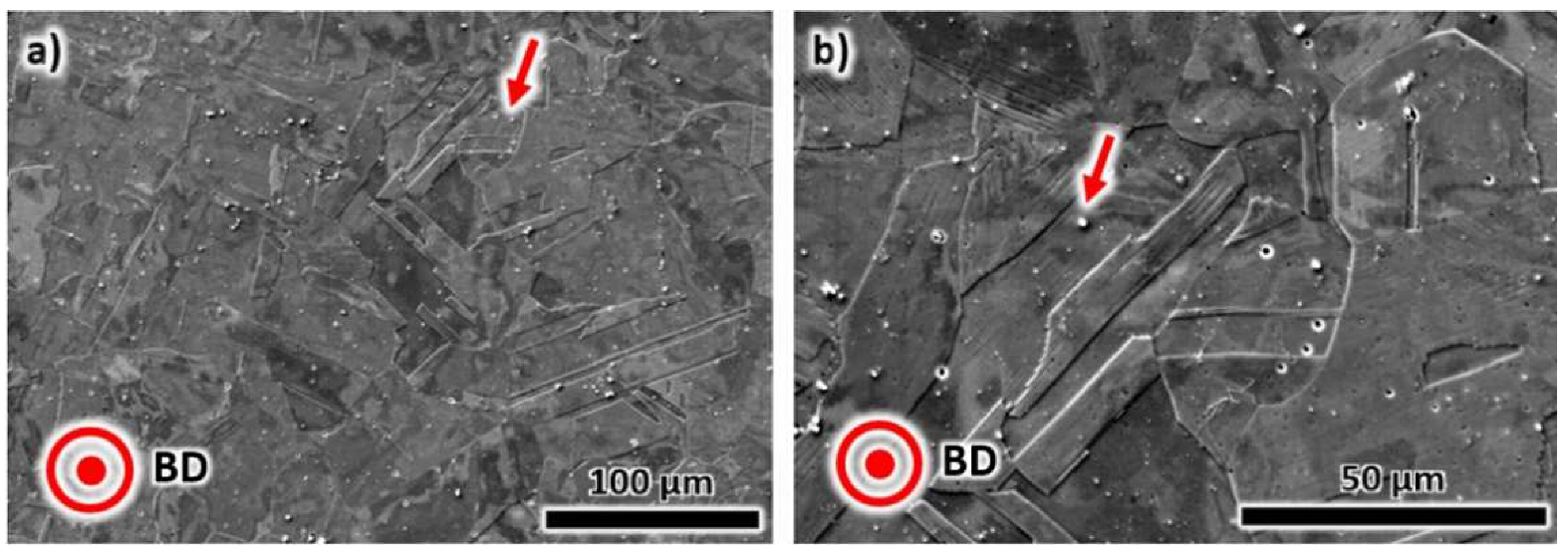
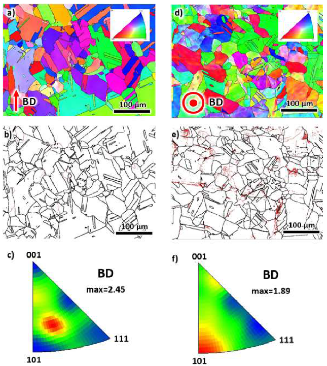
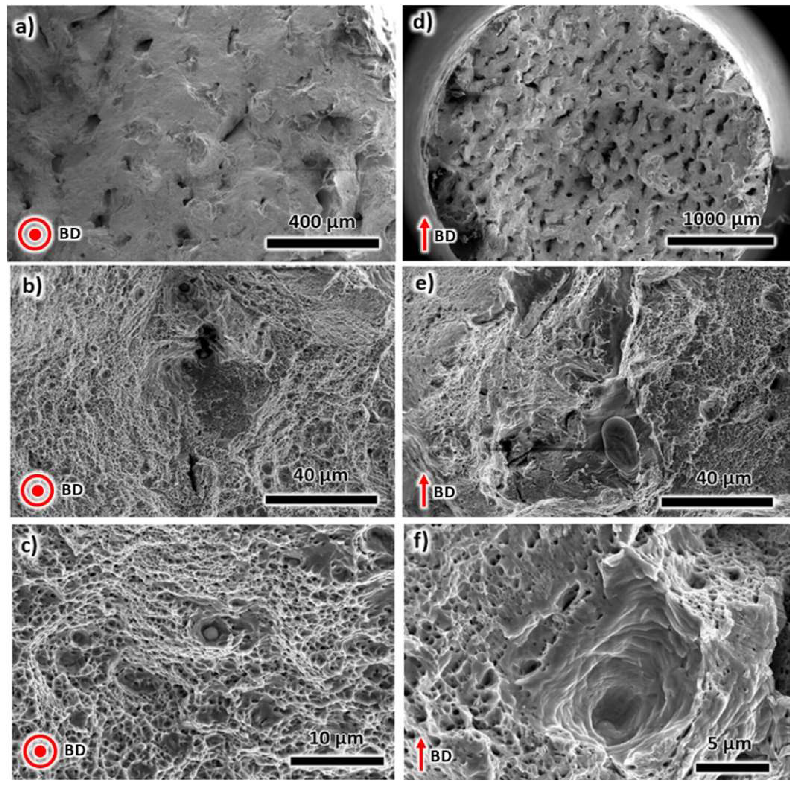
3.2. Microstructural Evolution after Annealing Heat Treatment (AHT)

The as-printed sample was subjected to annealing heat treatment at 900 °C for 2 h (see Figure 5a,b). The annealing process did not significantly change the shape of the grains, although the melt pool boundaries, scan tracks and nano-scale cellular and dendritic structures disappeared. Moreover, nano-scale precipitates, which nucleated along the grain boundaries are now evident. For reference, the precipitates were marked with red arrows. These precipitates played an important role in strengthening the alloy [45,46]. There were also nano-scale twin-like structures; however, these were not detected in the EBSD analysis below.
The EBSD analysis after annealing heat treatment was displayed in Figure 6. The EBSD map of the BD (see Figure 6a) has a similar morphology with the as-printed sample in Figure 4a. The grains have columnar and elongated features, with the growth direction aligned with the building direction. The grain growth also appears to be affected by the presence of melt pools. The fraction of LAGBs in Figure 4b was determined, and the results show a lower value than that of the as-printed samples, which is 41%. The overall crystallographic texture (see Figure 4c) depicts a random orientation, as supported by the low-texture intensity factor of 1.52, although some planes are more apparent, such as (001) and (102).
The EBSD-acquired microstructure was also obtained from the TD, as displayed in Figure 6d–f. Although the morphology of the grains in Figure 6d is similar to that of the as-printed samples in Figure 4d, there is a reduced region of fine grain structure. The grain size is ~10 μm, and is larger than the AP condition due to the grain growth during AHT. Similar to the microstructure of the as-printed sample, an equiaxed feature associated with the cross-sectional area of the elongated grains is observed (Figure 6a). The fraction of LAGBs in the TD is 36.8% (see Figure 6e). This value is lower than the measured values in the as-printed condition since the heat treatment process is known to reduce the dislocation density in the alloy. Thus, in this work, the AHT sample has a lower dislocation density than that of the AP sample. In addition, although the (102) accounts for the highest orientation, the general crystallographic texture is random with a texture intensity factor of 1.75, see Figure 6f.

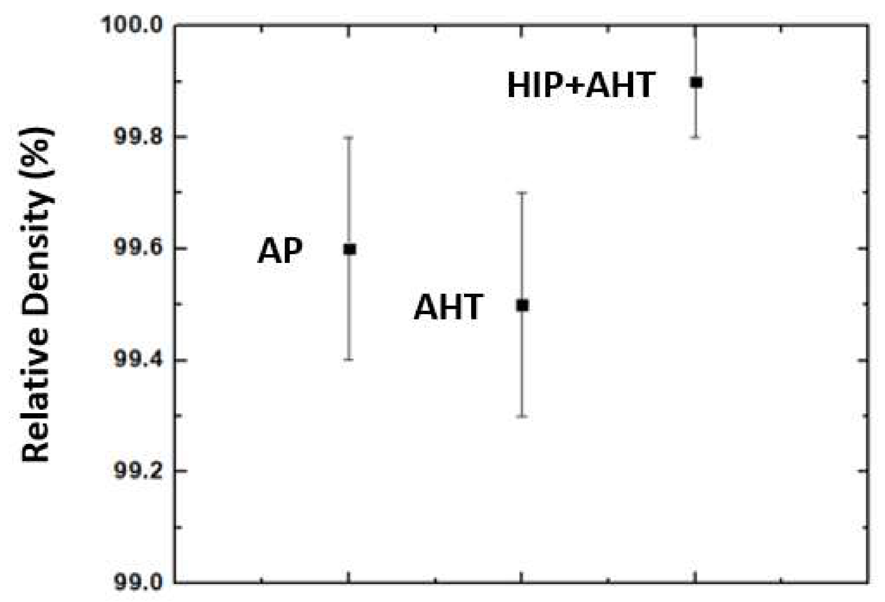
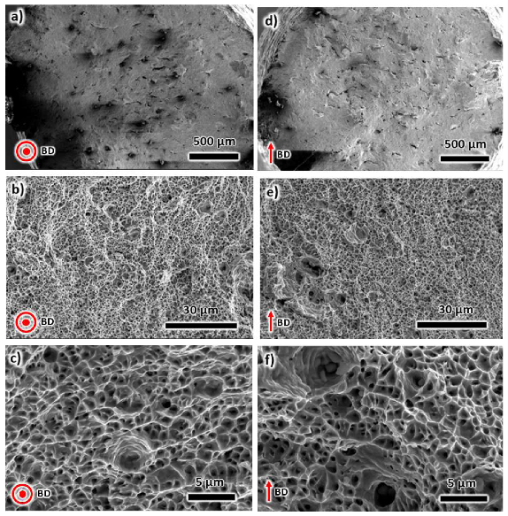
3.3. Microstructural Evolution after Hot Isostatic Pressing and Annealing Heat Treatment (HIP + AHT)

The electron microscopy images of the sample after hot isostatic pressing followed by annealing heat treatment are depicted in Figure 7a,b. The morphology of the grains is completely different than that of the AP and AHT samples in Figure 3; Figure 5, respectively. Polygon-shaped grains with sizes of up to 100 μm can be observed. It also appears that there may be micro-scale twins that developed as a result of the applied pressure during the HIP process. The nano-scale twin-like structure, similar to that of the AHT sample, is also evident.
Similar to that of the microstructure of the AHT sample, the presence of precipitates in the SEM images is evident (see red arrows). However, note that the precipitates in the HIP + AHT sample are not constrained to grain boundaries. It appears that the precipitates are more homogeneously distributed in the microstructure. Note that the HIP process generates dislocation density inside the grains, which can act as nucleation sites of precipitation during the high-temperature post-processing treatment.
To better understand the microstructures, EBSD analysis was performed on the HIP + AHT sample. The results are presented in Figure 8. The EBSD map in the BD direction confirms the polygonal morphology of the grains in the SEM image above (Figure 8a). There is also a significant fraction of twins as a result of the applied pressure during the HIP. Interestingly, the fraction of LAGBs was only 2.3% (Figure 8b). The two-stage heat treatment process at 1163 °C and 900 °C assisted in the annihilation of dislocations that were generated after printing. At an elevated temperature, the application of pressure, combined with the inherent residual stress due to printing, can induce the static and dynamic recrystallization [47] of austenitic grains. This phenomenon is depicted by a fine grain size (<10 μm). The general texture in the BD was also obtained using an IPF representation (Figure 8c). The texture intensity factor (2.45) is higher than that of the AP and AHT samples in the BD, but the microstructure still possesses a reasonably random texture. This might be due to the applied pressure that may lead to a slight rotation of grains. The deformation allows rotation of the crystal structure, which results in a higher texture intensity factor. The highest intensity has a (213) orientation.
EBSD analysis was also performed in the TD section, and the EBSD map is presented in Figure 8d. Both the BD and TD sections have a similar grain morphology; thus, it resembles a material with isotropic properties. The fraction of LAGBs is significantly higher than that of the BD, which is 21.1%. Still, this number is significantly lower than the measurements taken from the AP and AHT samples. The general crystallographic texture was also calculated (see Figure 8f), in which the highest intensity has a (101) orientation. However, the texture intensity factor is low (1.89); thus, the microstructure resembles randomly oriented grains.

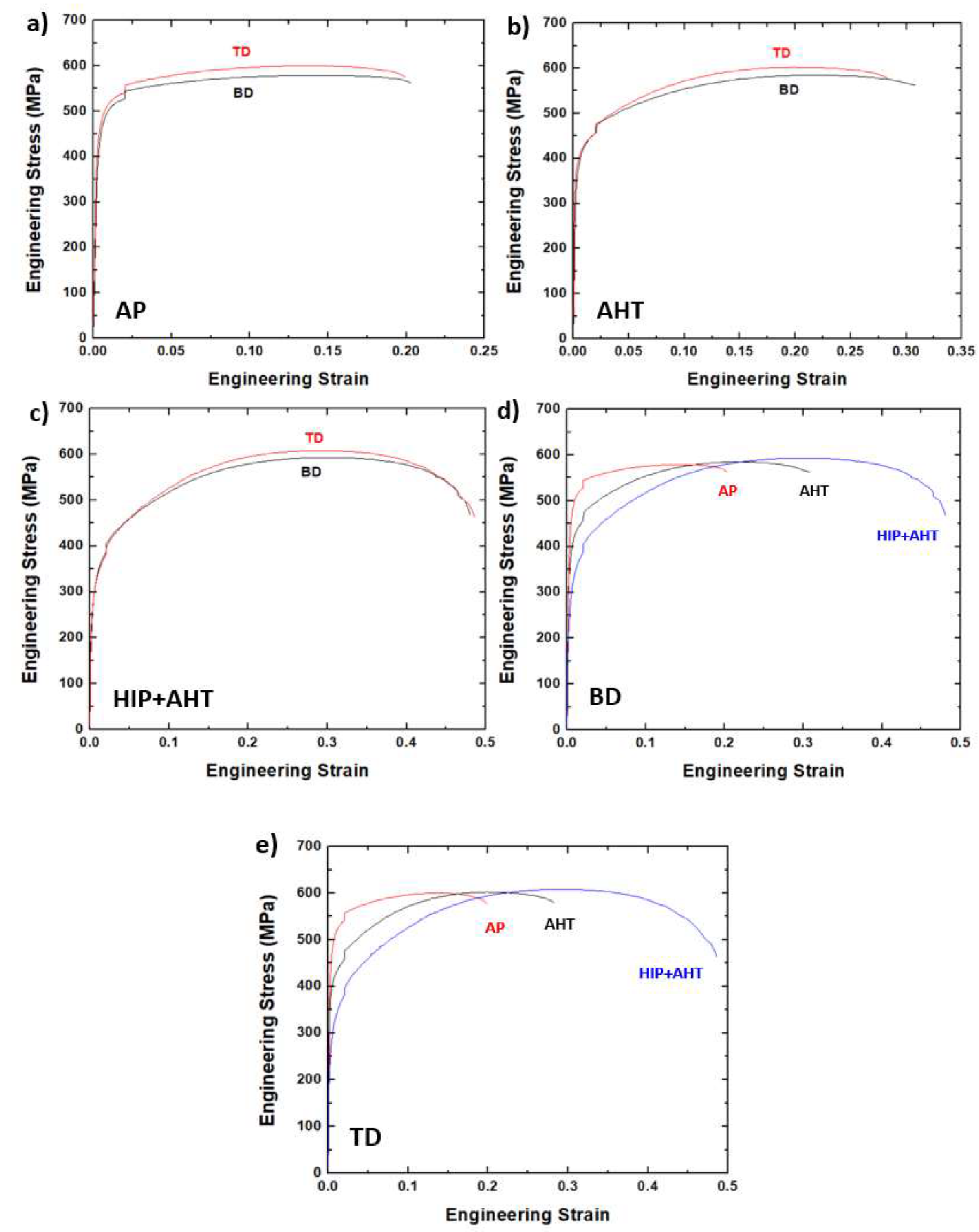
3.4. Mechanical Properties of the Three Conditions

The effects of post-processing heat treatment on the yield strength, tensile strength and the ductility of additively manufactured 316L stainless steel were evaluated via tensile stress–strain curves (Figure 9). A representative of the curve from multiple measurements was shown here since the measured mechanical properties have less than a 3% difference. In Figure 9a, the stress–strain curves of the as-printed sample along the BD and TD are presented. It is well known that the tensile strength along the TD was higher than that of the BD due to the epitaxial grain growth along the BD [48]. Although the present results validate the observations in the literature: the difference between their tensile strengths is only about 1%. The TD has a tensile strength of 585 ± 20 MPa, while the BD has a tensile strength of 579 ± 10 MPa. The elongations of both directions are 21% ± 2%. The yield strengths at TD and BD are 445 ± 20 MPa and 439 ± 5 MPa, respectively. Although the former has a slightly higher value, the numbers are comparable.
After annealing heat treatment, the tensile strengths along the TD and BD are 595 ± 10 MPa and 582 ± 5 MPa, respectively (see Figure 9b). As expected, the tensile strength along the TD is higher by about 2%. Both directions have comparable elongations: 29 ± 2% and 31 ± 3% for TD and BD, respectively. Similarly, the yield strengths are 370 ± 10 MPa (TD) and 365 ± 10 MPa (BD). In general, the ductility significantly increased by about 45% without any compromise in tensile strength. However, the yield strength decreased by approximately 15%.
The mechanical properties after hot isostatic pressing and annealing heat treatment were also measured (Figure 9c). Similar to the AP and AHT samples, the tensile strength of the HIP + AHT sample along the TD (611 ± 5 MPa) was slightly higher than the BD (592 ± 5 MPa) by about 3%. The elongations were comparable in both directions, 48 ± 3% and 47 ± 3% along the TD and BD, respectively. The yield strengths are 263 ± 5 MPa (TD) and 257 ± 5 MPa (BD). In this sample, the ductility increased significantly by approximately 130% as compared to the AP sample. The increase in ductility was also coupled with a slight increase in tensile strength by about 4%. This sample clearly overcomes the strength-to-ductility trade-off in material science [49]. However, note that the yield strength of the HIP + AHT sample led to a decrease of about 40%. Still, the benefit of increasing both the tensile strength and ductility is considered to be beneficial in designing components using additively manufactured alloys. Based on the SEM and EBSD images above, it appears that the presence of both nano-scale and micro-scale twins played a role in improving the ductility of the HIP + AHT sample.
A comparison of the mechanical properties between the AP, AHT, and the HIP + AHT samples is presented in Figure 9d,e for BD and TD, respectively. It can be directly observed that the tensile strengths of all the samples are similar. However, the ductility of the HIP + AHT sample is superior to those of the AP and AHT samples. The slope of the elastic region (modulus of elasticity) significantly changes after post-processing. For example, along the BD, the modulus of elasticity was initially 183 GPa after printing; then, it decreased to 166 GPa after AHT. The modulus of elasticity further decreased after HIP and AHT, from 183 to 150 GPa. The same trend was observed in the measurements along the TD, see Figure 9e.
The mechanical properties acquired from this work are summarized in Table 2. The raw data are presented in Table A1 in the Appendix A section. The standard deviation from five measurements was taken and these were accounted for as an experimental error.
The mechanical properties obtained from this work were then compared with other similar works employing HIP to additively manufactured (via LPBF) 316L stainless steel, as shown in Table 3. It can be observed that the tensile strength of the HIP samples from Lavery et al. [33], Saiedi [50], and Röttger et al. [32] were 542, 570 and 563 MPa. The present work (HIP + AHT) attained a maximum value of 611 MPa, at least 7% higher than the selected literature values that employed HIP alone. The yield strength of the present work was also the highest, which is around 263 MPa (14% higher). The elongation in this work (48%) was comparable to that of the literature values, though it is inferior to the values obtained by Röttger et al. [32], who reported an elongation of 81%.
The fractured surface of the AP sample after tensile testing was characterized using electron microscopy (Figure 10). Three different magnifications were used for fractography in order to provide general and local features of the fractured surface. Figure 10a–c is associated with tests along the BD. In the lowest magnification image (Figure 10a), the scan tracks and layers during printing are evident, as shown by the overlapping linear strips on the cross-section of the fractured surface. The stress applied along the building direction results in poor intralayer fusion, which then leads to fracture. In the high magnification imaging in Figure 10b,c, a combination of dimple structure and cleavage structure can be observed since the material has an appreciable elongation of about 21%. The observations in the BD direction are similar to the fractured surface found in the TD (Figure 10d–f).
Fractography was also performed on the AHT sample (Figure 11). Figure 11a–c is for the fractured surfaces from the tensile tests along the BD, while Figure 11d–f are for the TD. The lower magnification images (Figure 11a,d) display the scan tracks and layers that become unstable during testing. The higher magnification images in Figure 11b,c (BD), and Figure 11e,f (TD) show a significantly higher amount of dimple structure as compared to the AP sample in Figure 10. This observation is due to the improved elongation of the AHT sample (30%) compared to the AP sample (21%).
The SEM images in Figure 12 depict the fractured surface of the HIP + AHT sample after the tensile testing. The first three images (Figure 12a–c) are for the tests along the BD, while the last three micrographs (Figure 12d–f) are for the tests along the TD. The low magnification images in Figure 12a (BD) and Figure 12d (TD) have different features than that of the AP and AHT samples. Here, there are no unstable layers of material that can lead to premature failure. Since the HIP + AHT sample has a lower porosity, the fractured surface illustrates a denser surface after failure. By having a lower fraction of porosity, it allows for the delay of the coalescence of voids to form cracks that eventually propagate until fracture. As a result, this sample had the highest elongation (46%). The high magnification SEM images in Figure 12b,c and Figure 12e,f for the BD and TD, respectively, demonstrate mostly dimple structures, which is common for materials with high ductility. Note that the dimple structures in this sample are far more evident compared to the microstructures in Figure 10 (AP sample) and Figure 11 (AHT sample).
The deformed samples were analyzed via EBSD to understand the behavior of grains during straining. The results for the AP, AHT and the HIP + AHT samples are presented in Figure 13a–c, respectively. Note that the BD is parallel to the tensile direction. The tensile direction is along the vertical direction of the image. As expected, the grains become elongated as a result of applied stress. The deformation allows the formation of twins in the AP (Figure 13a) and the AHT (Figure 13b) samples, which commonly occurs in both additively and conventionally manufactured 316L stainless steel [51]. However, for the HIP + AHT sample that has twins prior to tensile testing, the twins are less evident. This may be due to the rotation of crystals during deformation at a preferred orientation. For this reason, the IPF configuration is presented alongside the EBSD images. Here it can be seen that the texture intensity factor increases, i.e., from 2.68 to 6.47, as the elongation increases, i.e., from 21% to 48%. The (111) planes become more evident during deformation. Note that the increase in elongation allows for more crystal orientation during deformation; thus, the textured material is depicted in Figure 13c, with an intensity factor of 6.47 and a preferred (111) orientation.

4. Conclusions

In this work, LPBF-manufactured samples of 316L stainless steel were hot isostatically pressed and annealed. The effect of annealing heat treatment on the microstructure, porosity, mechanical properties and fracture behavior was investigated. The combination of hot isostatic pressing and annealing heat treatment significantly improved the ductility of the as-printed 316L stainless steel by as much as 130% without sacrificing tensile strength. The presence of nano-scale and macro-scale twins appears to contribute to the improved ductility of the material. Despite the improved elongation, this value is within the average values obtained from the literature that only employed HIP. The main advantage of the present method is the increase in yield and tensile strengths by at least 14% and 7%, respectively, from values cited in the literature. Since one of the issues in certifying AM components is the limited information concerning mechanical properties, this work provides additional post-processing data following HIP. This contributes to our knowledge of the yield and tensile strengths of AM 316L stainless steel components. Fracture surface analysis reveals that hot isostatic pressing and annealing heat treatment modifies the fracture mechanism of the material. This post-processing technique facilitates the enhanced ductile failure of 316L stainless steel.

Author Contributions

Conceptualization, C.A.J., Y.T. and K.C.; methodology, Y.T. C.A.J. and K.C.; software, C.A.J. and K.C.; validation, Y.T., C.A.J. and J.G.S.; formal analysis, K.C.; investigation, C.A.J., Y.T., J.G.S. and K.C.; resources, C.A.J., Y.T. and J.G.S.; data curation, K.C.; writing—original draft preparation, K.C., Y.T. and C.A.J.; writing—review and editing, C.A.J., Y.T., and J.G.S.; visualization, C.A.J. and K.C.; supervision, C.A.J.; project administration, C.A.J.; funding acquisition, C.A.J. All authors have read and agreed to the published version of the manuscript.

Funding

This research was funded by the Natural Sciences and Engineering Research Council of Canada (NSERC), the Canada Foundation for Innovation (CFI), the New Brunswick Innovation Foundation (NBIF) and the Harrison McCain Foundation.

Conflicts of Interest

The authors declare no conflict of interest.

Appendix A. Raw Data Used in the Values of Mechanical Properties in Table 2

Table A1 below summarizes the obtained elongation, yield strength, and the tensile strengths from five measurements along the TD and the BD:
Table A1. Measured mechanical properties along the BD and the TD of the AP, AHT and the HIP + AHT samples.
SampleYield Strength, MPaTensile Strength, MPaElongation, %
TDBDTDBDTDBD
AP-146044558857717.720.3
AP-243143358658421.118.7
AP-346543960358022.222.8
AP-445244159658822.723.0
AP-541843755256522.820.6
AHT-136535761157930.326.6
AHT-237335759457628.634.2
AHT-335537959858427.832.7
AHT-437536558358827.031.3
AHT-538036859158133.029
HIP-AHT-125625760759750.044.4
HIP-AHT-226325860559851.251.0
HIP-AHT-326926161158644.443.3
HIP-AHT-426524961658945.146.3
HIP-AHT-526026161858950.250.3

References

  1. Kruth, J.-P.; Leu, M.-C.; Nakagawa, T. Progress in additive manufacturing and rapid prototyping. Cirp Ann. Manuf. Technol. 1998, 47, 525–540. [Google Scholar] [CrossRef]
  2. Tian, Y.; McAllister, D.; Colijn, H.; Mills, M.; Farson, D.; Nordin, M.; Babu, S. Rationalization of microstructure heterogeneity in INCONEL 718 builds made by the direct laser additive manufacturing process. Metall. Mater. Trans. A 2014, 45, 4470–4483. [Google Scholar] [CrossRef]
  3. Fayazfar, H.; Salarian, M.; Rogalsky, A.; Sarker, D.; Russo, P.; Paserin, V.; Toyserkani, E. A critical review of powder-based additive manufacturing of ferrous alloys: Process parameters, microstructure and mechanical properties. Mater. Des. 2018, 144, 98–128. [Google Scholar] [CrossRef]
  4. Astm, I. ASTM52900-15 Standard Terminology for Additive Manufacturing—General Principles—Terminology. ASTM Int. West Conshohockenpa 2015, 3, 5. [Google Scholar]
  5. Niendorf, T.; Brenne, F.; Schaper, M. Lattice Structures Manufactured by SLM: On the Effect of Geometrical Dimensions on Microstructure Evolution During Processing. Metall. Mater. Trans. B 2014, 45, 1181–1185. [Google Scholar] [CrossRef]
  6. Kantareddy, S.; Roh, B.; Simpson, T.; Joshi, S.; Dickman, C.; Lehtihet, E. Saving weight with metallic lattice structures: Design challenges with a real-world example. In Proceedings of the Solid Freeform Fabrication Symposium (SFF), Austin, TX, USA, 13–15 August 2020; pp. 8–10. [Google Scholar]
  7. Muñiz-Lerma, J.A.; Tian, Y.; Wang, X.; Gauvin, R.; Brochu, M. Microstructure evolution of Inconel 738 fabricated by pulsed laser powder bed fusion. Prog. Addit. Manuf. 2019, 4, 97–107. [Google Scholar] [CrossRef]
  8. Tian, Y.; Muñiz-Lerma, J.; Brochu, M. Nickel-based superalloy microstructure obtained by pulsed laser powder bed fusion. Mater. Charact. 2017, 131, 306–315. [Google Scholar] [CrossRef]
  9. Xiao, L.; Song, W. Additively-manufactured functionally graded Ti-6Al-4V lattice structures with high strength under static and dynamic loading: Experiments. Int. J. Impact Eng. 2018, 111, 255–272. [Google Scholar] [CrossRef]
  10. Palanivel, S.; Dutt, A.K.; Faierson, E.J.; Mishra, R.S. Spatially dependent properties in a laser additive manufactured Ti–6Al–4V component. Mater. Sci. Eng. A 2016, 654, 39–52. [Google Scholar] [CrossRef]
  11. Maskery, I.; Aboulkhair, N.T.; Aremu, A.O.; Tuck, C.J.; Ashcroft, I.A.; Wildman, R.D.; Hague, R.J.M. A mechanical property evaluation of graded density Al-Si10-Mg lattice structures manufactured by selective laser melting. Mater. Sci. Eng. A 2016, 670, 264–274. [Google Scholar] [CrossRef] [Green Version]
  12. Delroisse, P.; Jacques, P.J.; Maire, E.; Rigo, O.; Simar, A. Effect of strut orientation on the microstructure heterogeneities in AlSi10Mg lattices processed by selective laser melting. Scr. Mater. 2017, 141, 32–35. [Google Scholar] [CrossRef]
  13. Tian, R.P.; Aranas, C., Jr. Microstructural evolution and mechanical properties of a newly designed steel fabricated by laser powder bed fusion. Addit. Manuf. 2020. submitted. [Google Scholar]
  14. Palad, Y.T.; Chadha, K.; Rodrigues, S.; Aranas, C., Jr. Microstructural of a newly designed steel manufactured by laser powder bed fusion. Mater. Lett. (in press).
  15. Wang, X.; Muñiz-Lerma, J.; Sanchez-Mata, O.; Shandiz, M.A.; Brodusch, N.; Gauvin, R.; Brochu, M. Characterization of single crystalline austenitic stainless steel thin struts processed by laser powder bed fusion. Scr. Mater. 2019, 163, 51–56. [Google Scholar] [CrossRef]
  16. Chadha, K.; Tian, Y.; Bocher, P.; Spray, J.G.; Aranas, C. Microstructure Evolution, Mechanical Properties and Deformation Behavior of an Additively Manufactured Maraging Steel. Materials 2020, 13, 2380. [Google Scholar] [CrossRef] [PubMed]
  17. Popovich, A.; Sufiiarov, V.; Polozov, I.; Borisov, E.; Masaylo, D.; Orlov, A. Microstructure and mechanical properties of additive manufactured copper alloy. Mater. Lett. 2016, 179, 38–41. [Google Scholar] [CrossRef]
  18. Kazemi, H.; Miller, D.; Mohan, A.; Griffith, Z.; Jin, Y.; Kwiatkowski, J.; Tran, L.; Crawford, M. 350mW G-band medium power amplifier fabricated through a new method of 3D-copper additive manufacturing. In Proceedings of the 2015 IEEE MTT-S International Microwave Symposium, Phoenix, AZ, USA, 17–22 May 2015; pp. 1–3. [Google Scholar]
  19. Nilsén, F.; Ituarte, I.F.; Salmi, M.; Partanen, J.; Hannula, S.P. Effect of process parameters on non-modulated Ni-Mn-Ga alloy manufactured using powder bed fusion. Addit. Manuf. 2019, 28, 262–274. [Google Scholar] [CrossRef] [Green Version]
  20. Ituarte, I.F.; Salmi, M.; Papula, S.; Huuki, J.; Hemming, B.; Coatanea, E.; Nurmi, S.; Virkkunen, I. Surface modification of additively manufactured 18% nickel maraging steel by ultrasonic vibration-assisted ball burnishing. J. Manuf. Process. 2020, 142, 071008. [Google Scholar] [CrossRef]
  21. Singh, S.; Ramakrishna, S.; Singh, R. Material issues in additive manufacturing: A review. J. Manuf. Process. 2017, 25, 185–200. [Google Scholar] [CrossRef]
  22. Yan, F.K.; Liu, G.Z.; Tao, N.R.; Lu, K. Strength and ductility of 316L austenitic stainless steel strengthened by nano-scale twin bundles. Acta Mater. 2012, 60, 1059–1071. [Google Scholar] [CrossRef]
  23. Zhong, Y.; Liu, L.; Wikman, S.; Cui, D.; Shen, Z. Intragranular cellular segregation network structure strengthening 316L stainless steel prepared by selective laser melting. J. Nucl. Mater. 2016, 470, 170–178. [Google Scholar] [CrossRef]
  24. Shamsujjoha, M.; Agnew, S.R.; Fitz-Gerald, J.M.; Moore, W.R.; Newman, T.A. High Strength and Ductility of Additively Manufactured 316L Stainless Steel Explained. Metall. Mater. Trans. A 2018, 49, 3011–3027. [Google Scholar] [CrossRef]
  25. Wang, X.; Muñiz-Lerma, J.A.; Sánchez-Mata, O.; Shandiz, M.A.; Brochu, M. Microstructure and mechanical properties of stainless steel 316L vertical struts manufactured by laser powder bed fusion process. Mater. Sci. Eng. A 2018, 736, 27–40. [Google Scholar] [CrossRef]
  26. Wang, X.; Muñiz-Lerma, J.A.; Shandiz, M.A.; Sanchez-Mata, O.; Brochu, M. Crystallographic-orientation-dependent tensile behaviours of stainless steel 316L fabricated by laser powder bed fusion. Mater. Sci. Eng. A 2019, 766, 138395. [Google Scholar] [CrossRef]
  27. Köhnen, P.; Haase, C.; Bültmann, J.; Ziegler, S.; Schleifenbaum, J.H.; Bleck, W. Mechanical properties and deformation behavior of additively manufactured lattice structures of stainless steel. Mater. Des. 2018, 145, 205–217. [Google Scholar] [CrossRef]
  28. Sun, Z.; Tan, X.; Tor, S.B.; Chua, C.K. Simultaneously enhanced strength and ductility for 3D-printed stainless steel 316L by selective laser melting. NPG Asia Mater. 2018, 10, 127–136. [Google Scholar] [CrossRef]
  29. Karaman, I.; Sehitoglu, H.; Maier, H.J.; Chumlyakov, Y.I. Competing mechanisms and modeling of deformation in austenitic stainless steel single crystals with and without nitrogen. Acta Mater. 2001, 49, 3919–3933. [Google Scholar] [CrossRef]
  30. Yadollahi, A.; Shamsaei, N.; Thompson, S.M.; Seely, D.W. Effects of process time interval and heat treatment on the mechanical and microstructural properties of direct laser deposited 316L stainless steel. Mater. Sci. Eng. A 2015, 644, 171–183. [Google Scholar] [CrossRef]
  31. Blinn, B.; Klein, M.; Gläßner, C.; Smaga, M.; Aurich, J.C.; Beck, T. An Investigation of the Microstructure and Fatigue Behavior of Additively Manufactured AISI 316L Stainless Steel with Regard to the Influence of Heat Treatment. Metals 2018, 8, 220. [Google Scholar] [CrossRef] [Green Version]
  32. Rottger, A.; Geenen, K.; Windmann, M.; Binner, F.; Theisen, W. Comparison of microstructure and mechanical properties of 316L austenitic steel processed by selective laser melting with hot-isostatic pressed and cast material. Mater. Sci. Eng. A 2016, 678, 365–376. [Google Scholar] [CrossRef]
  33. Lavery, N.P.; Cherry, J.; Mehmood, S.; Davies, H.; Girling, B.; Sackett, E.; Brown, S.G.R.; Sienz, J. Effects of hot isostatic pressing on the elastic modulus and tensile properties of 316L parts made by powder bed laser fusion. Mater. Sci. Eng. A 2017, 693, 186–213. [Google Scholar] [CrossRef] [Green Version]
  34. Montero-Sistiaga, K.L.; Godino-Martinez, M.; Boschmans, K.; Kruth, J.P.; Humbeeck, J.V.; Vanmeensel, K. Microstructure evolution of 316L produced by HP-SLM (high power selective laser melting). Addit. Manuf. 2018, 23, 402–410. [Google Scholar] [CrossRef]
  35. Geenen, K.; Rottger, A.; Theisen, W. Corrosion behavior of 316L austenitic steel processed by selective laser melting, hot-isostatic pressing and casting. Mater. Corros. 2017, 68, 764–775. [Google Scholar] [CrossRef]
  36. AlMangour, B.; Grzesiak, D.; Yang, J.M. Selective laser melting of TiB2/316L stainless steel composites: The roles of powder preparation and hot isostatic pressing post-treatment. Powder Technol. 2017, 309, 37–48. [Google Scholar] [CrossRef]
  37. Wang, Z.; Shi, Y.; Li, R.; Wei, Q.; Liu, J. Manufacturing AISI316L components via selective laser melting coupled with hot isostatic pressing. Mater. Sci. Forum 2011, 675–677, 853–856. [Google Scholar] [CrossRef]
  38. Liverani, E.; Toschi, S.; Ceschini, L.; Fortunato, A. Effect of selective laser melting (SLM) process parameters on microstructure and mechanical properties of 316L austenitic stainless steel. J. Mater. Process. Technol. 2017, 249, 255–263. [Google Scholar] [CrossRef]
  39. Rashid, R.; Masood, S.H.; Ruan, D.; Palanisamy, S.; Rahman Rashid, R.A.; Brandt, M. Effect of scan strategy on density and metallurgical properties of 17-4PH parts printed by Selective Laser Melting (SLM). J. Mater. Process. Technol. 2017, 249, 502–511. [Google Scholar] [CrossRef]
  40. Paul, C.P.; Ganesh, P.; Mishra, S.; Bhargava, P.; Negi, J.; Nath, A. Investigating laser rapid manufacturing for Inconel-625 components. Opt. Laser Technol. 2007, 39, 800–805. [Google Scholar] [CrossRef]
  41. Thijs, L.; Sistiaga, M.L.M.; Wauthle, R.; Xie, Q.; Kruth, J.-P.; Van Humbeeck, J. Strong morphological and crystallographic texture and resulting yield strength anisotropy in selective laser melted tantalum. Acta Mater. 2013, 61, 4657–4668. [Google Scholar] [CrossRef] [Green Version]
  42. He, B.; Hu, B.; Yen, H.; Cheng, G.; Wang, Z.; Luo, H.; Huang, M. High dislocation density–induced large ductility in deformed and partitioned steels. Science 2017, 357, 1029–1032. [Google Scholar] [CrossRef] [PubMed] [Green Version]
  43. Attallah, M.M.; Jennings, R.; Wang, X.; Carter, L.N. Additive manufacturing of Ni-based superalloys: The outstanding issues. MRS Bull. 2016, 41, 758–764. [Google Scholar] [CrossRef]
  44. Vora, P.; Mumtaz, K.; Todd, I.; Hopkinson, N. AlSi12 in-situ alloy formation and residual stress reduction using anchorless selective laser melting. Addit. Manuf. 2015, 7, 12–19. [Google Scholar] [CrossRef] [Green Version]
  45. Wang, Y.M.; Voisin, T.; McKeown, J.T.; Ye, J.; Calta, N.P.; Li, Z.; Zeng, Z.; Zhang, Y.; Chen, W.; Roehling, T.T.; et al. Additively manufactured hierarchical stainless steels with high strength and ductility. Nat. Mater. 2018, 17, 63–71. [Google Scholar] [CrossRef] [Green Version]
  46. Tan, L.; Allen, T.R.; Busby, J.T. Grain boundary engineering for structure materials of nuclear reactors. J. Nucl. Mater. 2013, 441, 661–666. [Google Scholar] [CrossRef] [Green Version]
  47. Kaspar, R.; Distl, J.S.; Pawelski, O. Extreme austenite grain refinement due to dynamic recrystallization. Steel Res. 1988, 59, 421–425. [Google Scholar] [CrossRef]
  48. Debroy, T.; Wei, H.L.; Zuback, J.S.; Mukherjee, T.; Elmer, J.W.; Milewski, J.O.; Beese, A.M.; Wilson-Heid, A.; De, A.; Zhang, W. Additive manufacturing of metallic components - process, structure and properties. Prog. Mater. Sci. 2018, 92, 112–224. [Google Scholar] [CrossRef]
  49. Jourani, A.; Bouvier, S. Friction and wear mechanisms of 316L stainless steel in dry sliding contact: Effect of abrasive particle size. Tribol. Trans. 2015, 58, 131–139. [Google Scholar] [CrossRef]
  50. Saeidi, K. Stainless Steels Fabricated by Laser Melting: Scaled-down Structural Hierarchies and Microstructural Heterogeneities. Ph.D. Thesis, Stockholm University, Stockholm, Sweden, 2016. [Google Scholar]
  51. Segura, I.; Murr, L.; Terrazas, C.; Bermudez, D.; Mireles, J.; Injeti, V.; Li, K.; Yu, B.; Misra, R.; Wicker, R. Grain boundary and microstructure engineering of Inconel 690 cladding on stainless-steel 316L using electron-beam powder bed fusion additive manufacturing. J. Mater. Sci. Technol. 2019, 35, 351–367. [Google Scholar] [CrossRef]
Figure 1. (a) Scanning electron microscope image of the 316L powder; and (b) the powder size distribution. Q3 refers to the cumulative size distribution while q3 indicates the particle size distribution. The diameter of the powders was mostly in the range of 15–25 μm.
Metals 10 00753 g001
Figure 2. The measured relative densities from the optical micrographs reveal that the hot isostatic pressing (HIP) + annealing heat-treated (AHT) sample has the highest relative density. (n = 5).
Metals 10 00753 g002
Figure 3. Scanning electron microscopy images of the as-printed 316L sample taken from the plane normal to the building direction (BD) at (a) a lower magnification, and (b) at a higher magnification.
Metals 10 00753 g003
Figure 4. The (a) electron backscatter diffraction (EBSD) inverse pole figure (IPF)-Z map, (b) the grain boundary distribution map, and (c) the IPF representation of grains of as-printed 316L samples taken from the building direction. Similarly, the (d) EBSD IPF-Z map, (e) the grain boundary distribution map, and (f) the IPF representation of grains of as-printed 316L samples taken from the transverse direction.
Metals 10 00753 g004
Figure 5. Scanning electron microscopy images of the heat-treated 316L sample taken from the plane normal to the building direction at (a) low magnification, and (b) high magnification.
Metals 10 00753 g005
Figure 6. The (a) EBSD IPF-Z map, (b) the grain boundary distribution map, and (c) the IPF representation of the grains of annealing heat-treated 316L samples taken from the building direction. Similarly, the (d) EBSD IPF-Z map, (e) the grain boundary distribution map, and (f) the IPF representation of the grains of the annealing heat-treated samples taken from the transverse direction.
Metals 10 00753 g006
Figure 7. The scanning electron microscopy images of the 316L sample after hot isostatic pressing and annealing heat treatment at (a) lower magnification, and (b) higher magnification.
Metals 10 00753 g007
Figure 8. The (a) EBSD IPF-Z map, (b) the grain boundary distribution map, and (c) the IPF representation of the grains of hot isostatic pressing and annealing heat treatment taken from the building direction. Similarly, the (d) EBSD IPF-Z map, (e) the grain boundary distribution map, and (f) the IPF representation of the grains of the sample after hot isostatic pressing and annealing heat treatment taken from the transverse direction.
Metals 10 00753 g008
Figure 9. The engineering stress–strain curves of (a) the as-printed (AP) sample, (b) the AHT sample, and (c) the HIP + AHT sample. The stress–strain curves of each condition are compared in (d) the BD, and (e) the transverse direction (TD).
Metals 10 00753 g009
Figure 10. SEM images of the fractured surface of the AP sample tensile tested along the BD (ac), and the TD (df).
Metals 10 00753 g010
Figure 11. SEM images of the annealing heat-treated sample tensile tested along BD (ac) and TD (df).
Metals 10 00753 g011
Figure 12. SEM images of the hot isostatic pressed and annealing heat-treated sample tensile tested along the BD (ac) and the TD (df).
Metals 10 00753 g012
Figure 13. The EBSD IPF-Z map and IPF representation of tensile tested samples: (a) as-printed, (b) annealing heat treated, and (c) hot isostatic pressed and annealing heat treated.
Metals 10 00753 g013
Table 1. Chemical composition (wt%) of the 316L stainless steel powders.
SampleFeCrNiMoMnSiCN
PowderBal.17.313.92.791.510.240.0080.07
BuildBal.16.913.82.561.520.240.0080.05
Table 2. Summary of the mechanical properties of additively manufactured 316L stainless steel. (n = 5).
Mechanical PropertyAP (BD)AP (TD)AHT (BD)AHT (TD)HIP + AHT (BD)HIP + AHT (TD)
Tensile Strength, MPa579 ± 10585 ± 20582 ± 5595 ± 10592 ± 5611 ± 5
Yield Strength, MPa439 ± 5445 ± 20365 ± 10370 ± 10257 ± 5263 ± 5
Elongation, %21 ± 221 ± 231 ± 329 ± 247 ± 348 ± 3
Table 3. Comparison of the results (this work) with the published data on additively manufactured 316L steel.
ReferenceManufacturing HistoryYield Strength, MPaTensile Strength, MPaElongation, %
Lavery [33]As-printed38553422%
Lavery [33]HIP (1125 °C, 137 MPa)22754241%
Saiedi [50]As-printed45670345%
Saiedi [50]Annealed41967451%
Saiedi [50]HIP22057054%
Röttger [32]As-printed427 ± 8522 ± 515 ± 2
Röttger [32]HIP (1150 °C, 150 MPa) 231 ± 4563 ± 681 ± 7
This workAs-printed445 ± 20585 ± 2021 ± 2
This workAnnealed370 ± 10595 ± 1029 ± 2
This workHIP + annealed263 ± 5611 ± 548 ± 3

