Article

Comparative Study on the Dry Sliding Friction Properties of In-Situ Micron and Submicron (Ti-V)C Reinforced Fe-Based Laser Cladding Layers

College of Mechanical and Automotive Engineering, Qilu University of Technology (Shandong Academy of Sciences), Jinan 250353, China
*
Authors to whom correspondence should be addressed.
Metals 2020, 10(6), 742; https://doi.org/10.3390/met10060742
Submission received: 29 April 2020 / Revised: 27 May 2020 / Accepted: 30 May 2020 / Published: 3 June 2020

Abstract

:
By optimising the particle size of cladding alloy powders, in situ micron and submicron (Ti-V)C reinforced Fe-based laser cladding layers were prepared and the dry sliding friction properties were comparatively studied. Results showed that there were same phases of α-Fe, γ, TiC, and TiVC2 in the two cladding layers. The average grain size of the Fe-based matrix was 3.46 μm and 3.37 μm, the microhardness was 731 HV0.2 and 736 HV0.2, and the area ratio of carbides was 11.14% and 11.02%, respectively. The dry sliding wear resistance of the cladding layer reinforced by 1.95 μm carbides was 2.76 times higher than that of the 0.49 μm carbides. The failure mechanism of the cladding layer with the micron carbides was mainly caused by plastic deformation of the cladding layer matrix, whereas that of the submicron carbides involved both the plastic deformation of the cladding layer matrix and the abrasion that was caused by the peeled carbides.

1. Introduction

In the field of surface engineering, laser cladding technology can prepare a cladding layer with a low dilution rate, small stress and deformation, and metallurgical combination with the substrate [1,2,3,4]. Considering performance-price ratio of the cladding materials, Fe-based alloy powders show good application prospects owing to their low cost and high wear resistance [5,6]. However, under severe working conditions, pure Fe-based cladding layers can no longer meet the requirements and carbide (e.g., NbC, TiC, VC, and WC) reinforced Fe-based composite cladding layers have attracted widespread attention [7,8,9,10,11]. Due to the different corrosion potential, there will generate galvanic corrosion between carbides and Fe-based layer matrix in corrosion medium. Reducing carbides size is beneficial to improve the corrosion resistance of cladding layers, but the variation of their wear resistance is worthy of research.
Several studies have confirmed that the wear resistance of a material is directly proportional to its hardness; specifically, the higher the hardness, the better the wear resistance [12,13,14]. However, only a few studies have focused on the effects of the particle size on the wear resistance of carbide-reinforced metal matrix composite materials. Van Acker et al. [15] confirmed that a decrease of the WC particle size could improve the wear resistance of the WC/Ni cladding layer when the WC content was 10%, and it was clear that the wear resistance increased with the overall hardness. Wang et al. [16] found that the dry sliding friction wear rate of WC/Co alloys decreased significantly with decreasing WC particle size due to mitigation of multiple risks caused by plastic deformation, fracture, fragmentation and oxidation of grains. Hardness played an essential role in the wear resistance in this case. Duan et al. [17] indicated that for the Al2O3/Fe-Cr-Mo laser cladding layers, the dry sliding friction wear performance of the 8 wt% nano-Al2O3 cladding layer was better than that of the 8 wt% micron-Al2O3 cladding layer. The nano-Al2O3 improved the hardness of the cladding layer more obviously than micro-Al2O3. The improvement of the wear resistance of these three composite materials is mainly attributed to the increase of their hardness. However, few studies have focused on the effects of particle size of the reinforcing phase on the wear resistance of composite materials that possess a similar hardness. Therefore, in this study, by optimising the particle size of cladding alloy powders under the same processing conditions, in situ micron and submicron (Ti-V)C reinforced Fe-based laser cladding layers that possessed same microstructures and similar hardness were prepared, the aim of the present study was to undertake comparative studies regarding the effects of the (Ti-V)C particle size on the dry sliding friction properties of (Ti-V)C/Fe cladding layers.

2. Experimental Materials and Methods

Fe-based cladding alloy powders were composed of 22.67 wt% FeTi30 (Dingxin wear resistant material Co., Ltd., Xingtai, China), 13.92 wt% FeV50 (Dingxin wear resistant material Co., Ltd., Xingtai, China), 6.24 wt% graphite (Dingxin wear resistant material Co., Ltd., Xingtai, China) and 57.17 wt% reduced iron powder (Dingxin wear resistant material Co., Ltd., Xingtai, China). The particle sizes of the alloy powders are listed in Table 1, and were marked as S1 and S2 respectively. The mixed powder was preset on low carbon steel substrates using a sodium silicate binder and the thickness of the preset layer was approximately 1.0 mm. A diode laser (Laserline LDF-4000, wavelength: 1030 nm, Koblenz, Germany) was used with a laser power of 2050 W, a spot diameter of 4.0 mm, a scanning speed of 5.0 mm/s, and an overlap rate of 25%. The shielded argon gas was 10 L/min.
An X-ray diffractometer (XRD-6100, Shimadzu, Kyoto, Japan) was used for the phase analysis, with a working voltage of 40 kV and current of 150 mA. The microstructure and wear morphologies of the cladding layers were observed using a scanning electron microscope (SUPRA55, Zeiss, Jena, Germany) and an optical microscope (VHX-5000, Keyence, Osaka, Japan). Dry sliding wear tests were performed on the upper surface of the cladding layer with a high-speed reciprocating wear tester (MDW-02, YIHUA, Ji’nan, China), with a load of 30 N, frequency of 3 Hz, and stroke distance of 6 mm. The wear volume was analysed using an 3D texture profile acquisition system (Contour Elite K, BRUKER, Karlsruhe, Germany) for material surfaces. The hardness in the upper surface of the cladding layers were tested by using a hardness tester (HXD-1000TMC, Baihe, Shanghai, China) with a load of 1.96 N, and the holding time was 15 s.

3. Results and Discussions

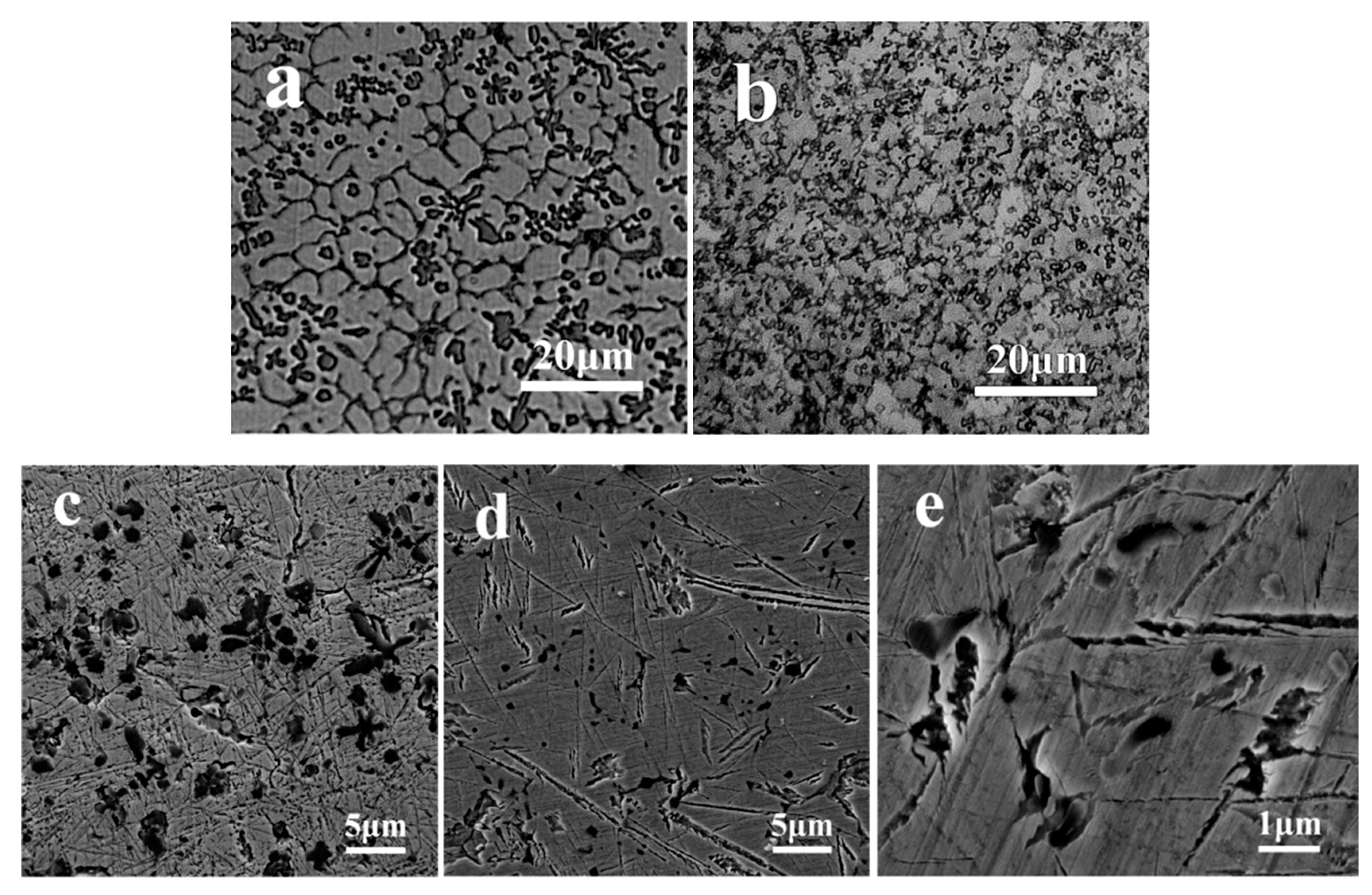
There are diffraction peaks of α-Fe, γ, TiC, and TiVC2 appeared in the X-ray diffraction patterns that shown in Figure 1. It is known that there are same carbides in the two cladding layers. Moreover, it was found that the α-Fe diffraction peaks deviated to a lower angle, indicating that the interplanar spacing of α-Fe was increased [18]. In comprehensive consideration with the Figure 2, the α-Fe can be ascertained as the lath martensite. Therefore, the microstructures of the two cladding layers are lath martensite and retained austenite, indicating that the two cladding layers possessed the same microstructures.
Figure 2 shows micrographs of the cladding layers. The grain sizes of the two cladding layers were similar. From the Figure 2c,d, it can be seen that there are amounts of lath martensite in S1 and S2 cladding layers.
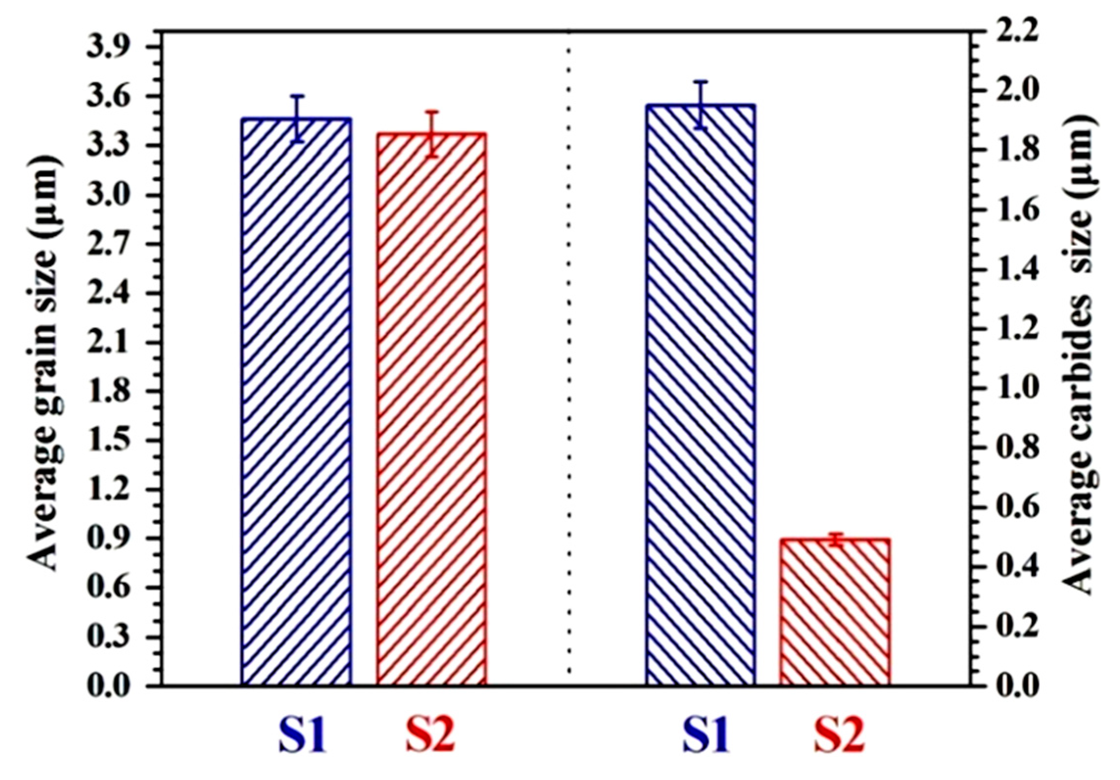
The carbides in S1 were much larger than those in S2, with the average particle sizes of the carbides found to be 1.95 µm and 0.49 µm, respectively. Moreover, the area of the carbides in S1 was 11.14% and that in S2 was 11.02%, which can be inferred that there were same quantities of carbides in the two cladding layers. The average grains size of the cladding layers matrix and the average carbides size are shown in Figure 3. The average grain sizes of the S1 and S2 cladding layer matrix were 3.46 µm and 3.37 µm, respectively.
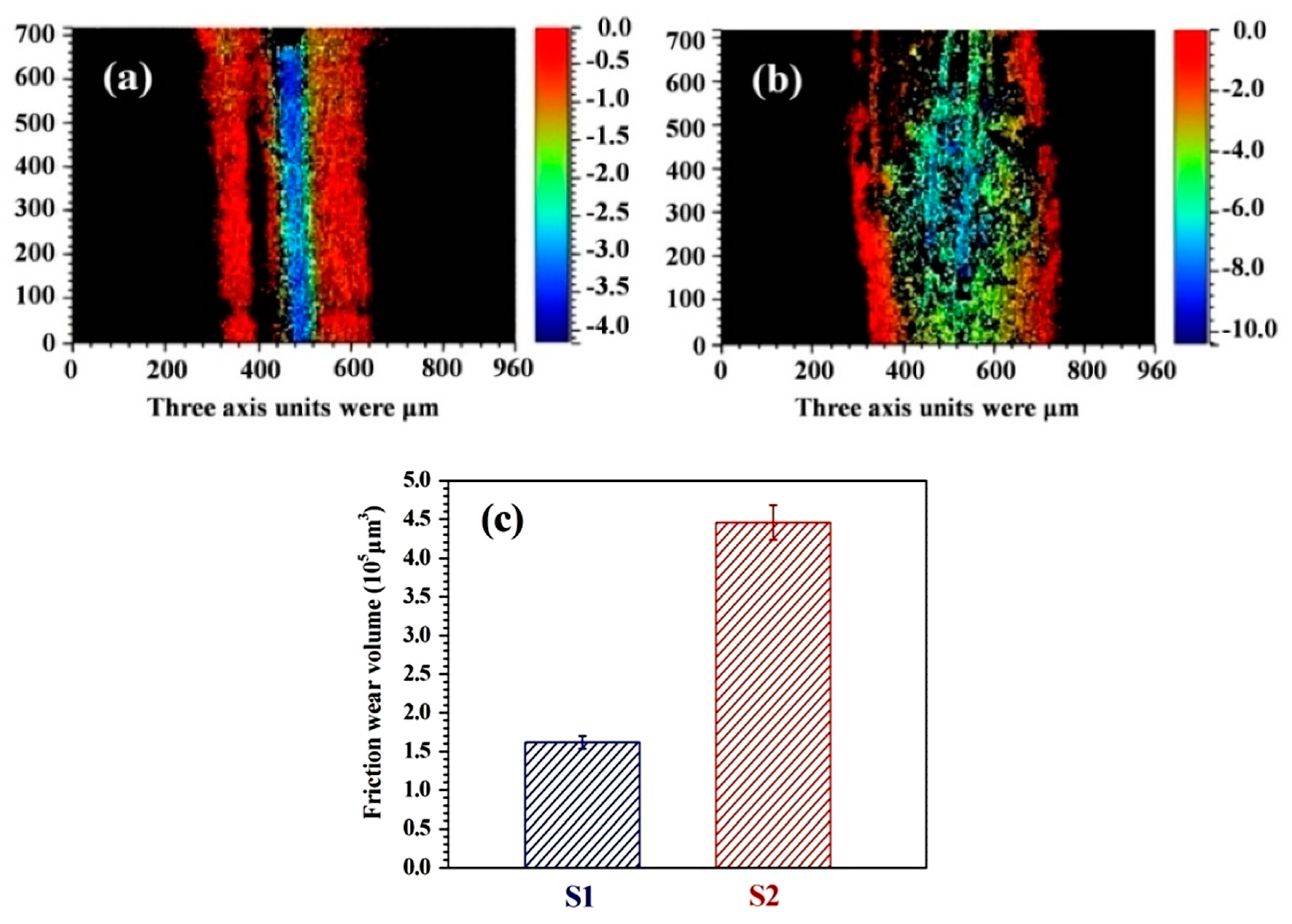
The three-dimensional morphologies of the wear scars and the wear volumes in the two cladding layers are shown in Figure 4. The width and depth of the wear scar in the S2 cladding layer were larger than those in the S1 cladding layer. The wear volumes of S1 and S2 were found to be 161,567 μm3 and 445,770 μm3, respectively; therefore, the wear resistance of the S1 cladding layer was 2.76 times higher than that of the S2 cladding layer.
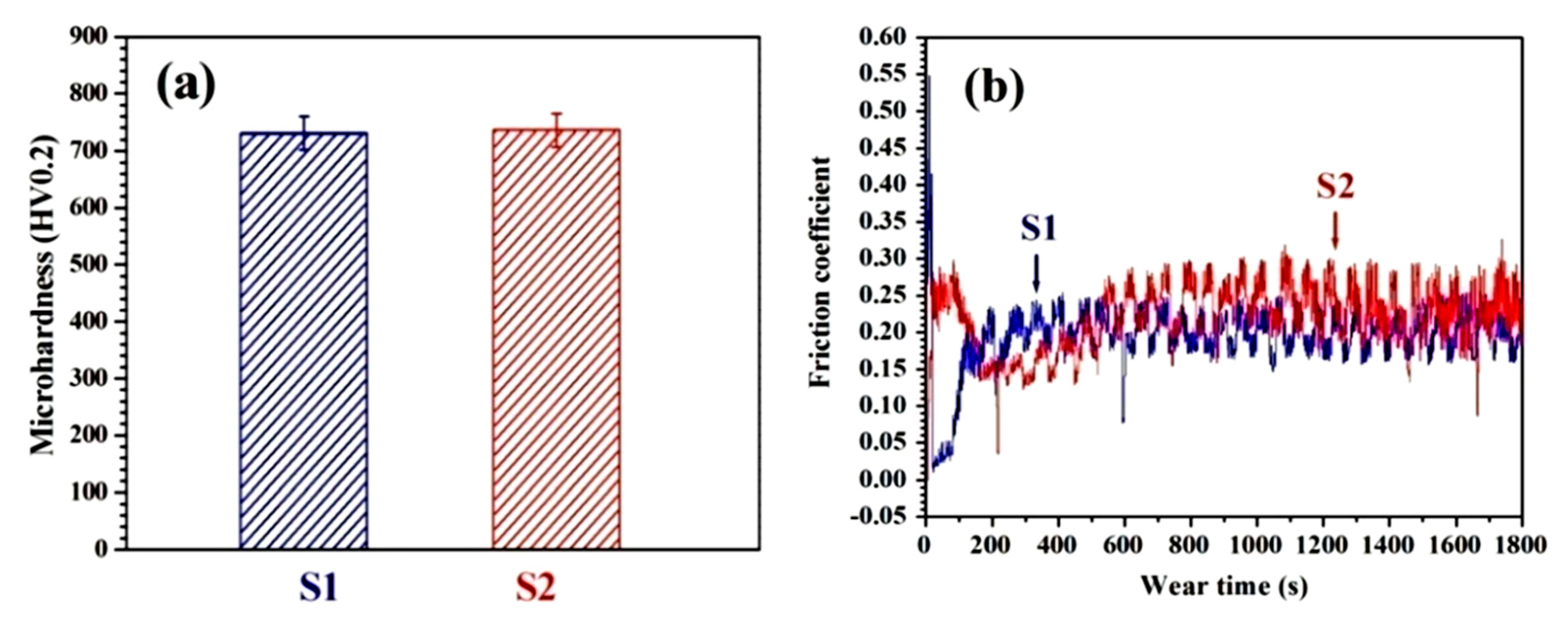
Figure 5 shows the average microhardness on the upper surface and the friction coefficients of the two cladding layers. It can be determined that the average microhardnesses on the upper surface of S1 and S2 were 731 HV0.2 and 736 HV0.2, respectively. The friction coefficients of the two cladding layers were divided into the running-in stage and the stable friction stage. The running-in stage of S1 was shorter than that of S2. During the running-in stage, the friction coefficient of the S2 cladding layer first decreased and then increased. The contact surface between the cladding layer and grinding ball hardened, the roughness became smaller, and the friction coefficient decreased. However, a small component of the cladding layer surface peeled off over time, resulting in an increased roughness and friction coefficient. The stable average friction coefficients of S1 and S2 were 0.202 and 0.236, respectively. In combination with the analysis shown in Figure 6, this might be caused by the accumulation of more debris and particles on the S2 surface, which moved to the connecting surface between the grinding balls and cladding layer, thus causing more severe wear failure.
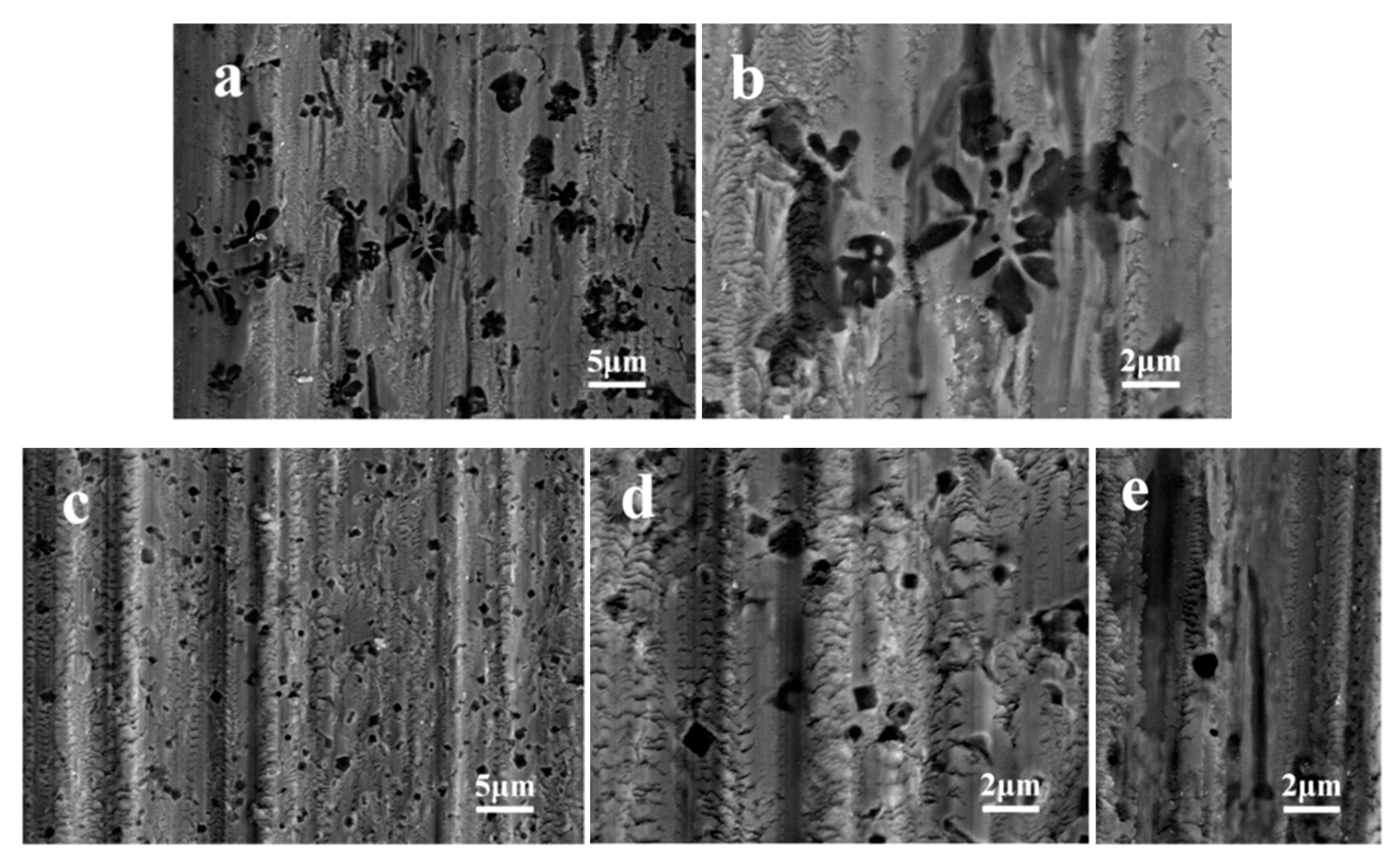
The wear micro-morphologies of the cladding layers are shown in Figure 6. Both the S1 and S2 cladding layers had a step-like wear pattern that was first caused by the plastic deformation of the cladding layer matrix and then the stress concentration accumulated by the dislocation accumulation that caused fracture to occur [19].
There was no peeling phenomenon of the large carbides in the S1 cladding layer, with these acting as the wear-resistant framework; consequently, the surrounding cladding layer matrix did not undergo plastic deformation. The larger carbides embedded more deeply into the layer matrix, which increased the critical stress around them. Thus, the matrix grains of the cladding layer were easily to be removed while suffering from wear. In addition, the abrasive stroke avoided the large carbides, as shown in Figure 6b. Almost all of the S2 cladding layer surface underwent plastic deformation and some carbides peeled off. It can be seen that there are morphologies which looks like underwent repeated folding in matrix from Figure 6d. Moreover, there is a wear scratch near the carbide peeling hole, indicated that the detached carbides served as the abrasive particles between the friction pairs, which caused more deeper furrows, as shown in Figure 6e.

4. Conclusions

Micron and submicron (Ti-V)C reinforced Fe-based composite laser cladding layers were prepared. The same phases of α-Fe, γ, TiC, and TiVC2 were found in the two cladding layers. The average grain size of the Fe-based matrix was 3.46 μm and 3.37 μm, the microhardness was 731 HV0.2 and 736 HV0.2, and the area ratio of carbides was 11.14% and 11.02%, respectively. The dry sliding wear resistance of the cladding layer reinforced by 1.95 μm carbides was 2.76 times higher than that of the 0.49 μm carbides. The failure mechanism of the cladding layer of the micron carbides was caused by the plastic deformation of the cladding layer matrix, whereas that of the submicron carbides involved both the plastic deformation of the cladding layer matrix and abrasion that was mainly caused by the peeled carbides.

Author Contributions

H.Z. and G.X. conceived, designed the work; Y.L. and H.X. conducted the experiments; Y.L. and W.Z. analyzed the data; Y.L. and H.Z. contributed to the writing of the original manuscript; G.X. and W.Z. did the revision; H.Z. and G.X. supervised the whole procedure. All authors have read and agreed to the published version of the manuscript.

Funding

The research was funded by the National Natural Science Foundation of China (No. 51605237), the Key Research and Development Program of Shandong Province (2019JZZY010418, 2018GGX103031), the Innovation Team Project of Jinan (2019GXRC035).

Conflicts of Interest

The authors declare no conflict of interest.

References

  1. Chen, J.L.; Li, J.; Song, R.; Bai, L.L.; Shao, J.Z.; Qu, C.C. Effect of the scanning speed on microstructural evolution and wear behaviors of laser cladding NiCrBSi composite coatings. Opt. Laser Technol. 2015, 72, 86–99. [Google Scholar] [CrossRef]
  2. Chen, J.; Zhou, Y.; Shi, C.; Mao, D. Microscopic analysis and electrochemical behavior of Fe-based coating produced by laser cladding. Metals 2017, 7, 435. [Google Scholar] [CrossRef] [Green Version]
  3. Shu, D.; Cui, X.; Li, Z.; Sun, J.; Wang, J.; Chen, X.; Dai, S.; Si, W. Effect of the rare earth oxide CeO2 on the microstructure and properties of the nano-WC-reinforced Ni-based composite coating. Metals 2020, 10, 383. [Google Scholar] [CrossRef] [Green Version]
  4. Zhang, P.; Pang, Y.; Yu, M. Effects of WC particle types on the microstructures and properties of WC-reinforced Ni60 composite coatings produced by laser cladding. Metals 2019, 9, 583. [Google Scholar] [CrossRef] [Green Version]
  5. Gao, W.; Zhang, Z.; Zhao, S.; Wang, Y.; Chen, H.; Lin, X. Effect of a small addition of Ti on the Fe-based coating by laser cladding. Surf. Coat. Technol. 2016, 291, 423–429. [Google Scholar] [CrossRef]
  6. Ji, X.; Luo, C.; Sun, Y.; Zhao, J. Corrosive wear of multi-layer Fe-based coatings laser cladded from amorphous powders. Wear 2019, 438–439, 203113. [Google Scholar] [CrossRef]
  7. Li, Q.; Lei, Y.; Fu, H. Growth Characteristics and Reinforcing Behavior of In-situ NbCp in Laser Cladded Fe-based Composite Coating. J. Mater. Sci. Technol. 2015, 31, 766–772. [Google Scholar] [CrossRef]
  8. Li, Q.T.; Lei, Y.P.; Fu, H.G.; Wu, Z.W.; Lin, J. Microstructure and mechanical properties of in situ (Ti, Nb)Cp/Fe-based laser composite coating prepared with different heat inputs. Rare Met. 2018, 37, 852–858. [Google Scholar] [CrossRef]
  9. Zhang, H.; Chong, K.; Zhao, W.; Sun, Z. Laser cladding in-situ micro and sub-micro/nano Ti-V carbides reinforced Fe-based layers by optimizing initial alloy powders size. Mater. Lett. 2018, 220, 44–46. [Google Scholar] [CrossRef]
  10. Zhao, C.; Xing, X.; Guo, J.; Shi, Z.; Zhou, Y.; Ren, X.; Yang, Q. Micro-properties of (Nb,M)C carbide (M = V, Mo, W and Cr) and precipitation behavior of (Nb,V)C in carbide reinforced coating. J. Alloys Compd. 2019, 788, 852–860. [Google Scholar] [CrossRef] [Green Version]
  11. Zhou, S.; Xu, Y.; Liao, B.; Sun, Y.; Dai, X.; Yang, J.; Li, Z. Effect of laser remelting on microstructure and properties of WC reinforced Fe-based amorphous composite coatings by laser cladding. Opt. Laser Technol. 2018, 103, 8–16. [Google Scholar] [CrossRef] [Green Version]
  12. Fu, B.; Feng, K.; Li, Z. Study on the effect of Cu addition on the microstructure and properties of NiTi alloy fabricated by laser cladding. Mater. Lett. 2018, 220, 148–151. [Google Scholar] [CrossRef]
  13. Weng, F.; Yu, H.; Chen, C.; Liu, J.; Zhao, L.; Dai, J.; Zhao, Z. Effect of process parameters on the microstructure evolution and wear property of the laser cladding coatings on Ti-6Al-4V alloy. J. Alloys Compd. 2017, 692, 989–996. [Google Scholar] [CrossRef]
  14. Tan, H.; Luo, Z.; Li, Y.; Yan, F.; Duan, R.; Huang, Y. Effect of strengthening particles on the dry sliding wear behavior of Al2O3-M7C3/Fe metal matrix composite coatings produced by laser cladding. Wear 2015, 324, 36–44. [Google Scholar] [CrossRef]
  15. Van Acker, K.; Vanhoyweghen, D.; Persoons, R.; Vangrunderbeek, J. Influence of tungsten carbide particle size and distribution on the wear resistance of laser clad WC/Ni coatings. Wear 2005, 258, 194–202. [Google Scholar] [CrossRef]
  16. Wang, H.; Gee, M.; Qiu, Q.; Zhang, H.; Liu, X.; Nie, H.; Song, X.; Nie, Z. Grain size effect on wear resistance of WC-Co cemented carbides under different tribological conditions. J. Mater. Sci. Technol. 2019, 35, 2435–2446. [Google Scholar] [CrossRef]
  17. Duan, X.; Gao, S.; Dong, Q.; Zhou, Y.; Xi, M.; Xian, X.; Wang, B. Reinforcement mechanism and wear resistance of Al2O3/Fe-Cr-Mo steel composite coating produced by laser cladding. Surf. Coat. Technol. 2016, 291, 230–238. [Google Scholar] [CrossRef]
  18. Kacher, J.; Landon, C.; Adams, B.L.; Fullwood, D. Bragg’s Law diffraction simulations for electron backscatter diffraction analysis. Ultramicroscopy 2009, 109, 1148–1156. [Google Scholar] [CrossRef] [PubMed]
  19. Mourlas, A.; Pavlidou, E.; Vourlias, G.; Rodríguez, J.; Psyllaki, P. Concentrated solar energy for in-situ elaboration of wear-resistant composite layers. Part I: TiC and chromium carbide surface enrichment of common steels. Surf. Coat. Technol. 2019, 377, 124882. [Google Scholar]
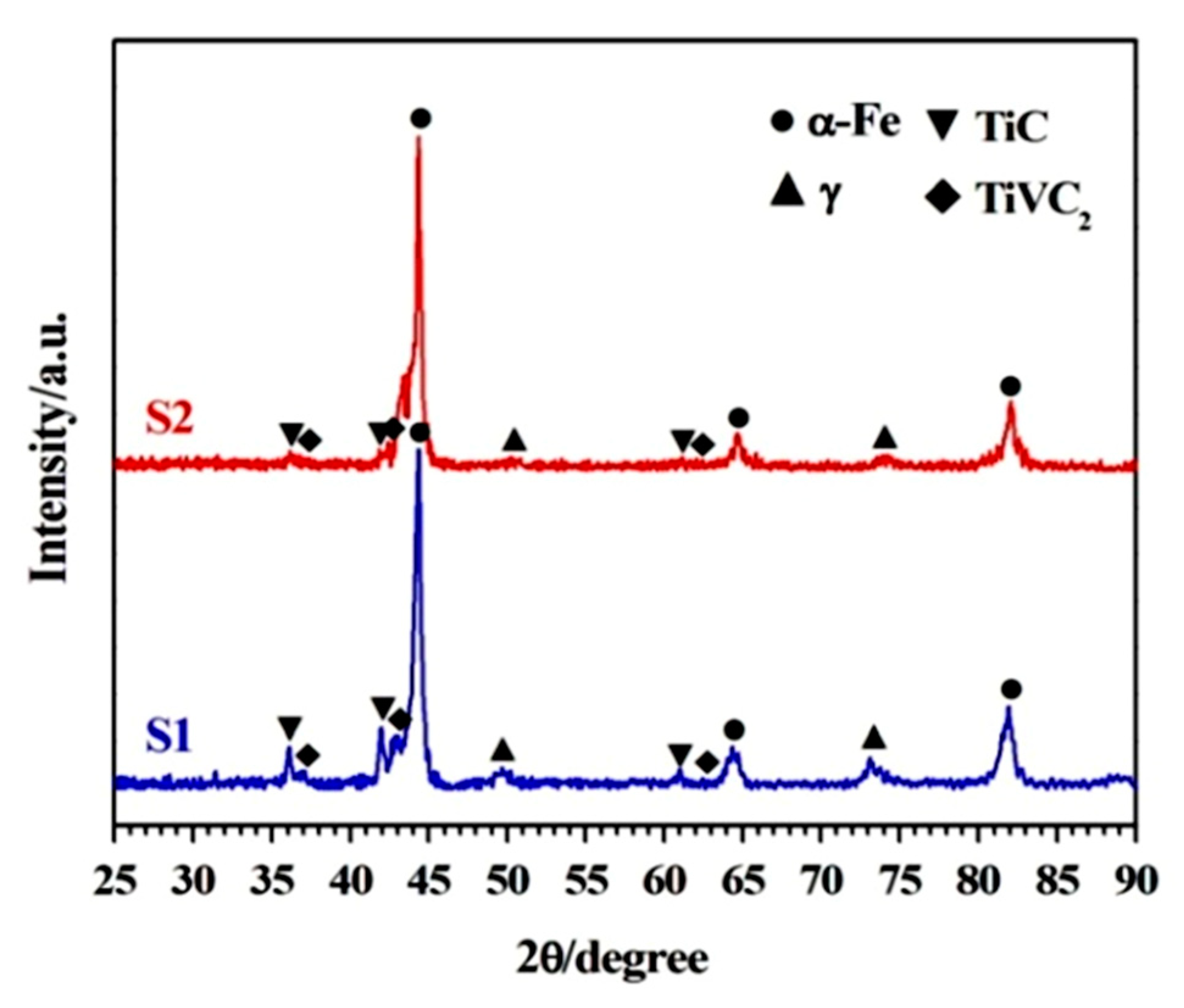
Figure 1. X-ray diffraction patterns of cladding layers.
Metals 10 00742 g001
Figure 2. Optical morphologies (a) S1 (b) S2 cladding layer and secondary electron micrographs (c) S1 (d,e) S2 cladding layer.
Metals 10 00742 g002
Figure 3. Average size of the layer matrix grains and carbides in the two cladding layers.
Metals 10 00742 g003
Figure 4. (a) Three-dimensional morphologies of wear scars in S1 and (b) S2 cladding layers (c) wear volume of the cladding layers.
Metals 10 00742 g004
Figure 5. (a) The average microhardness on the upper surface and (b) the friction coefficients of the cladding layers.
Metals 10 00742 g005
Figure 6. Secondary electron micrograph of wear morphologies (a,b) S1 and (ce) S2 cladding layer.
Metals 10 00742 g006
Table 1. Particle size of the cladding alloy powders.
SamplesIron PowderFerrotitanium-Ferrovanadium PowderGraphite Powder
S1 layer23–38 μm180–380 μm180–380 μm
S2 layer180–380 μm23–38 μm1.25–2.70 μm