Article

Numerical Analysis of Stress Distribution in Offshore Wind Turbine M72 Bolted Connections

Offshore Renewable Energy Engineering Centre, Cranfield University, Cranfield MK43 0AL, UK
*
Author to whom correspondence should be addressed.
Metals 2020, 10(5), 689; https://doi.org/10.3390/met10050689
Submission received: 3 May 2020 / Revised: 21 May 2020 / Accepted: 22 May 2020 / Published: 24 May 2020
(This article belongs to the Special Issue Microstructure, Deformation, and Fatigue Behavior in Metals)

Abstract

:
The use of bolted joints to connect the transition piece and monopile is nowadays widely applied in the offshore wind industry. Traditionally, grouted connections were used in the early generation of offshore wind turbines, but the experienced failures in such connections led to an increased tendency towards bolted flange connections to join the transition piece and monopile in the new generation of offshore wind turbines. The bolts used for this purpose have high strength and huge sizes, and are subjected to a preload that is applied during the tightening process. The present study is focused on the analysis of preload effects on stress distribution in M72 bolted connections by considering different friction coefficients between the bolt and nut threads. The bolt is considered to be made of grade 10.9 steel, whereas the nut is assumed to be made of grade 8.8 steel, which is a softer material. Using the finite element commercial software package Abaqus, numerical models were developed and analysed to establish trends for stress distribution and plastic strains during the bolt tightening process, and to quantify stress concentration factors in individual engaged threads.

1. Introduction

The connections between the offshore wind turbine (OWT) foundation and the transition piece (TP) are key mechanisms to enhance the stability and integrity of these offshore structures. Depending on the water depth and the distance from the shore, a number of different types of foundations are available to support the OWTs. This paper focuses on monopiles, which represent by far the highest percentage of the overall installed capacity of OWT support structures in Europe and have already proven their feasibility for different projects around the world. The transition piece and the monopile (MP) foundation must be safety attached together (often referred to as MP-TP connection) for the entire duration of the operational lifespan to ensure stability in the OWT structure. One of the main structural integrity challenges in the offshore wind industry is the presence of wind, wave, and current forces, which are constantly acting on the structure, with variable amplitude cyclic loads causing fatigue and corrosion damage in OWTs [1,2], particularly under adverse weather conditions such as thunderstorms and gales. Therefore, the connection between the foundation and the transition piece must be reliable and stable to resist such aggressive loading conditions. There are three main connection types that have been developed during the last decades for MP-TP connections: (a) grouted connections, (b) slip joint connections, and (c) bolted flange connections. A lot of hard work and comprehensive research has proven to be behind all of the mentioned design types, while the offshore wind industry has been continuously monitoring the performance and durability of each of these connection types in real-life structures.
In order to achieve a stable MP-TP connection, the initial solution adopted and widely used by the offshore industry was the grouted connection, mainly because it had already proven to be reliable and durable for oil and gas marine platforms [3]. As shown in Figure 1, this kind of connection is based on filling the space between two concentric tubular parts with different diameters (MP and TP) with a cementitious grout cast [4]. Thus, the load transfer method is imposed through shear friction mobilised by a normal stress induced through interlocking of surface imperfections and compression of the grout [4]. In 2008, some problems started to appear related to the use of these grouted connections in wind turbines located at the Princess Amalia wind farm [5] due to vertical settlements at the grouted joint between the MP and TP. This event led to significant repair, replacement, and financial loss of around €47 million. Similar slipping problems also appeared in the Kentish flats (UK) and Horns Rev I (Denmark) offshore wind farms [6].
In order to prevent such failures related to grouted connections, conical shaped grouted connections were designed to avoid settlement issues [7], and it was proven that the implementation of shear keys efficiently reduced damage in the grout [8]. These shear keys (see Figure 1) provide extra resistance against slipping and consist of circumferential welds on both TP and MP surfaces. In 2015, unexpected slippage problems at the MP-TP connections were observed and reported in some offshore wind farms. The investigations showed that the capacity for grouted connections to bear loads, established by the DNV J101 standard [9], turned out to be overestimated, which resulted in failures in grouted connections. Although the mistake in the standard was corrected later, this unfortunate event led to significant financial losses for the offshore wind operators.
Following numerous failures in MP-TP grouted connections, an effort was made to investigate possible alternative solutions, which led to the design of the single and double slip joint concepts (see Figure 1). In the double slip joint concept, two sets of rings with conical surfaces, which are made of steel, are introduced in the tubular monopile and transition piece, and the latter is lifted inside the monopile. The contact is made between two sets of rings, which have a small tapered angle, and bending moments are transferred by friction mechanisms [10]. On the other hand, the single slip joint concept is based on manufacturing the tower, transition piece, and monopile with conical shapes so that they can fit into each other and maintain stability through the friction between individual parts [11]. The slip joint concepts are still at the development and testing stage, but they are expected to provide promising solutions for the future generation of OWTs mainly due to the design simplicity and the reduced installation time [11].
The third MP-TP connection type, which has become increasingly popular in the offshore wind sector, particularly after the failures experienced in the grouted connections, is a bolted ring flange connection (see Figure 1). The ring flange connection is a well-established concept that has been employed for many years in onshore wind turbines [12,13,14]. This concept has been largely used in the development of recent offshore wind farm projects in Europe, such as the Humber Gateway Wind Farm (UK) and Amrumbank West (Germany) [15]. Ring flanges are manufactured on the inner surface of both MP and TP, with attachments made using large scale high-strength bolts (i.e., up to M72), which are protected against corrosion by a hot-dip galvanized treatment. It is worth noting that the bolt size in OWTs is generally much larger than those used in onshore wind turbines. Nowadays, bolted flange connections are considered one of the most promising solutions for the offshore wind industry, because they provide a safe and secure connection between the MP and TP.
The main issue related to the implementation of the bolted connections is the variation in preload, which must be kept within a pre-defined range to ensure structural stability [16]. Recommendations for a systematic calculation process are provided in the VDI 2230 standard [17], which are valid for steel bolts exposed to temperatures within the range −40 °C to 300 °C. The nominal preload level is often established by the DASt-Guideline 021 German standard [18] with an average preload value of around 70% of the material’s yield stress in individual bolts, while the maximum preload level must be kept below 90% of the yield stress [19]. An important challenge in the structural integrity assessment of bolted flange connections used in the offshore wind industry is the investigation of the likelihood of fatigue crack initiation and propagation at the engaged threads. Therefore, the current study is focussed on the engineering stress analysis of the bolt and nut connections during the preload process and identification of the load distribution across different engaged threads. Moreover, the formation of plastic deformation and high triaxiality regions in the engaged threads has been thoroughly investigated to develop a deep understanding of the life expectancy and inspection requirements for these bolted connections.

2. Materials and Methodology

In order to run the finite element simulations in Abaqus, the first step involved creating the bolt and nut geometries with material properties associated to grade 10.9 and 8.8 steel, respectively. In the next step, the created geometries were assembled and the boundary conditions were applied by fixing the nut and stretching the bolt. An interaction between both parts was also defined, with a friction coefficient of 0.3, appropriate for steel-to-steel contact when one of the components is hot-dip galvanized. To simulate the bolt tightening process, the preload was applied on the bolt using a pressure of 658 MPa, which corresponds to 70% of the yield stress, which is approximately 940 MPa for grade 10.9 steel bolts [19].
Two different models were initially created in finite element simulations: an axisymmetric model and a three-dimensional (3D) model. The purpose of running these two models in parallel was to compare and verify the results in order to apply the axisymmetric model, which saves computational time. In both models, a high resistance bolt of class M72 with 6 mm pitch size, made of grade 10.9 steel, was simulated. A total bolt length of 600 mm was considered, in accordance with ANSI/ASME B1.13M-1995 [20], and a symmetry boundary condition was applied to model half of the geometry. Moreover, a hexagon nut with a distance between two parallel sides of 105 mm and a height of 58 mm was modelled with grade 8.8 steel properties assigned to it. For simplicity, a circumferential thread geometry was considered in the bolt and nut without modelling the spiral pattern in the threaded connections. Further details about the model set-up, meshing strategy, and mesh convergence analysis are described below.

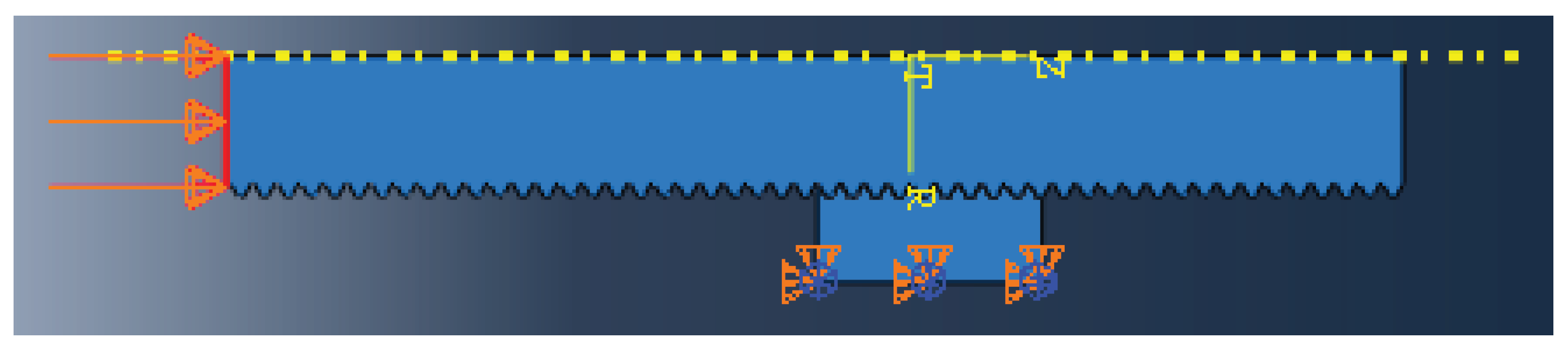
2.1. Axisymmetric and 3D Model Set-Up

An axisymmetric model was firstly created (see Figure 2) to develop a general understanding of the stress distribution in the threaded connections. This type of model was based on a revolved symmetry pattern around the central axis of the bolt and nut and was deemed useful due to the substantial saving in the computational time and power by the considerably smaller number of nodes and elements in the model. In addition to the axisymmetric model, a full 3D model was created using the same dimensions with the geometry shown in Figure 3. The same properties, boundary conditions, and meshing strategy were applied to both the axisymmetric and 3D models. Both models were analysed using elastic properties, and the same element size around the threaded connections was assigned to compare the agreement between the axisymmetric model and the 3D model. The results showed excellent agreement between the two models; hence, the rest of the simulations from this point onwards were conducted on the axisymmetric model, which requires a significantly lower number of elements and computational power compared to the 3D model.

2.2. Mesh Convergence Analysis

A mesh sensitivity analysis was carried out on the axisymmetric model, around the threaded connection between the nut and bolt, to identify the optimum element size for finite element simulations. As shown in Figure 4a, a “path” was defined along the root of the first engaged thread, which is the region of interest with the highest percentage of load distribution compared to other engaged threads. The path, depicted in red, was divided into 21 nodes to capture the stress distribution profile at the root of the thread. Linear elastic simulations were carried out using three-node axisymmetric elements (CAX3) assigned to the geometry, and the mesh refinement was continued until a convergence was observed in the predicted results. The mesh sensitivity analysis results are presented in Figure 4b. As seen in this figure, the predicted stress results at the root of the first engaged thread started to converge when Mesh 4 (with 105,673 number of elements) was assigned to the geometry. Therefore, from this point onwards, the element size in Mesh 4 was employed in the analysis of the stress distribution in the bolted connections. The variation in the number of elements and element size is shown in Figure 5, where Figure 5a demonstrates the coarse mesh (Mesh 1) and Figure 5b shows the fine mesh (Mesh 4) examined during the mesh sensitivity analysis.

2.3. Axisymmetric and Elastic–Plastic Model

The stress distribution analysis in the bolted connections was conducted using the elastic properties given in Table 1, and the results are shown in Figure 6. It can be seen in Figure 6 that the highest stress level was observed at the root of the first engaged thread. Further seen in this figure is that under the given loading condition, the stress levels predicted at the first three engaged threads exceeded the yield stress of the bolt material (which is approximately 940 MPa, as shown in Table 1), indicating that elastic–plastic simulations must be performed to obtain accurate predictions of the stress distribution around the root of the engaged threads.
In order to account for plasticity, the room temperature elastic–plastic properties shown in Table 1 and Figure 7 for the nut and bolt materials were implemented in finite element simulations. While the full tensile curve for the nut material (grade 8.8 steel) was available in the literature and directly employed in numerical simulations, only limited data points on the tensile properties of the bolt material (grade 10.9 steel) could be found in the open literature. Therefore, Hill’s material model was employed to generate the estimated tensile curve for the bolt material using a limited number of available data points [16]. An iterative process was performed in this approach to identify the optimum solutions of material constants for grade 10.9 steel based on the least squares method. According to Hill’s model, which is also known as the offset method, the strain ε can be correlated with the applied stress σ using:
ε = σ E + 0.002 ( σ σ y ) n
where E is the elastic Young’s modulus, σ y is the yield stress of the material, and n can be defined using the following equation:
1 n =   log σ UTS σ y / log   ε ( σ UTS ) ε ( σ y )
where σ UTS is the ultimate tensile strength, ε ( σ UTS ) is the strain corresponding to σ UTS , and ε ( σ y ) is the strain corresponding to σ y (which is often taken as 0.2% proof stress). The main elastic–plastic properties for the bolt [16] and the nut [21] materials are summarised in Table 1, and the tensile curves are demonstrated in Figure 7.

3. Stress Distribution Results in Bolted Connections

Once the plastic properties were identified for the bolt and nut materials, finite element simulations were repeated on the axisymmetric model using the elastic–plastic properties, and the results are presented in this section. It is worth noting that the mesh sensitivity analysis was repeated using the elastic–plastic properties, and the converged results were found to appear using Mesh 4, similar to that shown in Figure 4b. Moreover, the stress concentration factor (SCF) across different engaged threads, the influence of hardening layer formation due to the thread rolling process, as well as the friction coefficient effects on the stress distribution were investigated and discussed in this section.

3.1. Stress Concentration Factor

An important investigation that was carried out in this study is the systematic analysis of stress distribution in the engaged threads between the nut and bolt. This analysis was conducted under a preload equivalent to 70% of the bolt material’s yield stress, and the results are presented in terms of the SCF, which is the ratio of the local stress at the root of the thread to the nominal stress applied globally on the bolt. Analysing SCF is crucial in order to identify the most vulnerable regions in the bolted connections, where there is a higher likelihood of crack initiation and propagation. Previous studies on smaller bolts suggest that the highest values of SCF are expected to be observed along the first few engaged threads [22,23]. In the current study, the variations in SCF values were quantitatively analysed at the root of the threads in the bolt and also in the nut, as shown in red and blue lines, respectively, in Figure 8.
Two approaches were adopted to analyse the SCF distribution across the engaged threads:
(1)
Using the maximum von-Mises stress value at the root of the nut and bolt threads.
(2)
Using the average von-Mises stress value around the root of the nut and bolt threads.
The obtained results from numerical simulations are presented in Figure 9 and Figure 10 based on the maximum and average stress values at the root of the engaged threads, respectively. Moreover, the percentage of stress distribution at the bolt threads, calculated based on the maximum and average stress values, is demonstrated in Figure 11. It can be seen in Figure 9 that the first engaged thread exhibited the highest value of SCF, calculated based on the maximum stress at the root of the thread, with a gradual decrease in the values of SCF as the engaged thread number increased. This figure also shows that the value of SCF in the first five bolt threads was almost double those predicted in the nut threads. This was thought to be due to the higher yield stress and hence the greater load carrying capacity of the bolt material compared to the softer nut material.
The SCF variation calculated based on the average stress at the root of the engaged threads in Figure 10 shows that a similarly high SCF value was found at the first engaged bolt thread; however, the average stress values were considerably lower in the rest of the bolt threads. This indicates that among the first few engaged bolt threads, the first thread was at the highest risk of failure due to not only highest value of maximum stress but also a similarly high value of average stress around the root of the thread. Figure 10 also shows that, similar to the observations made in Figure 9, the nut threads had lower SCF values compared to the bolt threads, although the difference based on the average stress analysis in Figure 10 was not as large as the maximum stress values shown in Figure 9. It can be observed in Figure 11 that while the first bolt thread tolerated approximately 22% of the overall stress, based on the average stress at the root of the thread, the combination of SCFs in the first three engaged bolt threads accounted for approximately 50% of the total stress distribution across the total number of engaged threads (44% and 52% based on the maximum and average stress values, respectively). This implies that the risk of deformation and failure was the highest in the first three engaged bolt threads due to significantly higher stress levels that they tolerated compared to the rest of the threads. These results are in good agreement with the findings from other researchers [22,23].

3.2. Analysis of Triaxiality around the First Engaged Thread

As seen in Section 3.1., the highest stress level in the bolted connection was observed around the first engaged thread. Therefore, further analysis was performed to study the triaxiality in this region to identify the most critical region around the bolt thread, which is prone to fatigue crack initiation when the tightened bolt is subjected to cyclic loading condition. The variation in triaxiality, which is defined as the ratio of hydrostatic pressure (i.e., mean stress) to equivalent stress, is shown in Figure 12. Also included in this figure is the plastic strain distribution around the first engaged thread. It can be seen in Figure 12 that the highest plastic strain value was located close to the region of the highest triaxiality value. This figure shows that the top and bottom corners of the first engaged bolt thread and the neighbouring region at the bottom corner of the tooth of the nut exhibited the highest triaxiality and plastic strain values; hence, these are the critical locations that are vulnerable for crack initiation, and therefore need to be inspected in the M72 bolted connections during operation.

3.3. Rolling Effect on Strain Distribution

The bolts are initially manufactured by cutting threads and can be subsequently cold-rolled to enhance the mechanical and fatigue properties in the thread connections, which experience cyclic loading conditions during operation. The rolling process is carried out by placing the bolt between two threaded dies, which apply pressure, and cold-rolling the root of the threads by rotating the bolt. The bolt material is not removed during the rolling process but is displaced, which results in formation of a thin strain hardened layer at the root of the threads. It is known that cold-rolling using sufficiently high pressure will result in an increase in the hardness and yield stress. Moreover, the cold-rolling process induces a layer of compressive residual stress near the outer surface, which prolongs the fatigue life of the given metallic material [24]. A simple analysis was performed in this study to examine the effect of the cold-rolling process on the plastic strain distribution around the first engaged thread. This analysis was conducted by partitioning a thin layer (i.e., 0.5 mm) around the bolt threads and assigning elastic-perfectly plastic material properties, with the yield stress close to the σ UTS of the bolt material, to this thin layer in order to replicate the hardening effects on the mechanical properties in the near surface region of the threads. For simplicity, the compressive residual stresses were not modelled in the simulation, and only the strain hardening effects of the rolling process were taken into account.
In order to examine the influence of cold-rolling process on the plastic strain distribution around the first engaged thread, simulations were performed under the same loading condition (i.e., 70% of the yield stress of the bolt material) with and without the near surface hardened layer, and the results are shown in Figure 13. It can be seen in Figure 13 that under the given loading condition, the size of the plastic strain region around the first engaged thread was slightly reduced in the simulation with a hardened layer. This was thought to be due to a small percentage of difference between σ y and σ UTS of grade 10.9 steel, which are 940 and 1040 MPa, respectively (see Table 1). This implies that while the cold-rolling process can demonstrate a beneficial effect in plastic strain distribution in the threaded connections, the beneficial effect from this process will be more significant on materials that have a larger difference between σ y and σ UTS . Further studies need to be conducted in future work to examine the compressive residual stress effects on the stress/strain distribution and fatigue crack initiation behaviour of the threaded connections as a result of the cold-rolling process.

3.4. Influence of Lubricants on the Stress Distribution around the Threaded Connections

Another important analysis that was performed in this study was the investigation of the influence of friction coefficient between the nut and bolt contact regions on the stress distribution around the threaded connections. For this purpose, simulations were conducted with friction coefficient values of 0.05, 0.3, and 0.6, and the results were compared with each other. Some examples of the friction coefficient values for various lubricants, taken from the VDI 2230 standard for “Systematic Calculation of High Duty Bolted Joints” [17], are shown in Table 2.
Comparison of the results at the first engaged thread shown in Figure 14 reveals that as the friction coefficient value increased, the plastic strains were transferred from the top corner of the bolt thread to the bottom of the nut tooth. This resulted in an increase in the maximum plastic strain value in the nut, while the plastic strain in the bolt continuously decreased by increasing the friction coefficient. The results show that the use of lubricants (which reduce the friction coefficient) may concentrate the plastic strain in the root of the bolt thread, while the higher friction between the engaged threads increases the chances of deformation and failure in the tooth of the nut, rather than the bold thread. From an operation and maintenance (O&M) point of view, the deformation in the nut might be favourable as it is easier and cheaper to replace a nut rather than a bolt, although the nut is more difficult to inspect. It is important to note that in the current study, the nut was considered to be made of a softer material compared to the bolt, which can explain the reason for the formation of more significant plastic strains in the nut as a result of increases in the friction coefficient.
The variations in the maximum stress values at the root of the first three engaged nut and bolt threads are presented in Figure 15. This figure shows that the friction coefficient effect on the stress distribution in the nut and bolt threads was greater at the first engaged thread, while the results remained almost unchanged in the second and the third engaged threads. This indicates that the inspections during the operational life cycles of the M72 bolted connections in OWTs must be mainly focussed on the first engaged thread in the nut and bolt regardless of the type of lubricant used and the corresponding value of friction coefficient.

4. Discussion

The results obtained from the present study show that the preload applied during the tightening process is the direct cause of plastic strains formed around the nut and bolt threads. It is worth noting that the tightening load in this study was chosen as a proportion of the M72 bolt material’s yield stress; therefore, a wider range of high strength steels can be considered in future work to analyse their stress distribution at various preload levels. Additionally, it was demonstrated that the root of the first engaged thread in the bolt and the first tooth in the nut are the regions with higher plastic strains and triaxiality; therefore, these regions need to be inspected regularly to prevent and repair the crack initiation, particularly under fatigue loading conditions. In terms of the preload levels in OWT bolted connections, the external cyclic loads applied on the wind turbine structure can increase the local plasticity around the threaded connections above the levels predicted in the current study. Although the effect of external loads on the stress distribution in M72 bolted connections is beyond the scope of the present study, these cyclic loads need to be analysed and considered in future work to quantitatively identify their influence on the integrity assessment of threaded connections. Moreover, further tensile tests and sensitivity analysis need to be conducted as part of a future study to investigate the effect of experimental scatter in material properties on the stress distribution prediction results across the engaged threads in bolted connections.
It was also shown in this study that lubrication has an effect on the stress and strain distribution in the nut and bolt threaded connections, and an increase in the friction coefficient decreases the plastic strain in the bolt but on the contrary increases the plastic strain in the nut. This observation implies that in the absence of any lubricants, the nut, which is an easier component in the bolted connections to replace, is more prone to deformation and failure. This means that although lubricants are known to have a beneficial effect in bolted connections, the tightening of the M72 bolts and nuts without any lubricants may increase the operational life of the bolt while more attention must be paid to replacing the damaged nuts before their final failure subsequent to initial plastic deformation. It is worth noting that if a nut fails in OWT bolted connections, the preload on the corresponding bolt is lost and therefore more severe load levels are applied on the neighbouring bolts, which can result in damage and formation of cracks in other bolts. Finally, it was demonstrated that the SCF values are generally higher in the bolt threads compared to the nut, which can be attributed to the higher strength of the bolt material, which results in greater capacity of stress distribution in the bolt compared to the nut. Last but not least, although the results showed that the highest SCF is predicted to be observed at the first engaged thread, it is recommended to also inspect the second and the third engaged threads in the nut and bolt threaded connections to account for possible manufacturing imperfections, which cannot be modelled in finite element simulations.

5. Conclusions

High strength M72 bolts are widely used in MP-TP flange connections in OWTs. The results from this study show that almost half of the applied load during the tightening process is distributed across the first three engaged threads. The results also show that the highest plastic strain and triaxiality are observed at the top corner of the root of the first engaged bolt thread and the bottom corner of the first engaged tooth of the nut. Furthermore, it has been shown that the cold-rolling process can potentially reduce the plastic strain level and enhance the fatigue life of the bolt by inducing a thin layer of compressive residual stress at the root of the bolt thread. Finally, it has been shown that increasing the friction coefficient results in a lower stress in the first engaged bolt thread, while it increases the plastic deformation and stress level in the nut. Further analysis will be performed in future work to examine the influence of external cyclic loads on the stress distribution and structural integrity assessment of M72 bolted connections in OWTs.

Author Contributions

R.R.: methodology, investigation, writing; A.M.: conceptualization, supervision, writing—review and editing. All authors have read and agreed to the published version of the manuscript.

Funding

This work was supported by grant EP/L016303/1 for Cranfield, Oxford and Strathclyde Universities’ Centre for Doctoral Training in Renewable Energy Marine Structures - REMS (http://www.rems-cdt.ac.uk/) from the UK Engineering and Physical Sciences Research Council (EPSRC).

Acknowledgments

The authors would like to thank John Wintle, from TWI Ltd, for his constructive comments and guidance throughout this project.

Conflicts of Interest

The authors declare no conflict of interest.

References

  1. Mehmanparast, A.; Taylor, J.; Brennan, F.; Tavares, I. Experimental investigation of mechanical and fracture properties of offshore wind monopile weldments: SLIC interlaboratory test results. Fatigue Fract. Eng. Mater. Struct. 2018, 41, 2485–2501. [Google Scholar] [CrossRef]
  2. Mehmanparast, A.; Brennan, F.; Tavares, I. Fatigue crack growth rates for offshore wind monopile weldments in air and seawater: SLIC inter-laboratory test results. Mater. Des. 2017, 114, 494–504. [Google Scholar] [CrossRef] [Green Version]
  3. Gjersøe, N.F.; Hansen, N.-E.O.; Iversen, P. Long Term Behaviour of Lateral Dynamically Loaded Steel Grout Joints. In Proceedings of the The Twenty-first International Offshore and Polar Engineering Conference, Maui, HI, USA, 19–24 June 2011; International Society of Offshore and Polar Engineers: Maui, HI, USA, 2011; p. 7. [Google Scholar]
  4. Dallyn, P.; El-Hamalawi, A.; Palmeri, A.; Knight, R. Experimental testing of grouted connections for offshore substructures: A critical review. Structures 2015, 3, 90–108. [Google Scholar] [CrossRef] [Green Version]
  5. Lankhorst, S. ENECO: Update on the grouting issue of Princess Amalia Wind Farm. Available online: https://www.offshorewind.biz/2015/12/10/eneco-update-on-the-grouting-issue-of-princess-amalia-wind-farm (accessed on 21 May 2020).
  6. Tziavos, N. Experimental and Numerical Investigations on Grouted Connections for Monopile Offshore Wind Turbines. Ph.D. Thesis, University of Birmingham, Birmingham, UK, 2019. [Google Scholar]
  7. Lotsberg, I.; Serednicki, A.; Oerlemans, R.; Bertnes, H.; Lervik, A. Capacity of cylindrical shaped grouted connections with shear keys in off shore structures. Struct. Eng. 2013, 91, 42–48. [Google Scholar]
  8. Schaumann, P.; Lochte-Holtgreven, S.; Bechtel, A. Fatigue Design for Axially Loaded Grouted Connections of Offshore Wind Turbine Support Structures in Deeper Waters. In Earth and Space 2010: Engineering, Science, Construction, and Operations in Challenging Environments; American Society of Civil Engineers: Reston, VA, USA, 2010; pp. 2047–2054. [Google Scholar]
  9. The Supreme Court. MT Højgaard A/S (Respondent) v E. ON Climate & Renewables UK Robin Rigg East Limited and another (Appellants). Case ID: UKSC 2015/0115. August 2017. Available online: https://www.supremecourt.uk/cases/uksc-2015-0115.html (accessed on 21 May 2020).
  10. Van Gelder, B. Double Slip Joint—innovative foundation connection for offshore wind. In Proceedings of the WindEurope Conference, Hamburg, Germany, 27–29 September 2016. [Google Scholar]
  11. Grow, First Offshore Wind Turbine Using the Slip Joint Connection Successfully Installed. 2018. Available online: https://grow-offshorewind.nl/first-offshore-wind-turbine-using-the-slip-joint-connection-successfully-installed (accessed on 21 May 2020).
  12. Pavlović, M.; Heistermann, C.; Veljković, M.; Pak, D.; Feldmann, M.; Rebelo, C.; da Silva, L.S. Friction connection vs. ring flange connection in steel towers for wind converters. Eng. Struct. 2015, 98, 151–162. [Google Scholar] [CrossRef]
  13. Pavlović, M.; Heistermann, C.; Veljković, M.; Pak, D.; Feldmann, M.; Rebelo, C.; da Silva, L.S. Connections in towers for wind converters, part I: Evaluation of down-scaled experiments. J. Constr. Steel Res. 2015, 115, 445–457. [Google Scholar] [CrossRef]
  14. Pavlović, M.; Heistermann, C.; Veljković, M.; Pak, D.; Feldmann, M.; Rebelo, C.; da Silva, L.S. Connections in towers for wind converters, Part II: The friction connection behaviour. J. Constr. Steel Res. 2015, 115, 458–466. [Google Scholar] [CrossRef]
  15. Gollub, P.; Jensen, J.F.; Giese, D.; Güres, S. Flanged foundation connection of the offshore wind farm Amrumbank West-Concept, approval, design, tests and installation. Stahlbau 2014, 83, 522–528. [Google Scholar] [CrossRef]
  16. Braithwaite, J.; Mehmanparast, A. Analysis of tightening sequence effects on preload behaviour of offshore wind turbine M72 bolted connections. Energies 2019, 12, 4406. [Google Scholar] [CrossRef] [Green Version]
  17. Verein Deutscher Ingenieure. VDI 2230 Blatt-1. Systematic Calculation of High Duty Bolted Joints—Joints with One Cylindrical Bolt; Oak Ridge National Lab: Oak Ridge, TN, USA, 2003. [Google Scholar]
  18. DASt-Guideline 021: Schraubenverbindungen aus Feuerverzinkten Garnituren M39 Bis 72; Deutscher Ausschuss für Stahlbau DASt, Stahlbau Verlags- und Service GmbH: Düsseldorf, Germany, 2013. (In German)
  19. Nord-Lock Group. Comparison of Common Bolt Tightening Methods. Available online: https://www.nord-lock.com/insights/knowledge/2014/comparison-of-common-bolt-tightening-methods (accessed on 21 May 2020).
  20. Metric Screw Thread-M Profile. An American National Standard. ASME B1.13M. 1995. Available online: https://www.asme.org/codes-standards/find-codes-standards/b1-13m-metric-screw-threads-m-profile (accessed on 21 May 2020).
  21. Kontolati, K.; Panagouli, O. Numerical Investigation of Weak Axis i Profile Connections; University of Thessaly: Volos, Greece, 2017. [Google Scholar]
  22. Liu, J.; Ouyang, H.; Ma, L.; Zhang, C.; Zhu, M. Numerical and theoretical studies of bolted joints under harmonic shear displacement. Lat. Am. J. Solids Struct. 2015, 12, 115–132. [Google Scholar] [CrossRef] [Green Version]
  23. Zhao, H. Stress concentration factors within bolt-nut connectors under elasto-plastic deformation. Int. J. Fatigue 1998, 20, 651–659. [Google Scholar] [CrossRef]
  24. Unglaub, J.; Jahns, H.; Thiele, K. Finite Element Analysis of Residual Stresses in Large Cold-Rolled Threads. In Proceedings of the XV International Conference on Computational Plasticity: fundamentals and applications (COMPLAS 2019), Barcelona, Spain, 3–5 September 2019. [Google Scholar]
Figure 1. Monopile to transition piece (MP-TP) connection types.
Metals 10 00689 g001
Figure 2. Axisymmetric model of the bolted connection.
Metals 10 00689 g002
Figure 3. Three-dimensional model of the bolted connection.
Metals 10 00689 g003
Figure 4. (a) The defined path along the root of the first engaged thread; (b) mesh sensitivity analysis results.
Metals 10 00689 g004
Figure 5. Demonstration of the (a) coarse mesh and (b) fine mesh examined during the mesh sensitivity analysis.
Metals 10 00689 g005
Figure 6. Stress distribution analysis using elastic properties.
Metals 10 00689 g006
Figure 7. Stress–strain curves for grade 10.9 and 8.8 steels.
Metals 10 00689 g007
Figure 8. Stress concentration factor (SCF) analysis at the root of the threads in the bolt (red lines) and the nut (blue lines).
Metals 10 00689 g008
Figure 9. Stress concentration factor across the root of the bolt threads based on the maximum stress values.
Metals 10 00689 g009
Figure 10. Stress concentration factor across the root of the bolt threads based on the average stress values.
Metals 10 00689 g010
Figure 11. Percentage of stress distribution in the bolt threads.
Metals 10 00689 g011
Figure 12. (a) Plastic strain and (b) triaxiality distribution around the first engaged thread.
Metals 10 00689 g012
Figure 13. Plastic zone size in the simulations (a) without and (b) with a near surface hardened layer.
Metals 10 00689 g013
Figure 14. Maximum plastic strain in elastic–plastic simulations with the friction coefficient values of (a) 0.05, (b) 0.3, and (c) 0.6.
Metals 10 00689 g014
Figure 15. Variations in the maximum stress values at the root of the engaged threads (a) in the nut and (b) in the bolt as a result of change in the friction coefficient.
Metals 10 00689 g015
Table 1. Elastic–plastic properties for the bolt and nut materials.
Material Type σ y   ( MPa ) σ U T S   ( MPa ) ε   ( σ U T S ) E (GPa)
Nut (8.8 steel)6408000.022210
Bolt (10.9 steel)94010400.095210
Table 2. Friction coefficient values for different lubricants, data from [17].
Friction CoefficientMaterialLubricant
0.04–0.01Black oxide coating, zinc laminated coating, electroplated coating, metallically brightSolid lubricants, liquefied wax, wax dispersions
0.20–0.35Austenitic steel, electroplated coatings, hot dip galvanizedOil for the austenitic and none for the rest
>0.3Electroplated coatings, austenitic steel and Al, Mg alloysNone

