Abstract
A TA1 (Ti alloy)/low alloy steel (LAS) composite plate was manufactured by explosive welding. The effects of the bonding interface microstructure on the mechanical properties and fracture behavior of the composite plate were investigated. The results show that the interface has a wavy structure with intermetallic compounds (IMCs) enclosed by a steel matrix. The metallurgical bonding interface was achieved by local diffusion, with a several micrometer-thick diffusion layer. Two kinds of microcracks were formed in the IMC region and the diffusion interface. Microcracks in the IMC region propagate with difficulty due to the impediment of the IMC/steel interface. The microcracks initiated at the interface need to propagate into the fine-grain steel matrix before crack connection and delamination. The shear strength of the TA1/LAS composite plate was over 350 MPa. The composite plate could be bent up to the equipment limit (135 degrees). Excellent mechanical properties were obtained since the crack propagation was hindered by the refined or elongated steel grains induced during explosive welding.
1. Introduction
Titanium alloys are used widely in aviation, aerospace, nuclear power generation, and marine and petrochemical engineering for their light weight, excellent mechanical properties at room and elevated temperatures, and good corrosion resistance [1,2]. However, Ti alloys are too expensive to produce thick devices. Structural steels are low-cost and can offer high strength to composite plates. Therefore, in combination with the functional properties of Ti alloys and the low cost of structural steels, the production cost of composite plates can be minimized, which is advantageous for promoting the wide application of the composite plate.
The production of a composite plate with Ti alloys and steels requires a reliable bonding interface between these dissimilar alloys. Different welding techniques have been used to produce Ti/steel composite plates [3,4,5,6,7,8]. For example, Balasubramanian produced Ti/steel joints by diffusion welding. He found that various intermetallic compounds (IMCs) formed in the diffusion zone, weakening the mechanical properties of the Ti/steel joints [3]. Chen et al. produced Ti/steel joints with laser butt welding and found that the fractures are brittle for various IMCs formed along the interface [4]. Yu et al. prepared Ti/steel composite plates with hot-roll bonding, determining that the interface is ductile when the formation of IMCs is inhibited [6]. Miriyev et al. used a spark plasma sintering technique to join Ti to steel, and found that a titanium carbide layer formed at the bonding interface could prevent the formation of IMCs [8]. These results suggested that the preparation of high-quality Ti alloy/steel composite plates is very difficult, mainly due to brittle IMCs that are always formed at the bonding interface through atom diffusion. Miriyev et al. suggested that IMCs significantly reduce the mechanical properties of the composite plate [8,9,10]. Moreover, Ti and steel exhibit significant differences in their chemical and physical properties, and titanium alloy easily absorbs nitrogen and oxygen, making it difficult to avoid bonding defects [11,12]. These problems make conventional welding unsuitable for producing Ti/steel composite plates.
Explosive welding is a widely used technique in the manufacture of composite plates [13,14]. It is well known that explosive welding can directly weld similar metals [15,16] and dissimilar metals [14,17,18,19] that are not easily welded by other techniques. The composite plates prepared by explosive welding usually have a wavy metallurgical interface [14,16,19,20,21,22]. The wavy bonding interface is caused by the pressure impulses when the plates collide [23,24,25]. Moreover, the metallurgical bonding interface does not cause significant crystallization or phase transformation. As such, Bataev et al. showed that explosively welded plates can have higher mechanical properties than bulk plates with similar chemical compositions [26]. Therefore, explosive welding has been used since its invention to design and control the microstructure of the interfaces of dissimilar materials and enforce their mechanical properties [13].
Explosive welding is very suitable for the control of the microstructures of Ti/steel interfaces to improve interfacial strength and offers a great potential for the high-quality welding of Ti and steel. So far, many scholars have researched the interface structure of Ti/steel explosive-welded composite plates. Nishida et al. found metastable phases produced at the bonding interfaces of the Ti/steel joints to be inevitable during the melting of the bonding interface [27]. Xie et al. also found brittle Fe diffusion zones, formed near the bonding interface of CP-Ti/X65 composite plates, produced by explosive welding and hot rolling [20]. Song et al. found that four successive hierarchical structures are formed at the interface of the explosively welded Ti/steel cladding joint. Metastable Fe9.64Ti0.36 and FeTi are formed near the crest region, and these inclusions are always accompanied by similar dimension microcracks [28]. Yang et al. found that very fine grains are produced in the adiabatic shear band in the Ti/steel explosive-welded bonding interface, which suggests a recrystallization process took place during the explosion [29]. Kahraman et al. found that brittle IMCs lead to a decrease in the mechanical properties of Ti/steel joints, and the reduction of brittle IMCs is a key step for improving the mechanical properties [30]. The relationship between the interface structure produced by explosive welding and its influence on the mechanical properties and crack propagation in Ti/steel composite plates has not been studied.
However, there are limited studies on the effect of microstructure on the crack propagation and its effect on the mechanical properties of explosively welded Ti/steel composite plates. The objective of this work is to analyze the effect of bonding interface microstructure on the mechanical properties and crack propagation of dissimilar Ti/steel composite plates. The results of this work are useful for the design of bonding microstructures to obtain excellent mechanical properties in explosively welded Ti/steel composite plates.
IMCs are a key factor in controlling the mechanical properties of the Fe/Ti interface. In addition, the ductile phase has an important influence on the performance of the weld. Chu et al. found that crack nucleation and propagation in Ti/Fe composite plates were affected by the structures of the IMC and ductile phases [31]. Therefore, it is worth investigating the effect of the complex bonding interface produced by explosive welding on the mechanical properties and crack propagation of dissimilar Ti/steel composite plates.
In this paper, TA1 and low alloy steel (LAS) composite plates were produced by explosive welding. Their microstructure was analyzed using optical microscopy (OM), scanning electron microscopy (SEM) and energy spectrum analysis (EDS). Furthermore, their mechanical properties were studied using microhardness, tensile, shear and bend testing.
2. Materials and Methods
A schematic illustration of the explosive welding is shown in Figure 1. The flyer and base plates were made of TA1 and low carbon steel, respectively. The sizes of TA1 and LAS used are 1020 mm × 1020 mm × 2 mm and 1000 mm × 1000 mm × 16 mm, respectively. In the present work, the composite plate was explosively welded by using expanded ammonium nitrate as an explosive material. The thickness of the explosive is 30 mm, and the density is 0.6 g/cm3. The stand-off distance is 6mm, and detonation velocity was 2.1 km/s. The compositions of the TA1 and LAS are given in Table 1 and Table 2, respectively.
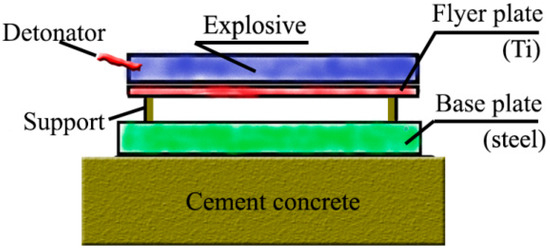
Figure 1.
Schematic illustration of the process of explosive welding.

Table 1.
The chemical composition (wt%) of the TA1.

Table 2.
The chemical composition (wt%) of the LAS.
The microstructure of the composite plate was observed by OM (LEICA DMIRM, Leica, Beijing, China)and SEM (Helios Nanolab600i, FEI Hillsboro, OR, USA) equipped with EDS. Hardness measurements were done using an HVS-1000A tester (Huayin, Laizhou, China), with a 50 g and 25 g load on steel and Ti alloy, respectively. Samples were etched with a mixture of 3.5% HNO3 and 96.5% C2H5OH, and a Keller reagent for LAS and Ti alloy, respectively. Shear tests and bend tests were performed with an INSTRON 5565 universal testing machine (Instron, Shanghai, China). Shear testing was performed in the compression direction according to GB/T6396-2008 (similar to JISG0601-2002). A schematic illustration of the shear test apparatus is shown in Figure 2. The shearing area was fixed as 25 mm × 3 mm, and the compression speed was 1mm/min. The shear stress, , is given by:
where and e are the width and height of the test interface, respectively.
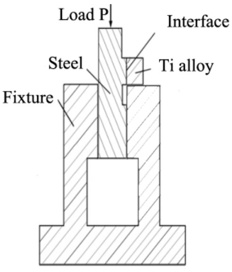
Figure 2.
Schematic illustration of shear test apparatus.
The effect of the microstructure of the bonding interface on the mechanical properties and crack propagation of the TA1/LAS composite plate was analyzed by a three-point bending test. The sample size in the bending test was 2 mm × 2 mm × 20 mm (the TA1 and LAS are both about 1 mm thick). The bend tests were performed using an AGX-plus machine (Shimadzu, Tokyo, Japan) at a leading speed of 1 mm/min.
3. Results and Discussion
An overview of a typical bonding interface region of the TA1/LAS composite plate obtained by optical microscopy is shown in Figure 3a. The metallographic studies show that there is no apparent IMC layer or macrocrack between TA1 and LAS, indicating that the bonding interface of composite plate was welded successfully. It is clear that the TA1/LAS interface has a wavy morphology with a period of about 1 mm and an amplitude of about 300 μm. Some vortices are formed in the crest of the wave. The wavy interface has a larger interface area than the straight interface, which is beneficial to the mechanical properties. The formation of waves is attributed to the high temperature and high pressure softening both the steel and Ti during the explosive welding process. The formation of the vortex structure is attributed to severe plastic deformation that leads to a localized plastic instability [32]. The microstructure of a typical crest of the TA1/LAS composite plate is shown in Figure 3b. The vortices are composed of IMCs and steel with equiaxed grains. The steel grains near the bonding interface are elongated during the explosive welding process. The thickness of the elongated grain region can reach up to 70 μm, which appears near the vortex. Figure 3c shows a typical interface microstructure near the trough region. Obviously, the thickness of the elongated grain region decreased with removal of the vortex, and the minimum thickness is only 20 μm. However, there is no obvious change in the Ti grains, which implies that the explosive welding has little effect on the Ti matrix.
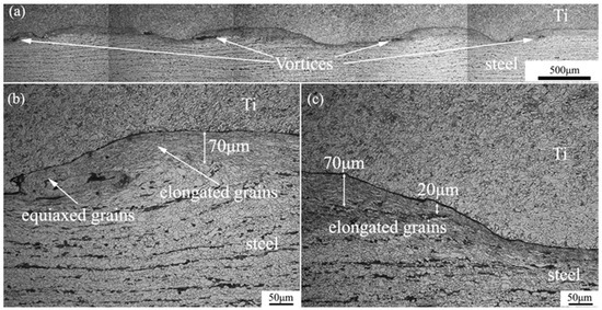
Figure 3.
Optical images of the interface in the TA1/LAS composite plate: (a) an overview image, (b) magnified image of the typical wave crest microstructure, (c) magnified image of the typical wave trough microstructure.
SEM micrographs of the detailed interfacial microstructure of the TA1/LAS composite plates are shown in Figure 4. It is evident that the equiaxed grains composing the vortex are about 2 μm as shown in Figure 4a. The microstructure of the TA1/LAS interface away from the vortex is shown in Figure 4b. The equiaxed grains also appear on the steel-rich side of the TA1/LAS interface, which is limited to a region of about 5 μm from the interface. Moreover, an elongated grain region was formed adjacent to the equiaxed grain region. These equiaxed grains were produced by dynamic recrystallization; therefore, the thickness of equiaxed grain regions in the wave crest region is larger than that of the wave trough region, due to the temperature in the wave crest region. These results reveal that the high friction of steel and Ti induces a large amount of plastic deformation in the matrix, which results in significantly refined/elongated grains in the steel plates.
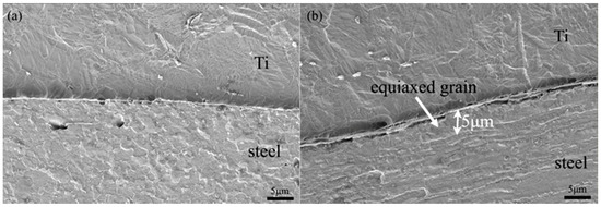
Figure 4.
SEM images of the detailed interfacial microstructure in an explosively welded TA1/LAS bimetallic sheet: (a) magnified image of the typical microstructure near the vortex, (b) magnified image of the typical microstructure away from the vortex.
A mapping scanning analysis for Ti and Fe contents was performed to investigate the components of the vortex structure. As shown in Figure 5, a typical vortex structure was composed of Ti, steel and IMCs enclosed by steel. Some microcracks appear in the IMC region due to rapid solidification and further cooling of the dissimilar matrixes. However, these microcracks only appear in the IMC region. This result indicates that the interfaces have the ability to absorb energy and suppress the microcracks from propagating further, contributing to the better plasticity of the fine grain steel around IMCs. Similar phenomena were also found in steel/steel [15] and Ti/Al explosively welded composite plates [33].
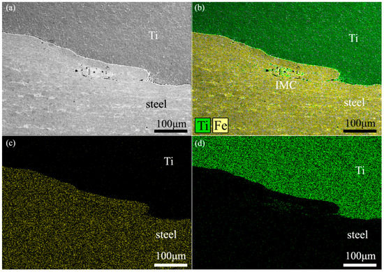
Figure 5.
(a) Bonding interface in TA1/LAS composite plate and (b) EDX analysis maps showing the distribution of Fe and Ti. EDX-derived elemental maps for (c) Fe and (d) Ti.
Elemental line scans of Fe and Ti using EDS were conducted to determine the distribution of elements across the bonding interface. Typical interface microstructure and compositional profiles of the Ti/steel interface without vortices in different regions are shown in Figure 6. It is evident that EDS did not show any traces of IMCs in the Ti/steel interface free of vortices. A thin diffusion layer appeared in the bonding interface. In the diffusion layer, the Ti concentration decreases from the TA1 side to the LAS side, while the Fe concentration gradient is the opposite. The high temperature and high pressure generated by the collision of the explosion welding are instantaneous (about 10−6 s) [13], so there is not enough time to form a thick diffusion layer and IMCs. The thickness of the diffusion layer is about 3 μm and 1 μm at the crest of the wave and the trough of the wave, respectively. The diffusion thickness in the wave trough region is much thinner than that at the crest of the wave. This is also caused by the crest of the wave due to the higher temperature during explosive welding.
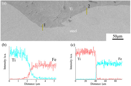
Figure 6.
(a) Typical interface microstructure of TA1/LAS composite plate and compositional profiles of Ti/steel interface in different regions from EDS: (b) at the trough of the wave (position 1), (c) at the crest of the wave (position 2).
The Vickers hardness profile across the bonding interface of TA1/LAS after explosive welding is shown in Figure 7. It can be seen that the maximum hardness of LAS was obtained near the bonding interface, then hardness values of LAS decrease with the increase in the distance form bonding interface until the distance reaches 500 μm, and then the hardness remained nearly constant. These results suggest the LAS near the bonding interface has the highest hardness. This is due to: (i) the fine grain strengthening effect caused by the formation of fine grains and elongated grains near the bonding interface during the explosion welding process and (ii) dislocation strengthening due to high dislocation density near the bonding interface. On the other hand, in the TA1 matrix, the hardness apparently does not change with distance from the bonding interface.
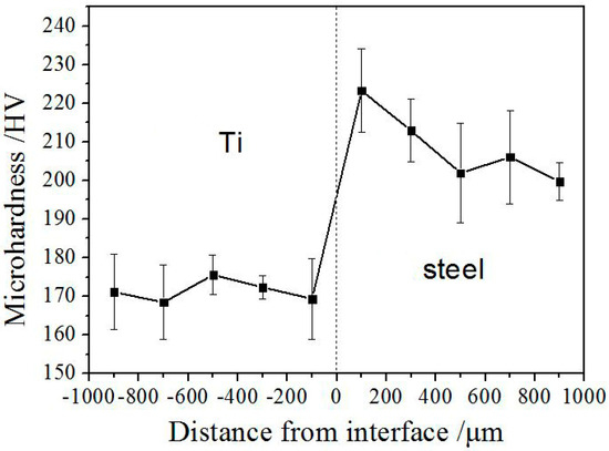
Figure 7.
Microhardness profile across the TA1/LAS bonding interface after explosive welding.
A shear strength test was conducted to check the bond strength of the TA1/LAS composite plate. A shear strength of over 350 MPa was achieved as shown in Figure 8. The shear strength was higher than those for explosive bonding between TA1 and 16Mn steel (about 250 MPa) [34], hot rolling bonding between TA2 Ti and Q235 steel with a DT4 steel interlayer (238 MPa) [6], diffusion bonding between CP Ti and 304 stainless steel with a copper interlayer (218 MPa) [35], and that for Ti alloy and AISI 304 stainless steel with a silver interlayer (149 MPa) [3].
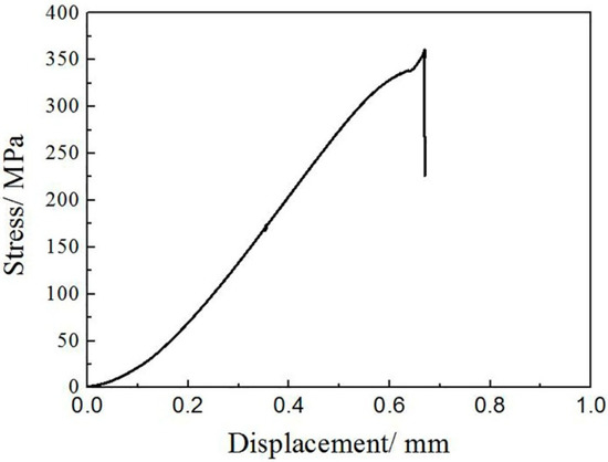
Figure 8.
Typical shear stress displacement curve of TA1/LAS composite plate achieved from shear tests.
Figure 9 shows the morphologies and mapping scanning analysis of the shear fracture of the TA1/LAS/ explosive welding composite plate. It is worth noting that some steel matrix appears on the fracture surface, which implies that cracks need to propagate into the steel matrix. Since the steel near the bonding interface is mainly composed of refined and elongated grains, the strength and plasticity of these grains are improved by fine grain strengthening; therefore, these steel grains can significantly improve the mechanical properties of the composite plate.
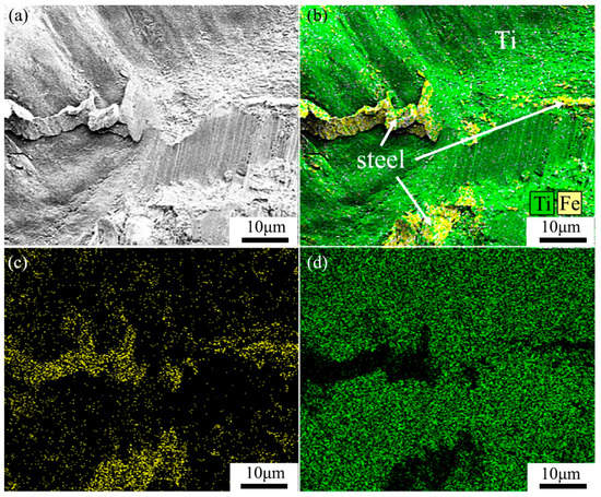
Figure 9.
(a) Morphologies of the shear fractures of LAS/TA1 and (b) EDX analysis maps showing the distribution of Fe and Ti. EDX-derived elemental maps for (c) Fe and (d) Ti.
In order to analyze the delamination resistance of the bonding interface, bending properties of the TA1/LAS composite plate were investigated. A macrograph of the bent TA1/LAS composite plate is shown in Figure 10. The specimens were neither separated nor cracked after bending to the equipment’s limit (135 degrees), indicating that an acceptable joining between TA1 and LAS was obtained by explosive welding.
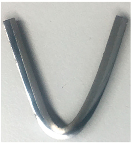
Figure 10.
Macrograph of explosively welded TA1/LAS composite plate after bending up to the equipment’s limit (135 degrees).
Bending tests were also used to analyze the effect of the bonding interface structure on the initiation and propagation of early microcracks. Figure 11a shows an SEM-BSE (Electron back scattered diffraction) picture of the interface after bending 30 degrees. It is evident that two kinds of microcrack appear in the BSE picture. One kind of microcrack occurred in the IMC region of the vortex as indicated by a red arrow. Another kind of microcrack occurred at the bonding interface of the crest of the wave as indicated by a green arrow, where there is a diffusion layer of about 3 μm. However, no microcracks appear at diffusion layers in wave trough regions, which suggests that the thinner diffusion layer could restrain the initiation of microcracks. The microcrack within the IMC region ended at the bonding interface between the IMC and the steel matrix. The result suggests that it is easy to generate microcracks in the IMC region, but microcrack propagation is hindered at the IMC/steel interface. As most IMC regions are enclosed by steel as shown in Figure 5, microcracks cannot propagate further. These results show that the IMC region is very susceptible to induce microcrack initiation; however, microcrack propagation will be hindered by the bonding interface, restraining further propagation and delamination. Figure 11b,c show the detailed micrograph of region A in Figure 11a before and after bending in order to analyze the process of microcrack propagation at the bonding interface. It is clear that there are some microcracks in the crest of the wave before bending as shown in Figure 11b, which are caused by the Ti/steel stress mismatch during the explosion welding process. Microcracks at the bonding interface are significantly propagated after bending as shown in Figure 11c, which suggests that the microcracks appearing at the diffusion interface are easier to propagate than microcracks in IMCs, and play a more important role in the delamination process.
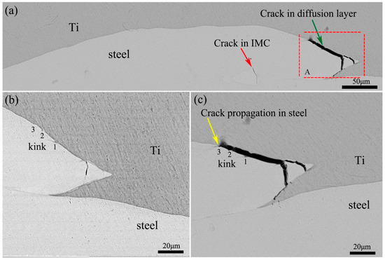
Figure 11.
SEM (BSE) micrographs of the specimen after three-point bending test (a) and detailed micrographs before (b) and after (c) bending test.
Fracture theory proposes that loading method and material inhomogeneity have significant effects on the microcrack propagation path. It is seen that there is some large angle bending at the bonding interface, which is indicated by kinks (at positions 1, 2 and 3). Similar interface structures were also found in other Ti/steel explosive-welded composites [31,34]. Because the diffusion layer is very thin, these interface kinks caused the steel matrix to appear in front of microcrack tips and promoted crack blunting, plastic energy dissipation before the microcrack tips, and propagation to the steel matrix as indicated by the yellow arrow. Therefore, the steel matrix was torn and fractures appeared as shown in Figure 9. The complex interface structure formed by explosive welding will inevitably affect the microcrack propagation path.
The damage modes of the welding interface always include crack initiation, crack growth, crack connection and delamination [33]. In diffusion-weld composite plates, the brittle IMC layer always contains FeTi and Fe2Ti, formed in the Ti/steel interface. This IMC layer exists as a thin plate that is always detrimental to the mechanical properties of the composite plate. The IMCs formed in the vortex region in explosive-welded composite plates may induce the initiation of microcracks under loading. However, these IMC regions are always enclosed by steel regions, which can stop the microcracks from propagating and delaminating. As a result, the diffusion layer at the interface of the Ti/steel composite during explosive welding plays a dominant role during the crack propagation process. The diffusion layer far from the crest of the wave is very thin and it is difficult for microcracks to be initiated or propagated at diffusion layers in wave trough regions, so the microcracks initiated in crest regions need to propagate over a long distance to connect. On the other hand, the microcrack always needs to propagate into the steel matrix to produce a kink in the layer structure, which obviously hinders microcrack propagation. These reasons make delamination more difficult, contributing to the improvement of the mechanical properties of the TA1/LAS composite plate.
4. Conclusions
In this work, the interface microstructure, mechanical properties and microcrack propagation of an explosive-welded TA1/LAS composite were investigated. The following conclusions can be drawn from this study:
- (1)
- A composite plate of TA1 alloy/LAS was accomplished by explosive welding. The shear strength of the bonding interface was over 350 MPa. The composite plate could be bent up to the equipment’s limit (135 degrees).
- (2)
- The bonding interface had a wavy appearance with periods of about 1 mm and amplitudes of about 300 μm. Some vortices were formed as well as IMC regions, which were enclosed by the steel matrix.
- (3)
- The metallurgical bonding interface was achieved by a local diffusion process during explosive welding. There were no IMCs in the Ti alloy/LAS bonding interface. The diffusion layers of bonding interface at the crest and trough positions were about 3 μm and 1 μm, respectively.
- (4)
- Grains near the interface were found to be refined or elongated due to recrystallization or plastic deformation during explosion. The hardness of steel near the interface was higher than that of the base materials due to deformation hardening.
- (5)
- Two kinds of microcracks were formed in the bending test. Microcracks initiated in IMC regions are difficult to propagate due to the hindering by the interface of IMC/steel. The microcracks initiated at the interface need to propagate into the fine grain steel matrix before crack connection and delamination. The complex interface structure produced by explosive welding hindered microcrack propagation, which improved the mechanical properties of the TA1/LAS composite plate.
Author Contributions
Performance of experiments, Y.C., D.L. and M.F.; analysis of experimental data, Y.C., D.C. and L.S.; explosive welding, G.D.; paper writing and editing, Y.C., Y.Z. and Z.Z. All authors have read and agreed to the published version of the manuscript.
Funding
This work was supported by the National Natural Science Foundation of China (Grant No. 51701051), NSFHLJ (JC2017012) and the Youth Talent Project of China National Nuclear Corporation (CNNC2019YTEP-HEU01).
Conflicts of Interest
The authors declare no conflict of interest.
References
- He, G.; Eckert, J.; Loser, W.; Schultz, L. Novel Ti-base nanostructure-dendrite composite with enhanced plasticity. Nat. Mater. 2003, 2, 33–37. [Google Scholar] [CrossRef]
- Ezugwu, E.O.; Bonney, J.; Yamane, Y. An overview of the machinability of aeroengine alloys. J. Mater. Process. Tech. 2003, 134, 233–253. [Google Scholar] [CrossRef]
- Balasubramanian, M. Application of Box-Behnken design for fabrication of titanium alloy and 304 stainless steel joints with silver interlayer by diffusion bonding. Mater. Des. 2015, 77, 161–169. [Google Scholar] [CrossRef]
- Chen, S.; Zhang, M.; Huang, J.; Cui, C.; Zhang, H.; Zhao, X. Microstructures and mechanical property of laser butt welding of titanium alloy to stainless steel. Mater. Des. 2014, 53, 504–511. [Google Scholar] [CrossRef]
- Deng, Y.; Sheng, G.; Xu, C. Evaluation of the microstructure and mechanical properties of diffusion bonded joints of titanium to stainless steel with a pure silver interlayer. Mater. Des. 2013, 46, 84–87. [Google Scholar] [CrossRef]
- Yu, C.; Xiao, H.; Yu, H.; Qi, Z.C.; Xu, C. Mechanical properties and interfacial structure of hot-roll bonding TA2/Q235B plate using DT4 interlayer. Mater. Sci. Eng. A 2017, 695, 120–125. [Google Scholar] [CrossRef]
- Ning, J.; Zhang, L.; Jiang, G.; Xie, M.; Yin, X.; Zhang, J. Narrow gap multi-pass laser butt welding of explosion welded CP-Ti/Q23513 bimetallic sheet by using a copper interlayer. J. Alloy Compd. 2017, 701, 587–602. [Google Scholar] [CrossRef]
- Miriyev, A.; Stern, A.; Tuval, E.; Kalabukhov, S.; Hooper, Z.; Frage, N. Titanium to steel joining by spark plasma sintering (SPS) technology. J. Mater. Process. Tech. 2013, 213, 161–166. [Google Scholar] [CrossRef]
- Qiu, R.F.; Iwamoto, C.; Satonaka, S. Interfacial microstructure and strength of steel/aluminum alloy joints welded by resistance spot welding with cover plate. J. Mater. Process. Tech. 2009, 209, 4186–4193. [Google Scholar] [CrossRef]
- Fronczek, D.M.; Wojewoda-Budka, J.; Chulist, R.; Sypien, A.; Korneva, A.; Szulc, Z.; Schell, N.; Zieba, P. Structural properties of Ti/Al clads manufactured by explosive welding and annealing. Mater. Des. 2016, 91, 80–89. [Google Scholar] [CrossRef]
- Sun, Z.; Annergren, I.; Pan, D.; Mai, T.A. Effect of laser surface remelting on the corrosion behavior of commercially pure titanium sheet. Mater. Sci. Eng. A 2003, 345, 293–300. [Google Scholar] [CrossRef]
- Chu, Q.; Bai, R.; Zhang, M.; Li, J.; Lei, Z.; Hu, N.; Bell, J.M.; Yan, C. Microstructure and mechanical properties of titanium/steel bimetallic joints. Mater. Charact. 2017, 132, 330–337. [Google Scholar] [CrossRef]
- Bataev, I.A.; Lazurenko, D.V.; Tanaka, S.; Hokamoto, K.; Bataev, A.A.; Guo, Y.; Jorge, A.M., Jr. High cooling rates and metastable phases at the interfaces of explosively welded materials. Acta. Mater. 2017, 135, 277–289. [Google Scholar] [CrossRef]
- Findik, F. Recent developments in explosive welding. Mater. Des. 2011, 32, 1081–1093. [Google Scholar] [CrossRef]
- Borchers, C.; Lenz, M.; Deutges, M.; Klein, H.; Gartner, F.; Hammerschmidt, M.; Kreye, H. Microstructure and mechanical properties of medium-carbon steel bonded on low-carbon steel by explosive welding. Mater. Des. 2016, 89, 369–376. [Google Scholar] [CrossRef]
- Zhang, L.; Pei, Q.; Zhang, J.; Bi, Z.; Li, P. Study on the microstructure and mechanical properties of explosive welded 2205/X65 bimetallic sheet. Mater. Des. 2014, 64, 462–476. [Google Scholar] [CrossRef]
- Paul, H.; Miszczyk, M.M.; Chulist, R.; Prazmowski, M.; Morgiel, J.; Galka, A.; Faryna, M.; Brisset, F. Microstructure and phase constitution in the bonding zone of explosively welded tantalum and stainless steel sheets. Mater. Des. 2018, 153, 177–189. [Google Scholar] [CrossRef]
- Fronczek, D.M.; Chulist, R.; Litynska Dobrzynska, L.; Kac, S.; Schell, N.; Kania, Z.; Szulc, Z.; Wojewoda-Budka, J. Microstructure and kinetics of intermetallic phase growth of three-layered A1050/AZ31/A1050 clads prepared by explosive welding combined with subsequent annealing. Mater. Des. 2017, 130, 120–130. [Google Scholar] [CrossRef]
- Zhang, N.; Wang, W.; Cao, X.; Wu, J. The effect of annealing on the interface microstructure and mechanical characteristics of AZ31B/AA6061 composite plates fabricated by explosive welding. Mater. Des. 2015, 65, 1100–1109. [Google Scholar] [CrossRef]
- Xie, M.X.; Zhang, L.J.; Zhang, G.F.; Zhang, J.X.; Bi, Z.Y.; Li, P.C. Microstructure and mechanical properties of CP-Ti/X65 bimetallic sheets fabricated by explosive welding and hot rolling. Mater. Des. 2015, 87, 181–197. [Google Scholar] [CrossRef]
- Yan, Y.B.; Zhang, Z.W.; Shen, W.; Wang, J.H.; Zhang, L.K.; Chin, B.A. Microstructure and properties of magnesium AZ31B-aluminum 7075 explosively welded composite plate. Mater. Sci. Eng. A 2010, 527, 2241–2245. [Google Scholar] [CrossRef]
- Gulenc, B. Investigation of interface properties and weldability of aluminum and copper plates by explosive welding method. Mater. Des. 2008, 29, 275–278. [Google Scholar] [CrossRef]
- Wronka, B. Testing of explosive welding and welded joints: Joint mechanism and properties of explosive welded joints. J. Mater. Sci. 2010, 45, 4078–4083. [Google Scholar] [CrossRef]
- Wronka, B. Testing of explosive welding and welded joints. The microstructure of explosive welded joints and their mechanical properties. J. Mater. Sci. 2010, 45, 3465–3469. [Google Scholar] [CrossRef]
- Wronka, B. Testing of explosive welding and welded joints. Wavy character of the process and joint quality. Int. J. Impact Eng. 2011, 38, 309–313. [Google Scholar] [CrossRef]
- Bataev, I.A.; Bataev, A.; Mali, V.I.; Esikov, M.A.; Bataev, V.A. Peculiarities of Weld Seams and Adjacent Zones Structures Formed in Process of Explosive Welding of Sheet Steel Plates. Mater. Sci. Forum 2011, 673, 95–100. [Google Scholar] [CrossRef]
- Nishida, M.; Chiba, A.; Honda, Y.; Hirazumi, J.I.; Horikiri, K. Electron microscopy studies of bonding interface in explosively welded Ti/steel clads. ISIJ Int. 1995, 35, 217–219. [Google Scholar] [CrossRef]
- Song, J.; Kostka, A.; Veehmayer, M.; Raabe, D. Hierarchical microstructure of explosive joints: Example of titanium to steel cladding. Mater. Sci. Eng. A 2011, 528, 2641–2647. [Google Scholar] [CrossRef]
- Yang, Y.; Wang, B.F.; Xiong, J.; Yang, X.Y.; Zeng, Y.; Chen, Z.P. Adiabatic shear bands on the titanium side in the titanium/mild steel explosive cladding interface: Experiments, numerical simulation, and microstructure evolution. Metall. Mater. Trans. A 2006, 37A, 3131–3137. [Google Scholar] [CrossRef]
- Kahraman, N.; Gulenc, B.; Findik, F. Joining of titanium/stainless steel by explosive welding and effect on interface. J. Mater. Process. Tech. 2005, 169, 127–133. [Google Scholar] [CrossRef]
- Chu, Q.; Zhang, M.; Li, J.; Yan, C. Experimental and numerical investigation of microstructure and mechanical behavior of titanium/steel interfaces prepared by explosive welding. Mater. Sci. Eng. A 2017, 689, 323–331. [Google Scholar] [CrossRef]
- Mousavi, S.A.A.A.; Sartangi, P.F. Experimental investigation of explosive welding of cp-titanium/AISI 304 stainless steel. Mater. Des. 2009, 30, 459–468. [Google Scholar] [CrossRef]
- Qin, L.; Wang, J.; Wu, Q.; Guo, X.Z.; Tao, J. In-situ observation of crack initiation and propagation in Ti/Al composite laminates during tensile test. J. Alloys Compd. 2017, 712, 69–75. [Google Scholar] [CrossRef]
- Ning, J.; Zhang, L.J.; Xie, M.X.; Yang, H.X.; Yin, X.Q.; Zhang, J.X. Microstructure and property inhomogeneity investigations of bonded Zr/Ti/steel trimetallic sheet fabricated by explosive welding. J. Alloy Compd. 2017, 698, 835–851. [Google Scholar] [CrossRef]
- Kundu, S.; Chatterjee, S. Microstructure and mechanical properties of diffusion bonded joints between titanium and stainless steel with copper interlayer. Sci. Technol. Weld. Joining 2007, 12, 572–578. [Google Scholar] [CrossRef]
© 2020 by the authors. Licensee MDPI, Basel, Switzerland. This article is an open access article distributed under the terms and conditions of the Creative Commons Attribution (CC BY) license (http://creativecommons.org/licenses/by/4.0/).