Article

Effect of TiO2-Nanoparticles on Ni Electrodeposition on Copper Wire

1
LPCMA, University of Biskra, B.P. 145, Biskra 07000, Algeria
2
LMSM, University of Biskra, B.P. 145, Biskra 07000, Algeria
3
CNRS, Institut de chimie moléculaire et des matériaux d’Orsay, Université Paris-Saclay, 91405 Orsay, France
*
Author to whom correspondence should be addressed.
Metals 2020, 10(3), 406; https://doi.org/10.3390/met10030406
Submission received: 13 January 2020 / Revised: 16 March 2020 / Accepted: 16 March 2020 / Published: 22 March 2020

Abstract

:
The objective of this work is to study, on a copper wire, the effect of TiO2-nanoparticles on electrodeposited nickel. Both the microstructure and surface morphology (texture) of the coating were investigated. This deposit is obtained from baths of sulfated electroplating Watts. The Ni-TO2 composite coating is deposited at a temperature of 45 °C. The composite deposit is prepared by adding nanoparticles of TiO2 to the electrolyte. The characterization has been carried out by X-ray diffraction, scanning electron microscopy, microhardness measurements, and electron backscatter diffraction (EBSD). Vickers microhardness was used to characterize the mechanical properties of the electrodeposited nickel. The results showed the effects of the TiO2 on the composition, the surface morphology, and the hardness of the deposited layer. However, there was not an effect of TiO2 nanoparticles on texture.

1. Introduction

The electrolysis is generally used to deposit one or more metal layers on a metallic surface. The principle of making an electrolytic deposit is simple: the part to be covered is placed in an electrolysis tank to act as a cathode on which metal ions are deposited. Electro-deposition of nickel is widely used, in particular, to improve surface properties like corrosion resistance, heat resistance and physical appearance. However, nickel-plated surface shows low surface mechanical properties such as hardness and wear resistance. To improve these properties electro-co-deposition of Ni with non-metallic particles is regularly investigated [1,2,3,4,5,6,7,8,9,10,11,12] and regarding the required characteristics of the nickel deposit an electroplating bath is selected. The most popular baths, among industrial methods of electrodeposition of nickel are Watts-type solutions. This type of bath was invented about 100 years ago by O.P. Watts [13]. For that main reason, Watt bath is used and is the most popular nickel electro plating bath. This bath is a combination of nickel sulfate and nickel chloride, along with boric acid. Boric acid is an essential ingredient for controlling the bath pH and forming smooth and ductile deposits [14]. The kinetics of nickel electrodeposition from the Watts bath is carried out by one adsorption and two electrochemical reactions, as mentioned by Cui et al. [15].
To improve the quality of nickel deposits, i.e., their physical and mechanical properties, various Ni-based composite coatings have been prepared by electrolytic deposition technique [16], and Ni-based binary composite coatings like Ni–Mo [16,17], Ni-Al2O3 [18], Ni-SiC [19], Ni-W [20], Ni-Cu [21], Ni-Sn [22], and Ni-TiO2 [23] were tried to serve as hydrogen electrodes [24]. As a consequence, electrodeposited Ni–TiO2 composites are largely used for their high corrosion resistance [24].
Electrodeposited Ni-TiO2 was investigated under different operating conditions, such as bath composition, pH, plating current density temperature, and plating time to find the optimum conditions for producing sound and satisfactory deposits. For example, Spanou et al. [25] studied the effect of nano-TiO2 particles added into a nickel electrolyte. They found at constant pH, the grain size increases with the increase of the current density. Stirring speed is one of the important parameters that control the mechanism of particle incorporation. Nanoparticles easily agglomerate when they are added in the plating bath. Consequently, fabrication of nanocomposite coatings requires higher stirring speeds [26]. Temperature also plays a significant role in co-deposition process. Increase in temperature enhances reaction kinetics, leading to more nickel ions to be transferred to the cathode. However, it has been reported that it is difficult to achieve a favorable incorporation of TiO2 nanoparticles due to their high surface energy, and although agitation and surfactants can diminish the agglomeration of these particles, their effects are limited [27].
A crystallographic aspect of the electrodeposited Ni-TiO2 remains a research question. The most previous research works are based on using XRD as a technique for studying the crystallographic aspect of these coatings [28,29]. For example, Yilmaz et al. [28] found that the presence of TiO2 in Ni coating influences the evaluation of the texture. X-ray diffraction (XRD) showed that under direct current conditions, the composite coating exhibited clearly [211] fiber orientation, while pulse current working exhibited a mixed crystal orientation through [100] and [211] axes. Benea and Danaila [29] studied by XRD the TiO2 nanoparticles electro–codeposition with nickel. By adding TiO2 nanoparticles into nickel Watts bath, the preferred orientation along (111) planes of Ni matrix did not change, and the intensity of this peak increases with increasing of TiO2 nanoparticles concentration in the plating bath. Spanou et al. [25] investigated by DRX of nanocomposite coatings, obtained by electrochemical codeposition of TiO2 nanoparticles with nickel, from an additive-free Watts type bath. It has been observed that the presence of TiO2 nanoparticles favors the [100] texture of nickel matrix. With increasing amounts of TiO2 nanoparticles in the bath, the incorporation of TiO2 nanoparticles into nickel matrix was found to modify significantly the texture of the deposits compared to pure Ni coatings under the same pH and applied current density values. Specifically, confinement of the [211] and [110] preferred orientation domains was observed followed by the predominance of [100] texture over an extended region of electrodeposition conditions. Additionally, a transformation of [210] preferred orientation to random oriented crystallites is observed in the presence of TiO2 nanoparticles.
However, according to the literature, the electron backscatter diffraction (EBSD) technique was applied just for studying the texture of Ni films processed by electrodeposition [30,31]. In their investigation, Kolonits et al. [30] found that during the heat treatment up to 750 K, a mixed (111) and (100) fiber texture was developed. Amblard and Froment [31] confirmed the development of fiber texture in thick Ni electrodeposits. Consequently, little works have been conducted by using EBSD technique.
In this paper, the effect of the Ni/TiO2 nanoparticles electrodeposited composite on a copper wire was studied. Two concentrations of TiO2 particles (5 and 10 g/L) were used in the electrolytic Watts bath. The investigation of both surface morphology and texture of the deposited layer was the main objective of this study. The novelty of this paper is in the texture investigation, because there is not a published investigation related to the study of Ni-TiO2 coatings by EBSD technique.

2. Materials and Methods

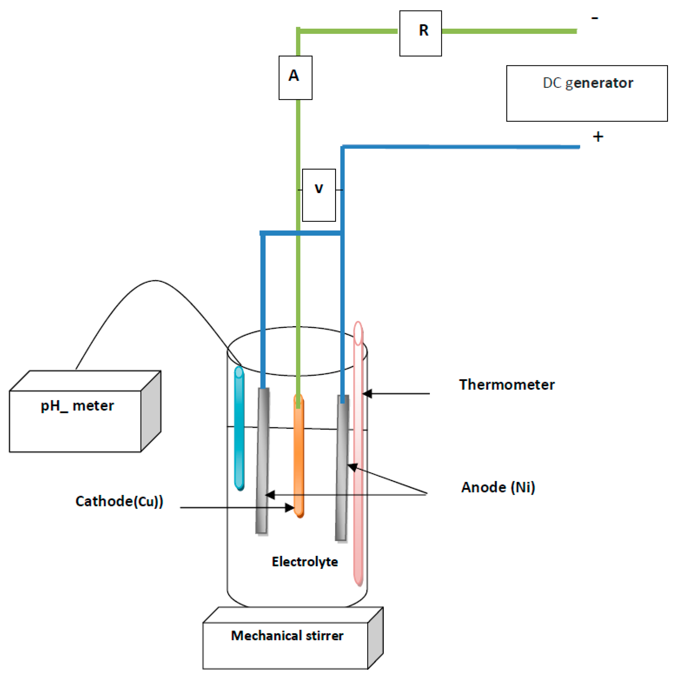
2.1. Electrodeposition of Ni–TiO2 Coatings

Figure 1 shows the schematic representation of the setup used for the electrodeposition. The main elements are: DC generator, pH–meter, mechanical stirrer with magnetic bar, and thermometer.
In this experiment, Ni–TiO2 coatings were electrodeposited on copper substrates from an electrolyte containing nickel chloride (NiCl2-6H2O: 0.5 mol/L), sodium chloride (NaCl: 0.1 mol/L), ammonium chloride (NH4Cl: 0.1 mol/L), and boric acid (H3BO3: 0.1 mol/L). Bid stilled water was used for electrolyte preparation. The pH of the solution was adjusted by addition of aqueous HCl or NaOH solutions. The pH of the final solution is 4, the current density used is 4 A/dm2 and the deposition time is approximately 25 min. Cathode copper wire (99.9%) is used as substrate with dimensions of 20 mm length and 2 mm diameter. It is an industrial pure copper, used in the manufacture of electrical wires. A nickel sheet (99.99 commercial purity) with dimension of 20 mm × 10 mm × 2 mm is used as anode. Before the electroplating process, the substrate was mechanically polished to surface finish using a succession of emery papers and then first cleaned in acetone. Then, it was washed in distilled water, activated in aqueous solution of 10% H2SO4 for 20 s, and washed again in distilled water before immersed in the plating bath for electrodeposition.
The TiO2 powder was purchased and used as received. This powder consists of a mixture of the crystalline phases of anatase and rutile [25]. The average particle size of the TiO2 nanoparticles powder used in the experiment was 23 ± 2 nm. The Ni-TiO2 coatings were deposited at different percentage of TiO2, namely: 5 and 10 g/L. TiO2 particles were maintained as a suspension in an electrolytic bath by continuous magnetic stirring at a rotating speed of 500 rpm for at least 26 h before deposition.

2.2. Morphological and Structural Characterization

A scanning electron microscope (SEM-model VEGA3, Advance Scientific Equipment Pvt. Ltd., Mumbai, India) operated at 30 kV and equipped with an energy dispersive X-ray spectrometer (EDS-Bruker X Flesh Detector 610M, Billerica, MA, USA) was used for imaging and chemical composition microanalysis on sample cross section. X-ray diffraction analyses were carried out on longitudinal direction of coated wire by using a Siemens D5000 diffractometer, with Cu Kα radiation (λ = 1.54056 Å) to determine the main phases and the texture of the deposits. The scan rate was 0.04° per sec over a 2Ө ranging from 20° to 90°. Microhardness tester (M-400-A hardness tester, LECO, St. Joseph, MI, USA) using 200 gf was used to measure the surface hardness of the electrodeposited nickel.

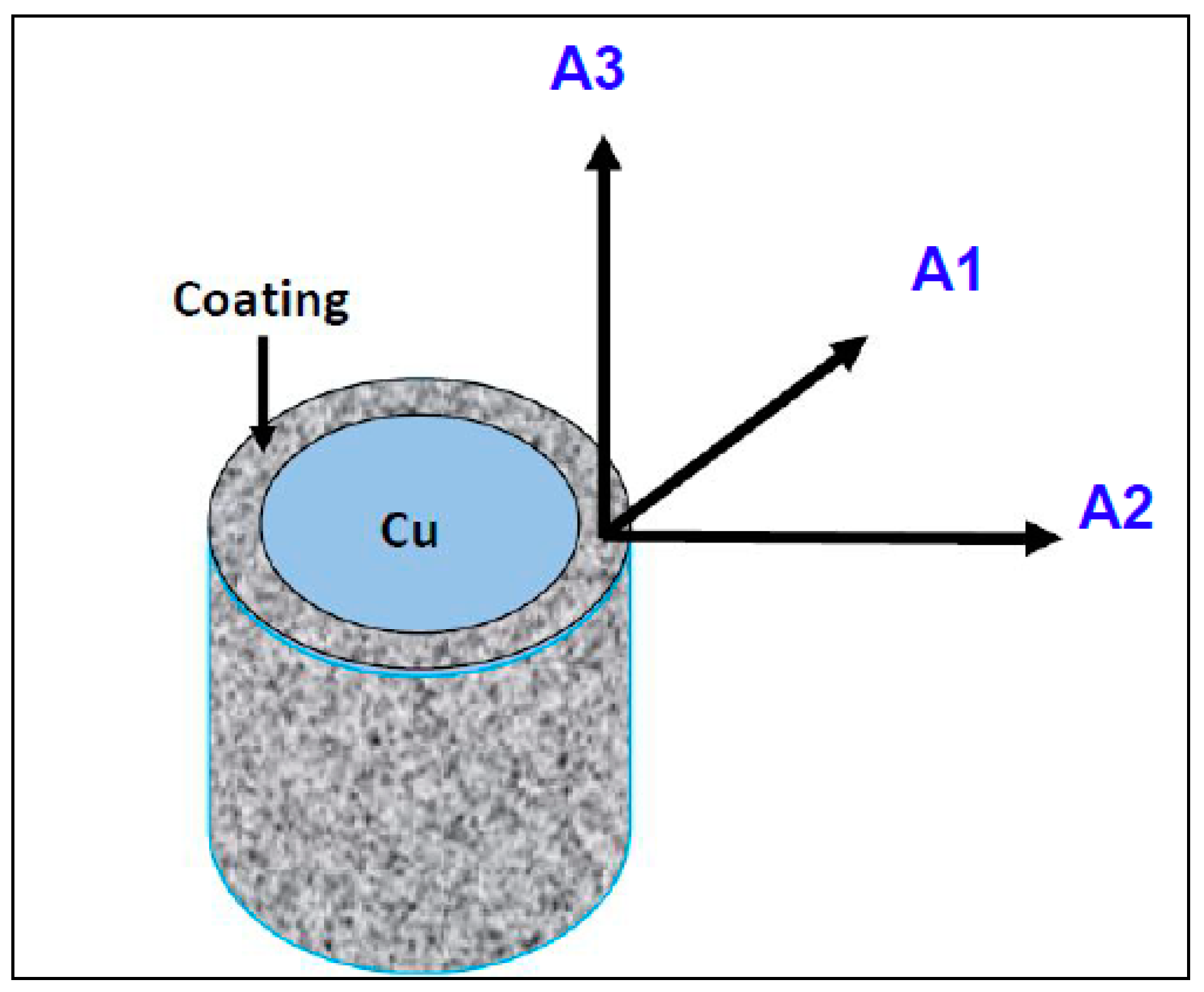
2.3. Electron Backscatter Diffraction (EBSD) Technique

The purpose of the EBSD experiments was to determine whether or not any significant texture is resulted from the coating process. Specimens were prepared for EBSD analysis in a standard manner. A Zeiss Sigma HD FEG-SEM(Carl Zeiss Microscopy GmbH, Jena, Germany) operating at 20 kV coupled with the automatic OIMTM (Orientation Imaging Microscopy) software from TSL-EDAX Company (Mahwah, NJ, USA) was used for the sample cross section EBSD analyses. Figure 2 presents the schematic illustration of the studied area. The pole figures were calculated, using the harmonic series expansion method (series rank L = 22), from the orientations measured by EBSD. Let us remark that it was verified that higher L values do not modify significantly the texture intensity. Each orientation was modeled by a Gaussian function with a 5° half width. The EBSD maps are measured in the (A1, A2) plane, at the interface between the Cu substrate and the coating (Figure 2).

3. Results

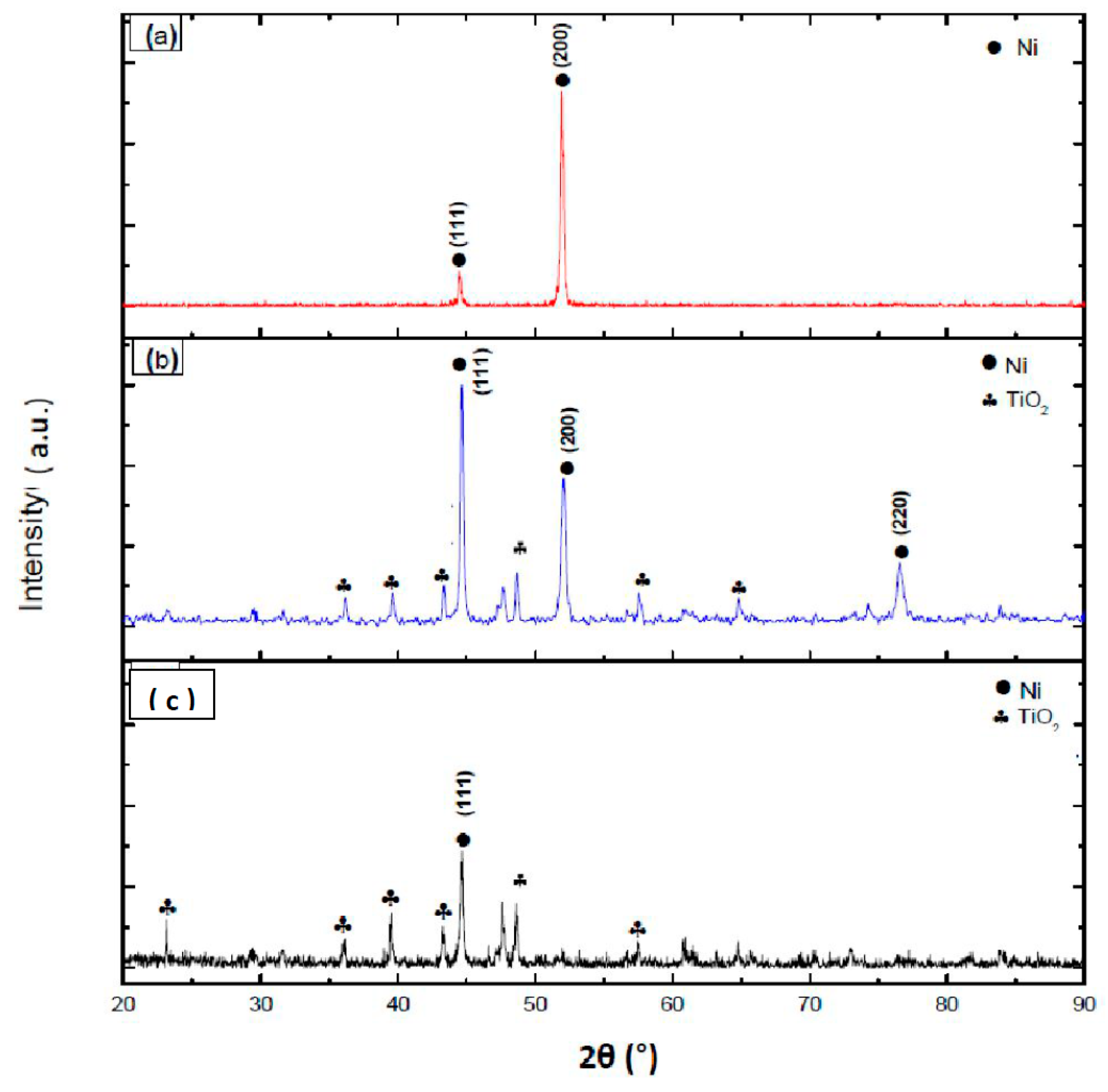
3.1. X-ray Diffraction Technique

X-ray diffraction patterns of the electrodeposited Ni on copper with and without the addition of TiO2 nanoparticles are presented in Figure 3. First of all, the X-ray diffraction patterns of the Ni layer, without addition of TiO2, shows the two main peaks of the (111) and (200) plane families and no peaks characteristic of any other phase were recorded. The (200) peak has a higher intensity than the (111) peak which indicates a preferred orientation (texture) of the Ni due to selective grain growth.
However, with the presence of TiO2 nanoparticles in the nickel-plating bath, TiO2-peaks were recorded (Figure 3b,c). The incorporation of 5 g/L of TiO2 in the nickel-plating bath shows a preferential orientation of the Ni crystals, as the Ni (200) diffraction peak decreases, while the (111) peak increases in intensity (Figure 3b). The TiO2 peaks were revealed at low angles which is in agreement with the result of Benea and Danaila [29].

3.2. SEM Observations

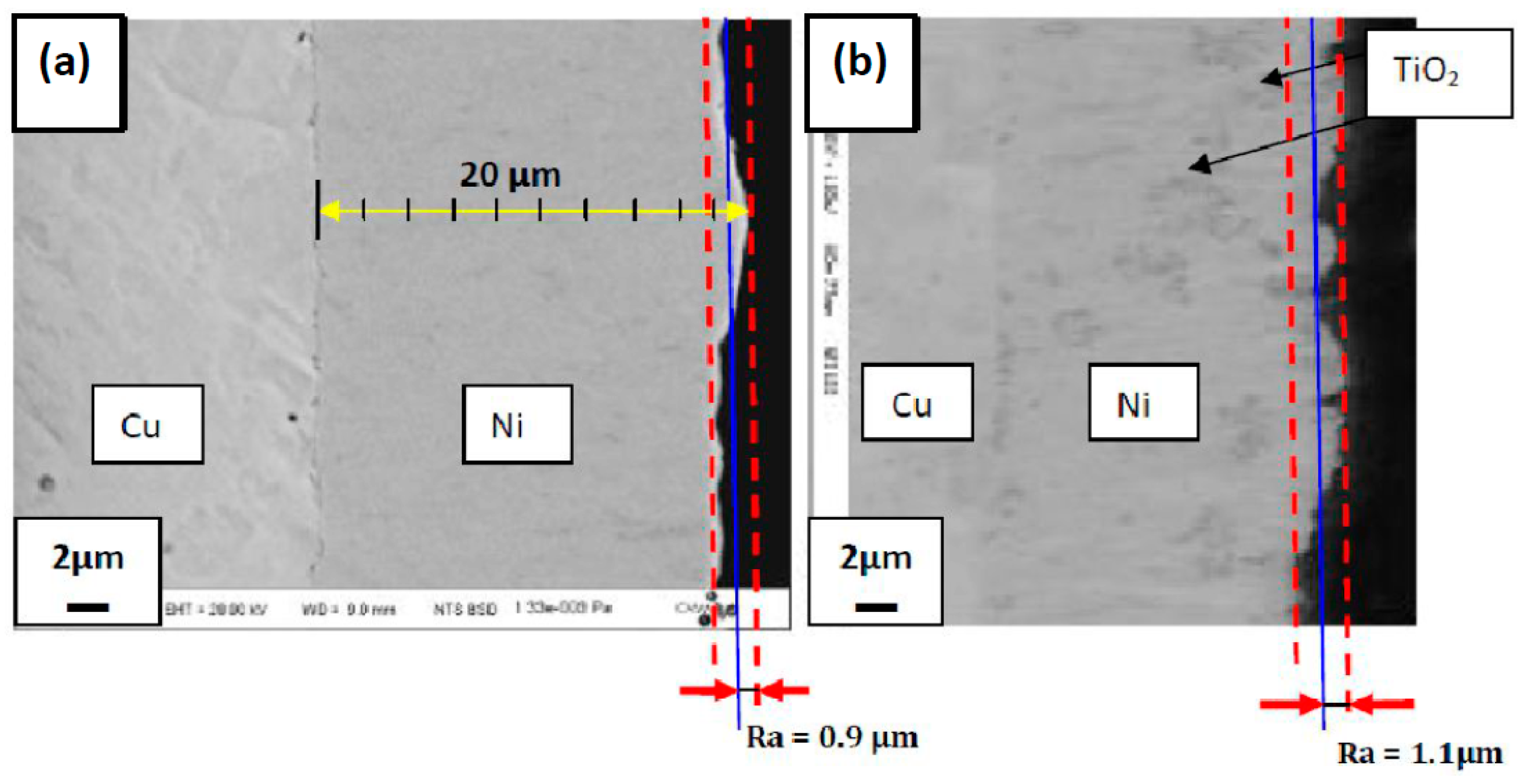
3.2.1. Cross Section Observation

Figure 4 presents typical SEM images of the electrodeposited Ni on the copper wire with and without the addition of TiO2. From these SEM observation (Figure 4a), the average thickness of the deposited layer is between 18 and 20 μm. These microstructures did not reveal any defect, but the effect of TiO2 nanoparticles on the coated copper is well highlighted on Figure 4b, because some regions appear darker than the rest of the coating. These regions correspond to agglomerations of the TiO2 during the electrodeposition process. The agglomerated TiO2 appear more located at the top of the deposited (Figure 4b).
In addition, the surface roughness Ra is measured by applying the reported work [32]. Microroughness is formed by fluctuations in the surface. From Figure 4a,b, the value of Ra varies from 0.9 to 1.1 μm.

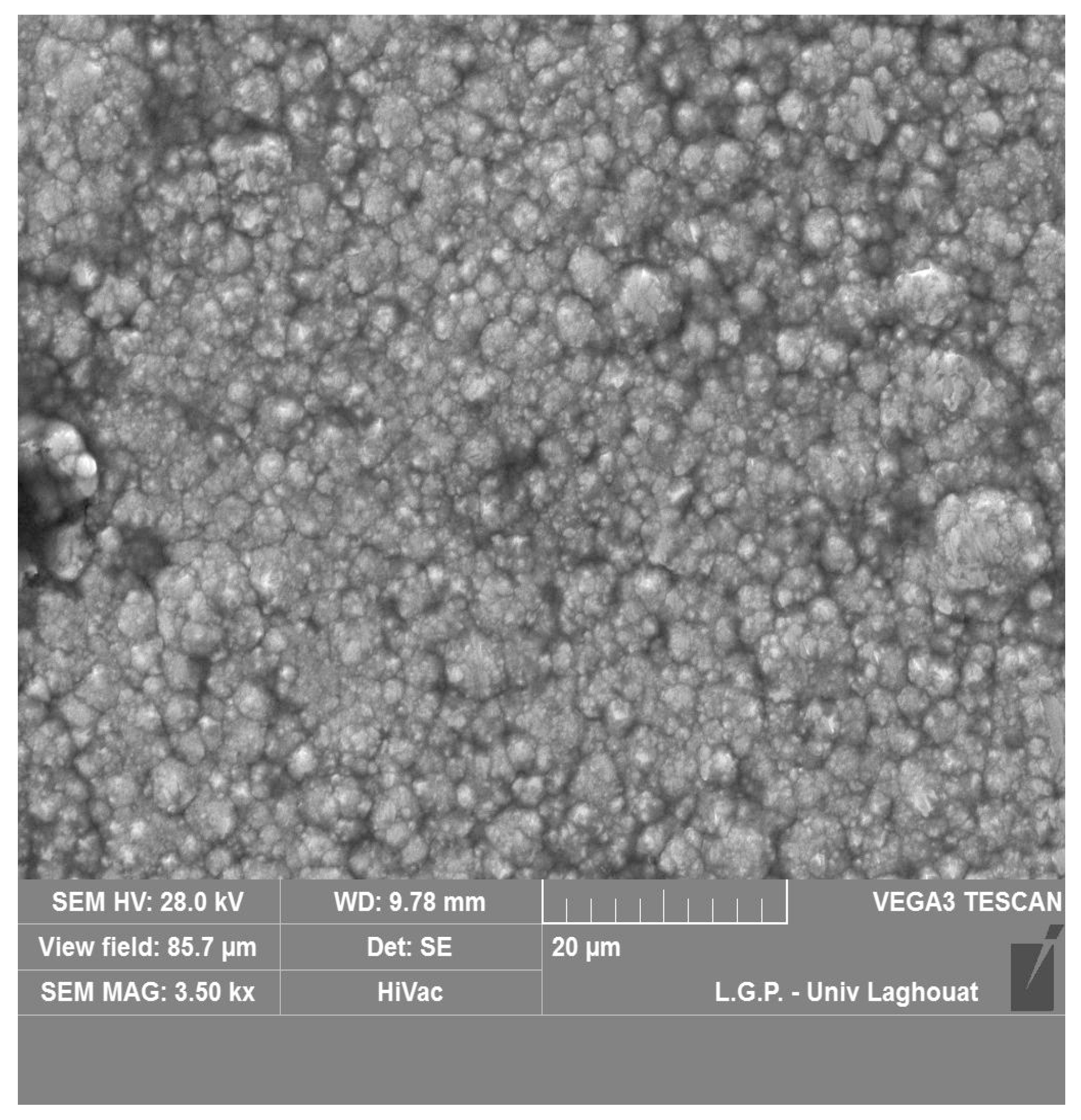
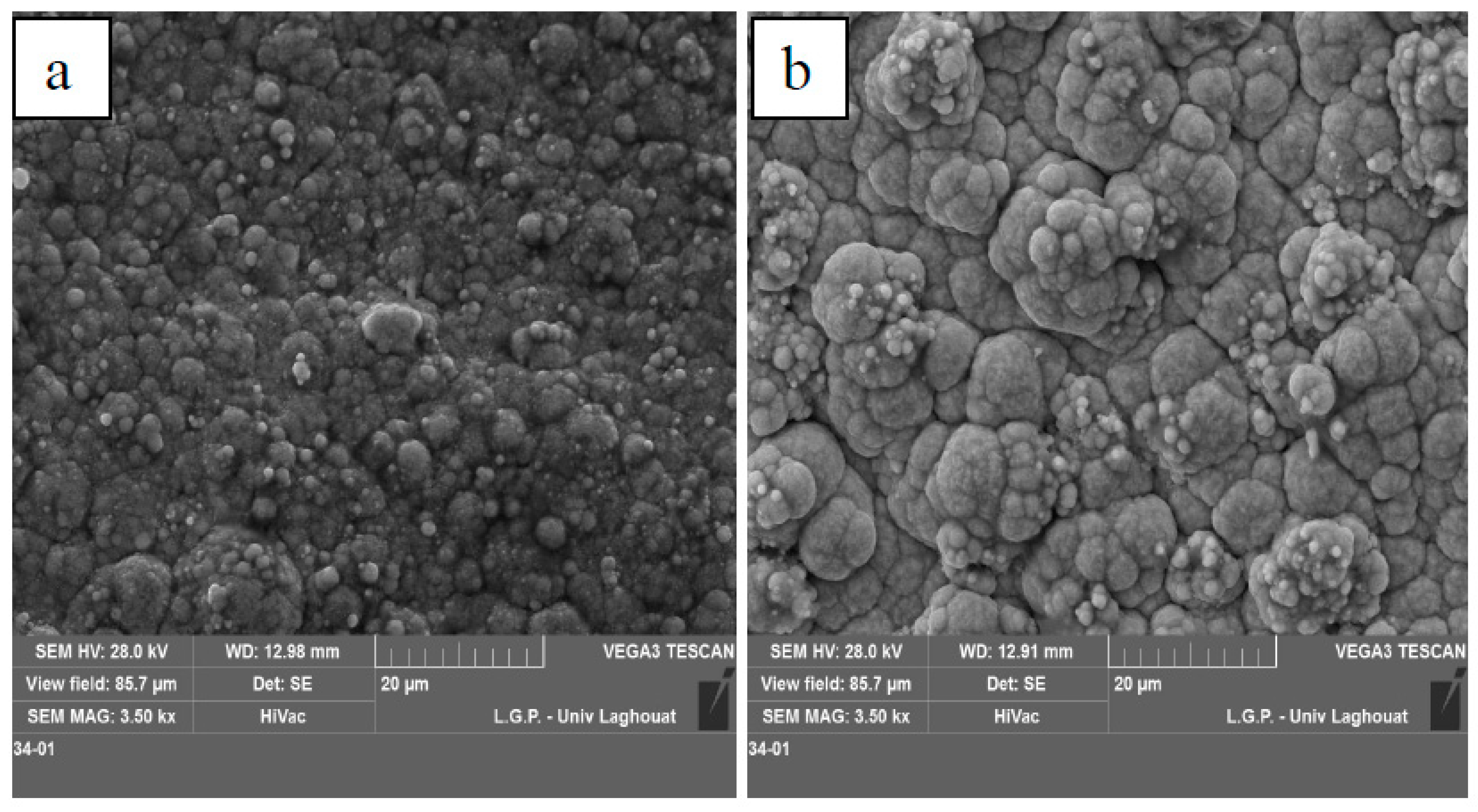
3.2.2. Surface Observation

Figure 5 presents the surface SEM image of the electrodeposited nickel film. It shows a compact nickel coating and that is composed of grains covering the entire surface with a “cauliflower” growth appearance.
Figure 6 displays the SEM surface images of the electrodeposited nickel film on copper with the addition of 5 g/L of TiO2 (Figure 6a) and 10 g/L of TiO2 (Figure 6b). In addition, EDS analysis of the surfaces (Figure 7) confirmed the existence of Ti in the nickel film. For the high concentration of TiO2 incorporated in the electrolytic bath (10 g/L), the first deposited grains on the substrate seem to have a larger size while the final deposit shows small grains of “cauliflower” shape.
Figure 8 shows the SEM image and the gnidnopserroc EDS mappings of Ni, Ti, and O elements for the Ni-TiO2 composite coatings. The elements are displayed as colored spots in the images. Ni (blue color) and TiO2 (Ti: green color; O: red color) seem homogeneously distributed on the surface, even if it is a rough surface. Similar mapping images were obtained for other photocatalysts, showing that the preparation method has successfully incorporated Ni and TiO2. However, it seems that some isolated agglomerations of O2 and Ti are observed. Our observations are in agreement with the research work performed on Ni-W-TiB2 composite coating [33]. From EDS mapping spectra of Ni-W-TiB2 composite coating, these elements (Ni, W, Ti, and B) are present throughout the surface. In addition, it has been reported that a distribution of these ultrafine particles in composite coatings becomes a crucial problem [6].

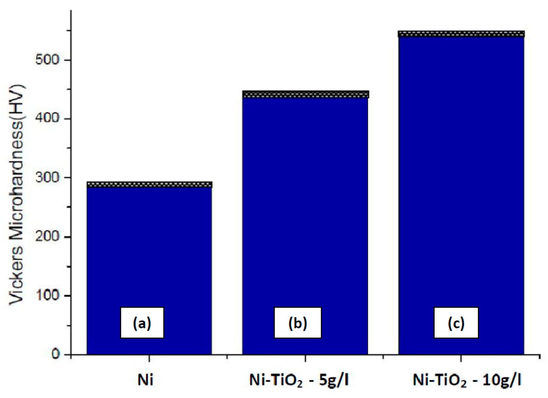
3.3. Microhardness Measurements
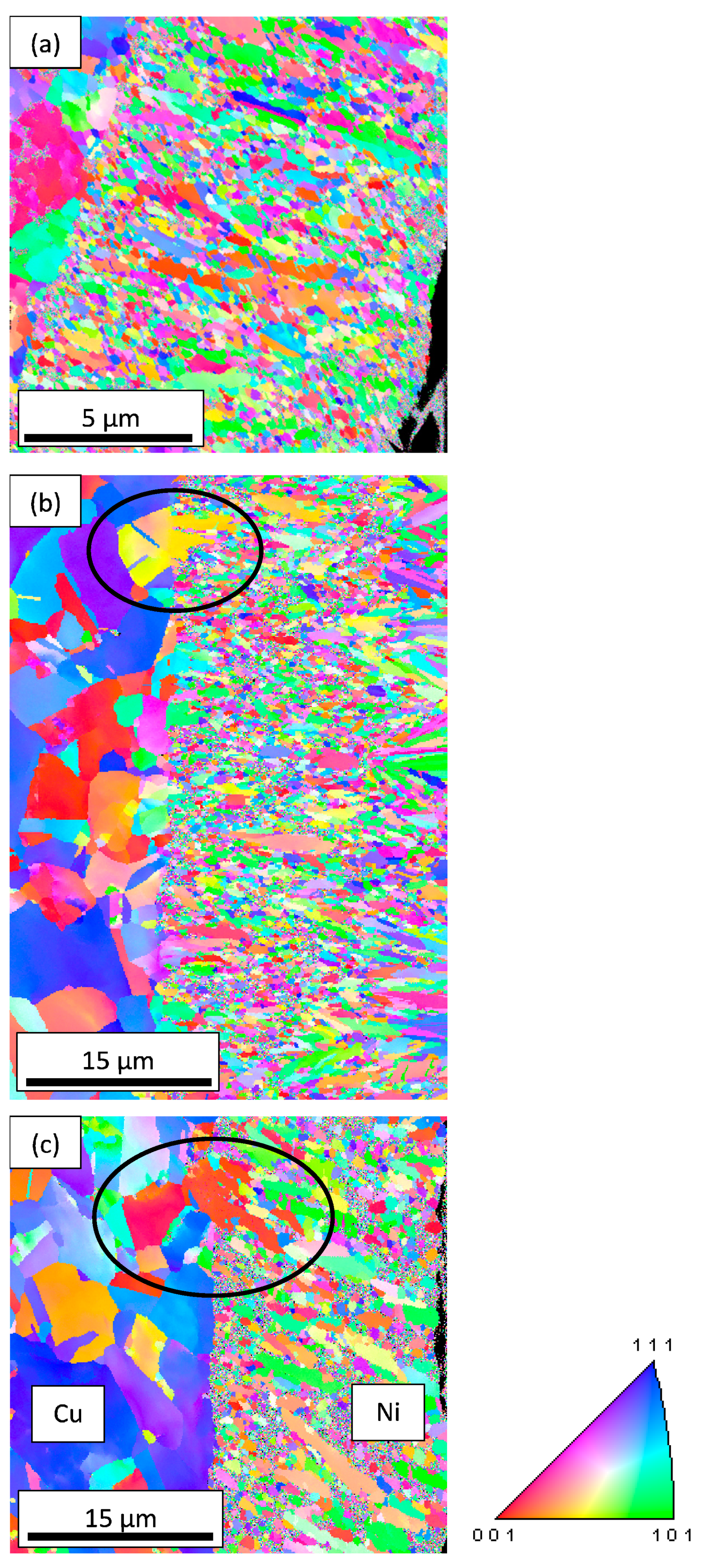
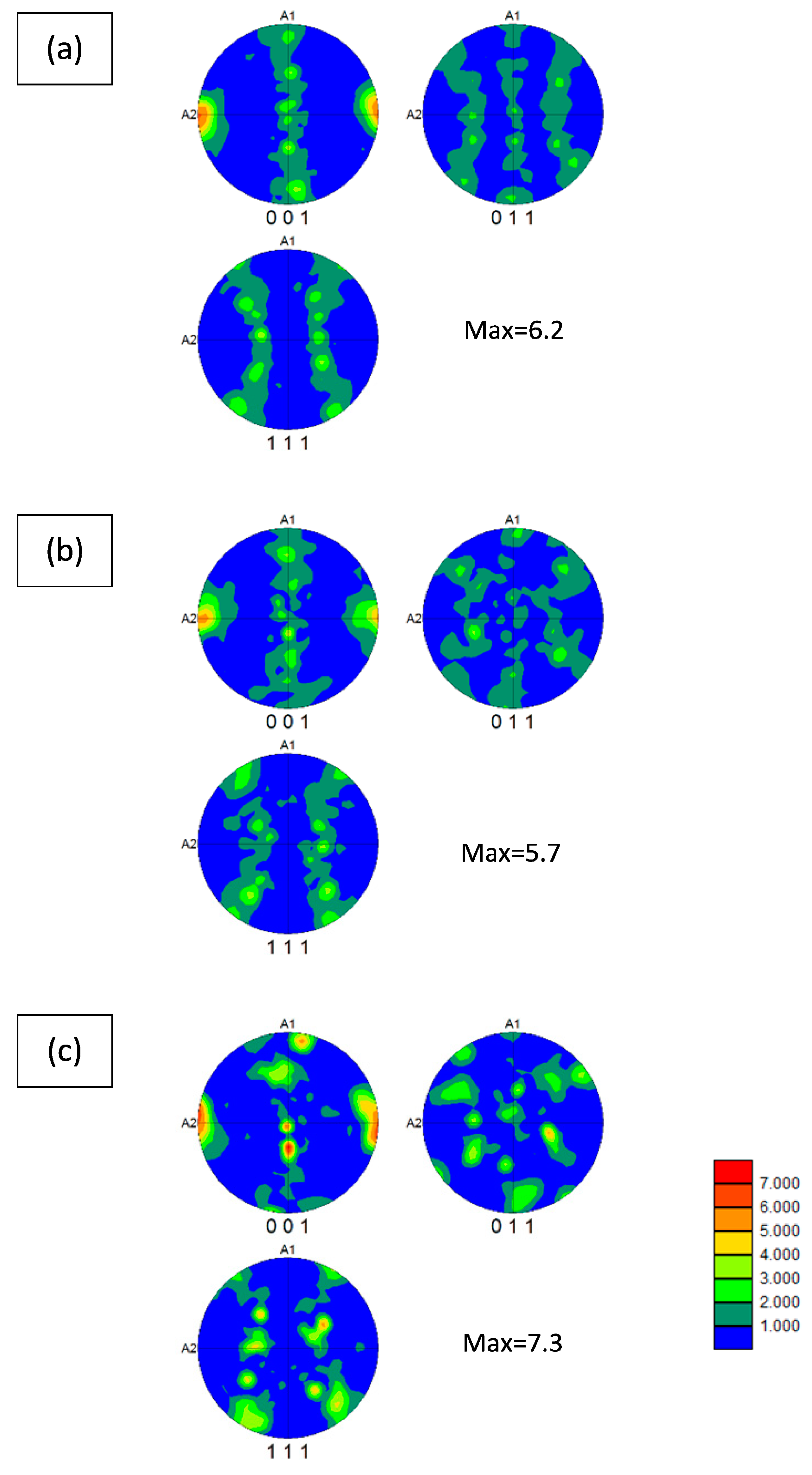
Vickers microhardness of the coated samples is shown in Figure 9. The Vickers microhardness of composite deposit Ni-layer coating is higher than the pure nickel coating. The incorporation of TiO2 in the deposit Ni-layer is one of the reasons to increase microhardness of the coatings. Further increase in microhardness of deposit Ni-layer by the incorporation of TiO2 is also clearly observed.

3.4. EBSD Analysis

EBSD analysis of the electrodeposited Ni on copper without and with the addition of TiO2 was carried out and corresponding EBSD orientation maps are presented in Figure 10. EBSD inverse pole figure map, showing in color code the orientation of the observation direction (A3, from Figure 2) in the crystal coordinate system. The color of individual grains describes the {hkl} crystallographic plane parallel to the observation plane. These EBSD maps give a general view on both grain morphology and orientation. Some nickel grains are indicated by a circle in Figure 10b,c formed in continuity of copper grains, these first primary grains are developed by epitaxial deposition. The average grain size of the deposited layer did not vary with the incorporation of TiO2 and it can be estimated at 0.5 μm. However, some limited number of large grains were formed with the incorporation of TiO2 in the nickel layer (Figure 10b,c).
The three poles figures presented in Figure 11 highlight the texture of the electrodeposited Ni on copper with and without addition of TiO2 and put in front to the same fiber <100> // A2 texture (the <100> crystallographic directions are parallel to the A2 axis of the sample reference) with quite the same acuity. Indeed, we note on the one hand that little differences exist between the pole figure intensities and on the other hand that the fibers are not perfect probably because the total number of studied grains is low. This is particularly observed in Figure 11c.

4. Discussions

The X-ray patterns of the electrodeposited Ni on copper with the addition of TiO2 nanoparticles indicate a preferred orientation (texture) of the nickel grain growth due to the lower strain in this direction as indicated by Gyawali et al. [33]. The incorporation of TiO2 nanoparticles has changed the regular growth of crystallites. This result is in agreement with the one of Mohajeri et al. [34]. In addition, Lajevardi and Shahrabi [35] found <100> fiber orientation at low pulse frequency by incorporation of TiO2 nanoparticles.
SEM observations reveal agglomeration of TiO2 nanoparticles in the coated copper. It has been found that these Ti-O2 nanoparticles are frequently agglomerated in the metal matrix due to their significant high surface energy [36,37,38]. In addition, surface observation has shown grains with a “cauliflower” appearance, as mentioned by Goranova et al. [39]. Moreover, TiO2 affects the surface morphology of the coated copper, by causing a top rougher surface [40]. This finding corroborates the observations made by Stankovic et al. [41], as they found that the surface roughness of the Ni-TiO2 composite coatings increases with increasing concentration of TiO2 particles. At the maximum amount of TiO2 added to the plating bath, the agglomerated particles propagated perpendicular on the cathode surface from big size agglomerations and ended with by particles of smaller size at the final external surface. Magdy et al. [42] and Gyawali et al. [33] have observed the same phenomenon respectively for MoS2 reinforcement particles into electrodeposited Ni-W alloy coating and for the incorporation of TiB2 submicron sized particles into the Ni-W alloy coating. They attributed this roughness to the presence of the coating different microstructures. Therefore, the enhancement of microhardness of Ni-TiO2 composite coating can be attributed to the dispersion hardening effect of reinforced TiO2 particles.
EDS mapping images confirmed the difficulty to achieve a homogeneous distribution of TiO2 in Ni-coatings, because research related to Ni-TiO2 composite coatings has demonstrated that the codeposition percentage of nano-titania particles is difficult to be controlled quantitatively, because the particles are frequently agglomerated in the metal matrix, as well as in the electrolyte [36,43] due to their significant high surface energy.
EBSD analysis of the electrodeposited Ni on copper without and with the addition of TiO2 has revealed epitaxial deposition. This mechanism is the most frequent during initial stage of electro-deposition. Then, grain growth generates new columnar grains in the growth direction of the deposit. EBSD results indicate a <100> // A2 fiber texture for all samples with or without TiO2-nanoparticles. According to Amblard and Froment [31], two main opposite theories have been used to describe the anisotropy of the texture of Nickel electrodeposited. The first theory suggests that the competition in nucleation is responsible for the anisotropy while the second one says that it is the competitive growth that determines the anisotropy. However, both theories are insufficient to fully describe all experimental results. This means that this research point needs further investigation.

5. Conclusions

In this work, the effect of TiO2-nanoparticles on Ni electrodeposition on copper wire has been studied. From this investigation, the following conclusions have been outlined:
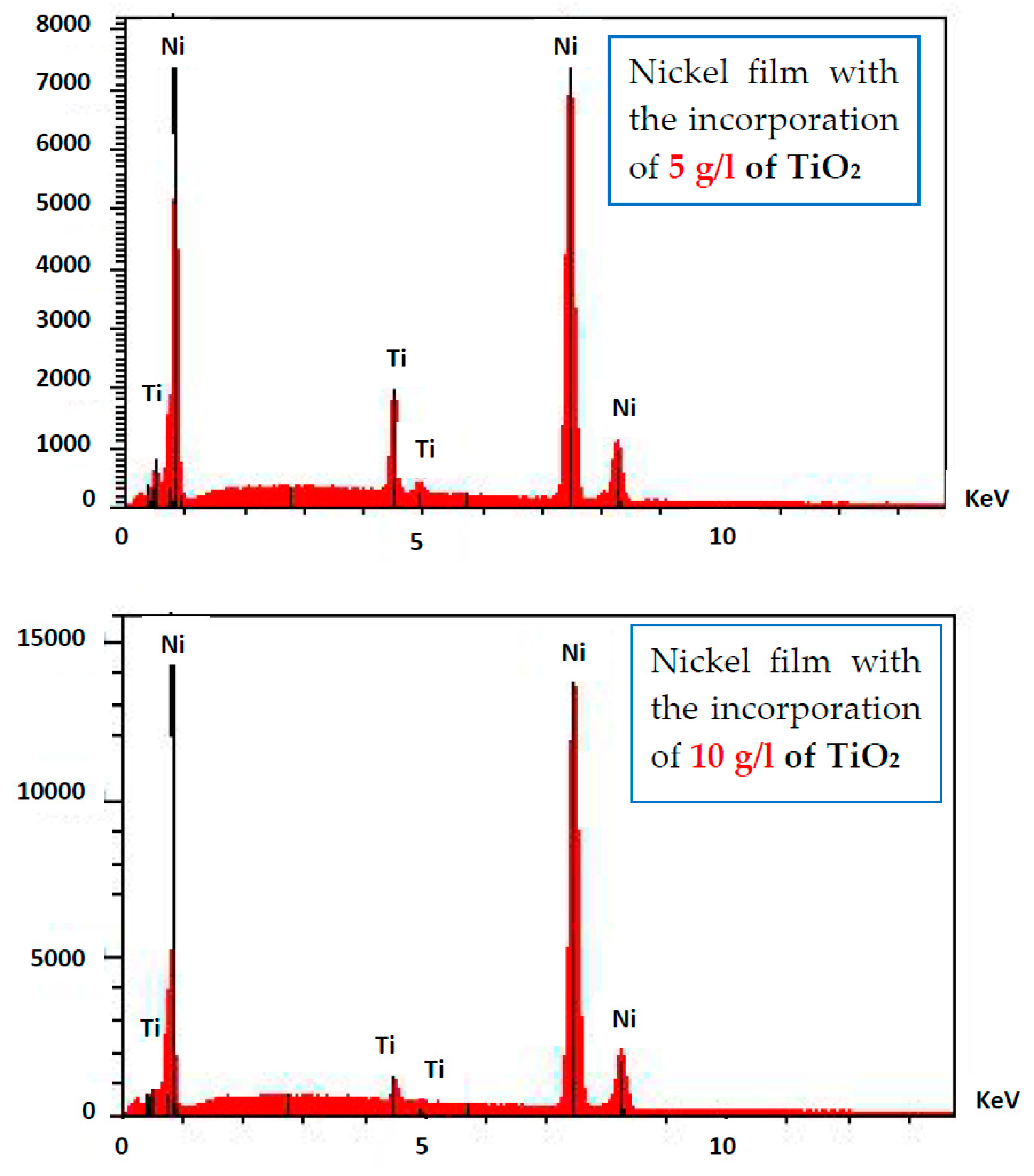
  • TiO2 nanoparticles can be successfully co-deposited with Ni matrix from a Watt bath.
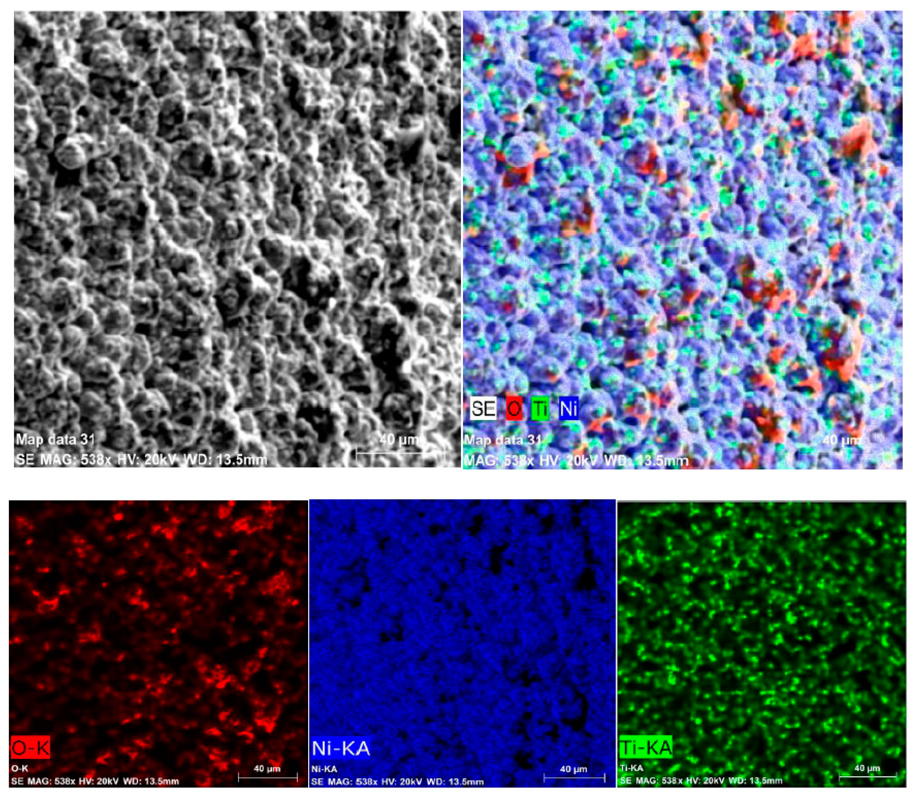
  • TiO2 nanoparticles are homogeneously distributed into the Ni matrix.
  • From the X-ray results, Ni grains have preferred orientation with the addition of TiO2 nanoparticles.
  • TiO2 nanoparticles cause a rougher surface.
  • Some limited number of large grains was formed with the incorporation of TiO2 in the nickel layer
  • At the maximum amount of TiO2 added (10 g/L), the agglomerated particles propagated perpendicularly to the cathode surface from big size agglomerations to particles of smaller size to the external surface.
  • The enhancement of microhardness of Ni-TiO2 composite coating can be attributed to the dispersion hardening effect of reinforced TiO2 particles.
  • EBSD results indicate a <100> // A2 fiber texture for all samples with or without TiO2-nanoparticles. This crystallographic direction corresponds to the Ni grain growth one.

Author Contributions

S.S. and Z.B. conceived and designed the experiments; S.S., T.B., F.B. and A.L.H. performed the experiments; Z.B., and T.B. analyzed the data; S.S., Z.B., and T.B. contributed materials; Z.B. wrote the paper; Z.B., T.B., F.B. and A.L.H. revised the paper. All authors have read and agreed to the published version of the manuscript.

Funding

This research received no external funding.

Conflicts of Interest

The authors declare no conflict of interest.

References

  1. Erb, U. Electrodeposited nanocrystals: Synthesis, properties and industrial applications. Nanostruct. Mater. 1995, 6, 533–538. [Google Scholar] [CrossRef]
  2. Cheung, C.; Djuanda, F.; Erb, U.; Palumbo, G. Electrodeposition of nanocrystalline Ni-Fe alloys. Nanostruct. Mater. 1995, 5, 513–523. [Google Scholar] [CrossRef]
  3. Wu, G.; Li, N.; Zhou, D.; Mitsuo, K. Electrodeposited Co–Ni–Al2O3 composite coatings. Surf. Coat. Technol. 2004, 176, 157–164. [Google Scholar] [CrossRef]
  4. Clark, D.; Wood, D.; Erb, U. Industrial applications of electrodeposited nanocrystals. Nanostruct. Mater. 1997, 9, 755–758. [Google Scholar] [CrossRef]
  5. Rastogi, M.C. Surface and Interfacial Science, Applications to Engineering and Technology, 1st ed.; Narosa Publishing House: New Delhi, India, 2003. [Google Scholar]
  6. Gul, H.; Kilic, F.; Aslan, S.; Alp, A.; Akbulut, H. Characteristics of electro-co-deposited Ni–Al2O3 nano-particle reinforced metal matrixcomposite (MMC) coatings. Wear 2009, 267, 976–990. [Google Scholar]
  7. Du, L.; Xu, B.; Dong, S.; Yang, H.; Tu, W. Study of tribological characteristics and wear mechanism of nano-particle strengthened nickel-based composite coatings under abrasive contaminant lubrication. Wear 2004, 257, 1058–1063. [Google Scholar] [CrossRef]
  8. Zimmerman, A.F.; Palumbo, G.; Aust, K.T.; Erb, U. Mechanical properties of nickel silicon carbide nanocomposites. Mater. Sci. Eng. A 2002, 328, 137–146. [Google Scholar] [CrossRef]
  9. Baghery, P.; Farzam, M.; Mousavi, A.B.; Hosseini, M. Ni–TiO2 nanocomposite coating with high resistance to corrosion and wear. Surf. Coat. Technol. 2010, 204, 3804–3810. [Google Scholar] [CrossRef]
  10. Chen, X.H.; Chen, C.S.; Xiao, H.N.; Cheng, F.Q.; Zhang, G.; Yi, G.J. Corrosion behavior of carbon nanotubes–Ni compositecoating. Surf. Coat. Technol. 2005, 191, 351–356. [Google Scholar]
  11. Stroumbouli, M.; Gyftou, P.; Pavlatou, E.A.; Spyrellis, N. Codeposition of ultrafine WC particles in Ni matrix composite electrocoatings. Surf. Coat. Technol. 2005, 195, 325–332. [Google Scholar] [CrossRef]
  12. Aruna, S.T.; William, V.K.; Rajam, K.S. Ni-based electrodeposited composite coating exhibiting improved microhardness, corrosion and wear resistance properties. J. Alloys Com. 2009, 468, 546–552. [Google Scholar] [CrossRef]
  13. Wojciechowski, J.; Baraniak, M.; Pernak, J.; Lota, G. Nickel coatings electrodeposited from Watts type baths containing quaternary ammonium sulphate Salts. Int. J. Electrochem. Sci. 2017, 12, 3350–3360. [Google Scholar] [CrossRef]
  14. Tilak, B.V.; Gendron, A.S.; Mosoiu, M.A. Borate buffer equilibria in nickel refining electrolytes. J. Appl. Electrochem. 1977, 7, 495–500. [Google Scholar] [CrossRef]
  15. Cui, C.Q.; Lee, J.Y. Nickel deposition from unbuffered neutral chloride solutions in the presence of oxygen. Electrochim. Acta 1995, 40, 1653–1662. [Google Scholar] [CrossRef]
  16. Tian, B.R.; Cheng, Y.F. Electrolytic deposition of Ni–Co–Al2O3 composite coating on pipe steel for corrosion/erosion resistance in oil sand slurry. Electrochim. Acta 2007, 53, 511–517. [Google Scholar] [CrossRef]
  17. Gvozden, T.; Sladjana, M.; Dragana, Z.; Aleksandar, D.M.; Milica P., M.K. Characterization of the Ni–Mo catalyst formed in situ during hydrogen generation from alkaline water electrolysis. Int. J. Hydrogen Energy. 2011, 36, 11588–11595. [Google Scholar]
  18. Vereecken, P.M.; Shao, I.; Searson, P.C. Particle Codeposition in Nanocomposite Films. J. Electrochem. Soc. 2002, 147, 2572. [Google Scholar] [CrossRef]
  19. Ben Temam, H.; Chala, A.; Rahmane, S. Microhardness and corrosion behavior of Ni–SiC electrodeposited coatings in presence of organic additives. Surf. Coat. Technol. 2011, 205, S161–S164. [Google Scholar] [CrossRef]
  20. Indyka, P.; Beltowska-Lehman, E.; Tarkowski, L.; Bigos, A.; García-Lecina, E. Structure characterization of nanocrystalline Ni–W alloys obtained by electrodeposition. J. Alloys Compd. 2014, 590, 75–79. [Google Scholar] [CrossRef]
  21. Calleja, P.; Esteve, J.; Cojocaru, P.; Magagnin, L.; Vallés, E.; Gómez, E. Developing plating baths for the production of reflective Ni–Cu films. Electrochim. Acta 2012, 62, 381–389. [Google Scholar] [CrossRef]
  22. Jovic, B.M.; La cnjevac, U.C.; Krstaji, N.V.; Jović, V.D. Ni–Sn coatings as cathodes for hydrogen evolution in alkaline solutions. Electrochim. Acta 2013, 114, 813. [Google Scholar] [CrossRef]
  23. Abdel-Karim, R.; Halim, J.; El-Raghy, S.; Nabil, M.; Waheed, A. Surface morphology and electrochemical characterization of electrodeposited Ni–Mo nanocomposites as cathodes for hydrogen evolution. J. Alloys Compd. 2012, 530, 85–90. [Google Scholar] [CrossRef]
  24. Sanches, L.S.; Domingues, S.H.; Marino, C.E.; Mascaro, H.M. Characterisation of electrochemically deposited Ni–Mo alloy coatings. Electrochem. Commun. 2004, 6, 543–548. [Google Scholar] [CrossRef]
  25. Spanou, S.; Pavlatou, E.A.; Spyrellis, N. Ni/nano-TiO2 Composite Electrodeposits:Textural and Structural Modifications. Electrochim. Acta 2008, 54, 2547–2555. [Google Scholar] [CrossRef]
  26. Malatji, N.; Popoola, P.A.I. Tribological and Corrosion Performance of Electrodeposited Nickel Composite Coatings, Chapter 10, Electrodeposition of Composite Materials, 1st ed.; IntechOpen: Rijeka, Croatia, 2016. [Google Scholar]
  27. Duan, G.; Cai, W.; Luo, Y.I. Transferable ordered Ni hollow sphere arrays induced by electrodeposition on colloidal monolayer. Phys. Chem. B 2006, 110, 14–7184. [Google Scholar] [CrossRef]
  28. Yılmaz, G.; Hapcı, G.; Orhan, G. Properties of Ni/Nano-TiO2 composite coatings prepared by direct and pulse current electroplating. JMEPEG 2015, 24, 709–720. [Google Scholar] [CrossRef]
  29. Benea, L.; and Danaila, E. Nucleation and growth mechanism of Ni/TiO2 nanoparticles electro-codeposition. J. Electrochem. Soc. 2016, 163, D655–D662. [Google Scholar] [CrossRef]
  30. Kolonits, T.; Czigány, Z.; László Péter, L. Influence of Bath Additives on the Thermal Stability of the Nanostructure and Hardness of Ni Films Processed by Electrodeposition. Coatings 2019, 9, 644. [Google Scholar] [CrossRef] [Green Version]
  31. Amblard, J.; Froment, M. New interpretation of texture formation in nickel electrodeposits. Faraday Symp. Chem. Soc. 1977, 12, 136–144. [Google Scholar]
  32. Bhushan, B. Surface roughness analysis and measurement techniques. In Modern Tribology Handbook; CRC Press LLC: New York, NY, USA, 2001. [Google Scholar]
  33. Gyawali, G.; Tripathi, K.; Joshi, B.; Lee, S.W. Mechanical and tribological properties of Ni-W-TiB2 composite coatings. J. Alloys Compd. 2017, 721, 757–763. [Google Scholar] [CrossRef]
  34. Mohajeri, S.; Dolati, A.; Ghorbani, M. The influence of pulse plating parameters on the electrocodeposition of Ni-TiO2 nanocomposite single layer and multilayer structures on copper substrates. Surf. Coat. Technol. 2015, 262, 173–183. [Google Scholar] [CrossRef]
  35. Lajevardi, S.A.; Shahrabi, T. Effects of pulse electrodeposition parameters on the properties of Ni–TiO2 nanocomposite coatings. Appl. Surf. Sci. 2010, 256, 6775–6781. [Google Scholar] [CrossRef]
  36. Lampke, T.; Wielage, B.; Dietrich, D.; Leopold, A. Details of crystalline growth in co-deposited electroplated nickel films with hard (nano) particles. Appl. Surf. Sci. 2006, 253, 2399–2408. [Google Scholar] [CrossRef]
  37. Thiemig, T.; Bund, A. Characterization of electrodeposited Ni–TiO2 nanocomposite coatings. Surf. Coat. Technol. 2008, 202, 2976–2984. [Google Scholar] [CrossRef]
  38. Lampe, T.; Leopold, A.; Dietrich, D.; Alisch, G.; Wielage, B. Correlation between structure and corrosion behaviour of nickel dispersion coatings ceramic particles of different sizes. Surf. Coat. Technol. 2006, 201, 3510–3517. [Google Scholar] [CrossRef]
  39. Goranova, D.; Avdeev, G.; Rashkov, R. Electrodeposition and characterization of Ni–Cu alloys. Surf. Coat. Technol. 2014, 240, 204–210. [Google Scholar] [CrossRef]
  40. Cardinal, M.F.; Castro, P.A.; Baxi, J.; Liang, H.; Williams, F.J. Characterization and frictional behavior of nanostructured Ni–W–MoS2 composite coatings. Surf. Coat. Technol. 2009, 204, 85–90. [Google Scholar] [CrossRef]
  41. Stankovic, V.; Gojo, M.; Grekulovic, V.; Pajkić, N.; Cigula, T. Surface quality of the Ni-TiO2 composite coatings produced by electroplating. J. Min. Metall. Sect. B Metal. 2017, 53, 341–348. [Google Scholar] [CrossRef]
  42. Magdy, A.M.; Ibrahim Kooli, F.; Saleh, N. Electrodeposition and characterization of nickel-TiN microcomposite coatings. Int. J. Electrochem. Sci. 2013, 8, 12308–12320. [Google Scholar]
  43. Erler, F.; Jakob, C.; Romanus, H.; Spiess, L.; BWielage, L.; Lampke, T.; Steinhäuser, S. Interface behavior in nickel composite coatings with nano-particles of oxidic ceramic. Electrochim. Acta. 2003, 48, 3063. [Google Scholar] [CrossRef]
Figure 1. Schematic representation of the electroplating cell (R: Resistance; A: Ampermeter; V: Voltmeter).
Metals 10 00406 g001
Figure 2. Schematic illustration of the transverse cross section of samples with the coordinate system.
Metals 10 00406 g002
Figure 3. X-ray patterns of the electrodeposited Ni on copper (a) without and with the addition of TiO2, (b) 5 g/L of TiO2, (c) and 10 g/L of TiO2.
Metals 10 00406 g003
Figure 4. SEM observations of the electrodeposited Ni on Cu (a) without and (b) with the addition of 5g/L of TiO2.
Metals 10 00406 g004
Figure 5. Surface SEM image of the electrodeposited nickel film.
Metals 10 00406 g005
Figure 6. Surface SEM images of the electrodeposited nickel film with the incorporation of (a) 5 g/L of TiO2, (b) 10 g/L of TiO2.
Metals 10 00406 g006
Figure 7. Energy dispersive X-ray spectrometry (EDS) Spectra of the electrodeposited Ni–TiO2 alloys (5 g/L of TiO2 and 10 g/L of TiO2).
Metals 10 00406 g007
Figure 8. EDS mappings of Ni, Ti, and O elements for the Ni–TiO2 composite coatings (5 g/L of TiO2).
Metals 10 00406 g008
Figure 9. Vickers microhardness of the electrodeposited Ni on copper (a) without and with the addition of TiO2, (b) 5 g/L of TiO2, (c) 10 g/L of TiO2.
Metals 10 00406 g009
Figure 10. Electron backscatter diffraction (EBSD) orientation color maps of the electrodeposited Ni on copper (a) without and with the addition of TiO2, (b) 5 g/L of TiO2, (c) 10 g/L of TiO2. (The crystallographic direction is perpendicular to the observation plane A1–A2).
Metals 10 00406 g010
Figure 11. Pole figures of the electrodeposited Ni on copper (a) without and with the addition of TiO2, (b) 5 g/L of TiO2, (c) 10 g/L of TiO2.
Metals 10 00406 g011

