Abstract
The effects of arc modes on laser-arc hybrid welding for AA6082-T6 aluminum alloy were comparatively studied. Two arc modes were employed: pulsed metal inert gas arc and cold metal transfer arc. The results indicated that joints without porosity, undercutting, or other defects were obtained with both laser-pulsed metal inert gas hybrid welding (LPMHW) and laser-cold metal transfer hybrid welding (LCHW). Spatter was reduced, and even disappeared, during the LCHW process. The sizes of equiaxed dendrites and the width of the partially melted zone in the LPMHW joint were larger than those in the LCHW joint. The microhardness in each zone of the LPMHW joint was lower than that of the LCHW joint. The softening region in the heat-affected zone of the LPMHW joint was wider than that of the LCHW joint. The tensile strength of the LCHW joint was higher than that of the LPMHW joint. For the two joints, the fractures all occurred in the softening region in the heat-affected zone, and the fracture morphologies showed ductile fracture features. The dimples in the fractograph of the LCHW joint were deeper than those of the LPMHW joint.
1. Introduction
The application of lightweight materials is one of the most strategic approaches to increase the operational speed of delivery vehicles. In the high-speed train manufacturing industry, Al-Mg-Si (6xxx series) alloys have been widely applied as lightweight materials for many years because of their excellent specific strength, weldability, and corrosion resistance [1,2]. Generally, aluminum alloys are joined by arc welding, especially metal inert gas (MIG) welding. Considering the physical-chemical characteristics of aluminum alloys, numerous results indicate that some obvious drawbacks such as: large welding deformation, serious joint softening, and low production efficiency would appear during the arc welding process due to the high heat input and low welding speed [3,4,5]. With features of high energy density, low heat input, high welding speed, and large depth–width ratio, laser welding can effectively solve the above problems [6,7,8,9]. However, strict accuracy in assembly is required due to the small focused spot diameter of the laser, which significantly limits its application [10,11].
Laser-arc hybrid welding (LAHW) combines the advantages of laser welding and arc welding, which not only can reduce or even eliminate common weld defects but can also increase the laser’s energy utilization. Therefore, it is becoming an important welding technology for joining aluminum alloys, especially for laser-pulsed MIG hybrid welding (LPMHW) [12,13,14]. Compared with laser welding and arc welding, previous research proved that LPMHW has several advantages, such as: higher welding speed [15], deeper weld penetration [16], narrower heat-affected zones [17], better gap bridging ability [18], less residual stress [19], and superior mechanical properties [20]. Meanwhile, some research pointed out that welding deformation due to high heat input was still unignorable, and that spatter could not be completely eliminated due to the droplet transfer mode [21,22], which was determined by the arc characteristic of pulsed MIG welding.
A modified MIG welding technology called cold metal transfer (CMT) welding was developed by Fronius of Austria in 2004 [23]. Different from pulsed MIG welding, the droplet is detached by retracting the wire and transferred in a short-circuit mode during the CMT welding process, and it was indicated that CMT welding could reduce heat input and improve weld stability [24,25,26]. Obviously, integrating a CMT arc rather than a PMIG arc with a laser beam will reduce the heat input of laser-arc hybrid welding. Recently, researchers have begun to focus on the effects of the arc modes on LAHW characteristics. Lamas et al. [27] indicated that the CMT mode had higher welding speeds, less heat input, and fewer undercut defects compared to other arc modes during LAHW for high strength steel. Li et al. [28] pointed out that compared with the LPMHW process for mild steel, the plasma was more stable and the spatter was less in the laser-CMT hybrid welding (LCHW) process. Few reports have focused on the effects of arc mode on the characterizations of LAHW for aluminum alloys. Zhang et al. [29] indicated that an LCHW AA6061 joint had a finer microstructure and higher tensile strength compared with that of an LPMHW joint. With so many novel advantages, laser-CMT hybrid welding could be a promising joining technology for high speed train aluminum body manufacturing, and needs further understanding.
In the present work, two kinds of laser-arc hybrid welding (LAHW), including laser-pulsed MIG hybrid welding (LPMHW) and laser-CMT hybrid welding (LCHW), were performed upon 6 mm thick AA6082-T6 aluminum alloy butt joints using optimized welding parameters. The effects of the arc modes on weld formation, microstructure, microhardness, and mechanical properties were comparatively studied in detail.
2. Materials and Experimental Details
2.1. Materials
In this work, the base material used was AA6082-T6 aluminum alloy with a thickness of 6 mm. The tensile strength of the base material was 310 MPa. The sheets were machined to the size of 200 mm × 150 mm × 6 mm, and a Y-shaped groove was machined as shown in Figure 1. Before welding, the base materials were preprocessed using mechanical cleaning followed by scrubbing. The filler wire used was ER5356 with a diameter of 1.2 mm. The chemical compositions of the base material and filler wire are presented in Table 1.
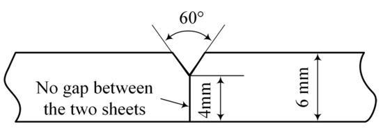
Figure 1.
Schematic diagram of the welding groove type.

Table 1.
Chemical compositions of materials (wt. %).
2.2. Welding Method and Apparatus
The LAHW experiments were conducted with an IPG YLS-6000 fiber laser (Burbach, Germany) (maximum output power is 6.0 kW) in combination with a Fronius TPS 500i CMT welding machine (Wels, Austria) (with two arc modes: pulsed arc mode and CMT arc mode), which were controlled by a KUKA 30 HA (Bavaria, Germany) high precision welding robot. The emission wavelength and focus diameter of the laser were 1.06 μm and 0.2 mm, respectively. The Rayleigh length of the laser beam was about 1.8 mm. The system configuration and schematic diagram of the LAHW experimental setups are illustrated in Figure 2.
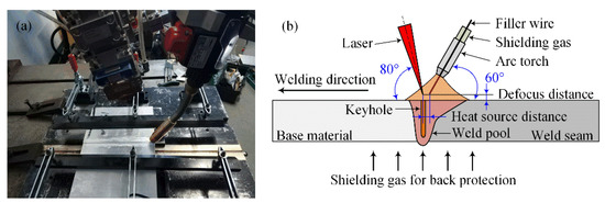
Figure 2.
(a) System configuration and (b) schematic diagram (not to scale) of the laser-arc hybrid welding (LAHW) experimental setups.
During the LAHW process, the sheets were fixed using a clamping fixture. The copper center of the clamping fixture had holes 1.0 mm in diameter and spaced 8 mm apart, which were used to blow shielding gas for back protection, as shown in Figure 2a. High purity argon (99.999%) with flow rates of 20 L/min and 15 L/min was used as a shielding gas for the arc torch and back protection, respectively. To protect the optical fiber and improve the coupling effect of the laser and arc, the oblique angles of the laser and arc torch from the workpiece were 80° and 60°, respectively, as shown in Figure 2b. The distance between the laser beam and wire tip was 3 mm, and the defocus distance of the laser beam was 2 mm. After numerous welding experiments, according to weld formation quality, the other optimized welding parameters of LPMHW and LCHW used in this work are listed in Table 2.
Table 2.
The welding parameters of laser-pulsed metal inert gas hybrid welding (LPMHW) and laser-cold metal transfer hybrid welding (LCHW).
2.3. Testing Examination
Metallographic samples were taken from the weld cross-section, then mechanically ground, polished, and finally etched with Keller’s reagent for about 10 s. Macromorphology and microstructure were observed by optical microscopy (OLYMPUS, BX-51M, Tokyo, Japan). The microhardness test was performed on the weld cross-section from the weld center to the base metal using a Vicker microhardness tester (FUTURE-TECH FM-700, Kawasaki, Japan) with a loading force of 100 g for 10 s. The tensile tests were performed at a loading rate of 2 mm/min using an electronic universal testing machine (STAR, WDW-300E, Jinan, China) according to GB/T 228.1-2010 [30], and the geometric dimensions of the tensile specimens are shown in Figure 3. The tensile strength was the average of three specimens. The fracture features were observed by a scanning electron microscope (ZEISS, SUPRA 55, Jena, Germany).
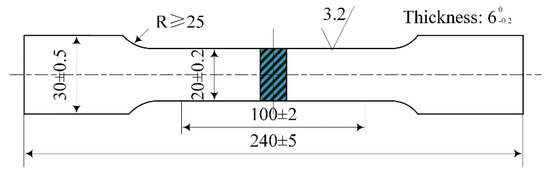
Figure 3.
Schematic diagram of specimens used for tensile testing.
3. Results and Discussion
3.1. Weld Formation
The weld cross-sections of the LPMHW and LCHW joints are presented in Figure 4. Both of them appeared hourglass-shaped and consisted of an arc zone and a laser zone [13,29,31], as shown in Figure 4a,b. For the sake of convenience, the typical zones and dimensions of the cross-section were defined as follows: Pa-weld penetration of the arc zone, Pl-weld penetration of the laser zone, Wf-weld width of the front surface, Wb-weld width of the back surface, Rf-reinforcement of the front surface, and Rb-reinforcement of the back surface, as described in Figure 4a.
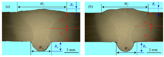
Figure 4.
Cross-sections of (a) the LPMHW joint and (b) the LCHW joint.
The measured results of the cross-section dimensions for the LPMHW and LCHW joints are listed in Table 3. The results indicate that joints without porosity, undercutting, or other apparent welding defects could be obtained with both the LPMHW and LCHW. Pa and Wf of the LPMHW joint were higher than that of the LCHW joint; on the contrary, Pl and Wb of the LPMHW joint were lower than that of the LCHW joint. The main reason was that the PMIG arc needed a higher heat input. Although the LPMHW had a higher wire feeding speed, the Rf of the LPMHW joint was lower than that of the LCHW joint with the same welding speed. This indicated that the CMT arc reduced the arc pressure on the weld pool, which was the other reason for the Pl of the LPMHW joint being higher than that of the LCHW joint [29]. The Rb of the LPMHW and LCHW joints were roughly the same because of the excellent fluidity of the liquid aluminum alloy.
Table 3.
Measured results of the cross-section dimensions for the LPMHW and LCHW joints.
Spatter was observed on the LPMHW specimen surface, while there was almost no spatter to be found on the LCHW specimen surface, as shown in Figure 5a,c. The effects of droplets on the keyhole directly influence the formation of spatter during the LAHW process [32]. The droplet transfer modes were a spray transfer mode and a short-circuiting transfer mode, respectively, as shown in Figure 5b,d. The interactions between the keyhole and the droplet were different during the LPMHW and LCHW processes, which led to the different quantities of spatter. In the case of short-circuiting transition, as well as the droplets being detached with the assistance of filler wire retraction, the effects of the droplets on the keyhole were substantially weakened, which made the weld pool more stable [25]. Therefore, compared with the LPMHW process, spatter was reduced, and even disappeared, during the LCHW process.
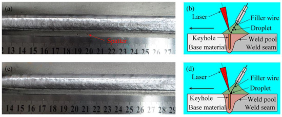
Figure 5.
Surface appearance of the LPMHW joint (a), droplet transfer mode during the LPMHW process (b), surface appearance of the LCHW joint (c), and droplet transfer mode during the LCHW process (d).
3.2. Microstructure Characteristics
The major focus of this part was the microstructure comparison in the arc zone of the LPMHW and LCHW joints, and the microstructural characteristics were as shown in Figure 6. The metallographic observation results showed that the LPMHW and LCHW joints had similar characteristics; five distinct zones existed from the weld center to the base material: an equiaxed zone, a columnar zone, a partially melted zone, an over-aged zone, and the base material, as shown in Figure 6a.
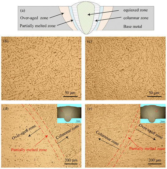
Figure 6.
(a) Diagrammatic drawing of the five distinct zones in the weld. Microstructure in the arc zone center of (b) the LPMHW joint and (c) the LCHW joint, and near the arc zone fusion line of (d) the LPMHW joint and (e) the LCHW joint.
Equiaxed dendrites were observed in the center of the arc zone for both the LPMHW and LCHW joints. In general, the equiaxed grains formed in the two joints were fine and uniform. Meanwhile, the comparison of results between Figure 6b,c indicated that the sizes of the equiaxed dendrites in the LPMHW joint were slightly larger than those in the LCHW joint. The main reason for this difference was that the heat input of the pulsed arc was slightly higher than that of the CMT arc during the welding process. Near the fusion line, parallel dendrites were preferentially elongated in the direction of the thermal gradient, and the heat-affected zone consisted of a partially melted zone and an over-aged zone, as shown in Figure 6d,e. However, there were two significant differences between the LPMHW and LCHW joints: firstly, the width of the partially melted zone in the LPMHW joint (about 97.2 μm) was larger than that in the LCHW joint (about 74.3 μm); secondly, the over-aged zone in the LCHW joint was not as obvious as that in the LPMHW joint. The different microstructures resulted from the different cooling rates and heat inputs [33,34]. A lower heat input during CMT arc mode was the main reason for these differences.
3.3. Microhardness Distribution
According to BS EN ISO 9015-2:2016 [35], the microhardness test positions were 1 mm and 5 mm away from the top surface of the joint, respectively. The microhardness distributions in the different areas of the LPMHW and LCHW joints are shown in Figure 7. For both of the two joints, the microhardness distribution presented inhomogeneity. The base material had the highest microhardness value, and the microhardness of the weld seam and the heat-affected zone decreased in different degrees. There were two main reasons for the microhardness decrease in the weld seam: firstly, the microhardness of the filler wire was lower than that of the base material; secondly, the alloying elements were burned and lost during the welding process [1,36]. That the grain size became larger and the precipitates became fewer were the causes of the microhardness decrease in the heat-affected zone [37].
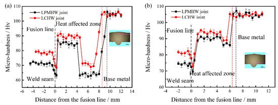
Figure 7.
Microhardness distributions (a) in the arc zone and (b) in the laser zone of the LAHW joints.
Overall, the microhardness values of each zone for the LPMHW joint were lower than that of the LCHW joint, and the microhardness values of the arc zone were also lower than that of the laser zone. By comparison, the width of the heat-affected zone of the LPMHW joint was larger than that of the LCHW joint. It was found that there were two softening regions in the affected zone of the two joints: one was in the partially melted zone because of the loss of strengthening alloying elements in this area [37,38], and the other was at a distance away from the fusion line due to the strengthening phases (β″) being dissolved and substantially decreased in this area [39]. Furthermore, the second softening region was more prominent in the arc zone, and was also wider for the LPMHW joint compared with that of the LCHW joint. All of the above phenomena were due to higher heat input during the LPMHW process.
3.4. Mechanical Properties
The tensile properties of the LPMHW and LCHW joints are listed in Table 4. It can be found that the average tensile strength of the LCHW joints reached up to 262.5 MPa and was higher than that of the LPMHW joints (255.1 MPa), and these strengths were 84.7% and 82.4% of the base material (310 MPa) used in this work, respectively.
Table 4.
Mechanical properties of the LPMHW and LCHW joints.
Fracture locations, macroscopic features, and microscopic fractures of the LPMHW and LCHW joints are shown in Figure 8. The fractures of the tensile specimens for the LPMHW and LCHW joints all occurred in the softening regions of the heat-affected zone, and the fracture propagation paths were almost parallel to the fusion line, as shown in Figure 8a,c. This result indicated that the softening region in the heat-affected zone was the weakest area. More serious softening was caused in the heat-affected zone of the LPMHW joint, as shown in Figure 7a; therefore, the average tensile strength of the LPMHW joint was slightly lower than that of the LCHW joint. The fracture morphologies indicated that the LPMHW and LCHW joints had similar fracture characteristics. For these two joints, the fractures were all characterized by dimples with a few second phase particles at the bottom of the dimples, as shown in Figure 8b,d. The fracture surfaces of the two joints showed a typical dimple fracture appearance revealing a ductile failure mode [21,31], but the dimples in the fractograph of the LCHW joint were deeper than those of the LPMHW joint.
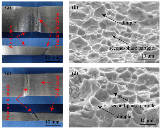
Figure 8.
(a) Fracture location and (b) microscopic fracture of the LPMHW joint, (c) fracture location and (d) microscopic fracture of the LCHW joint.
4. Conclusions
In the present work, a comparative study on the weld formation, microstructure, microhardness, and mechanical properties of laser-pulsed metal inert gas hybrid welding (LPMHW) and laser-cold metal transfer mode hybrid welding (LCHW) for 6 mm thick AA6082-T6 aluminum alloy was carried out in detail. The main conclusions can be summarized as follows:
(1) Joints without porosity, undercutting, or other welding defects could be obtained by both LPMHW and LCHW. Compared with the LPMHW process, the effects of the droplets on the keyhole were substantially weakened, which reduced, and even eliminated, spatter during the LCHW process.
(2) The microstructures of the LPMHW and LCHW joints both consisted of an equiaxed zone, a columnar zone, a partially melted zone, an over-aged zone, and the base material. Due to lower heat input during the LCHW process, the sizes of the equiaxed dendrites and the width of the partially melted zone in the LPMHW joint were slightly larger than that in the LCHW joint, and the over-aged zone in the LCHW joint was not as obvious as that in the LPMHW joint.
(3) The microhardness of each zone for the LPMHW joint was lower than that of the LCHW joint, and the microhardness of the arc zone was also lower than that of the laser zone for the two joints. By comparison, the heat-affected zone width of the LPMHW joint was larger than that of the LCHW joint. Two softening regions were identified in the partially melted zone and the heat-affected zone, and the latter was more prominent in the arc zone. The softening region in the heat-affected zone of the LPMHW joint was also wider than that of the LCHW joint.
(4) The average tensile strengths of the LPMHW and LCHW joints reached 255.1 MPa and 262.5 MPa, which were 82.4% and 84.7% of the base material. For the two joints, the fractures all occurred in the softening region of the heat-affected zone, and the fracture propagation paths were almost parallel to the fusion line. The fracture morphologies showed ductile fracture features, but the dimples in the fractograph of the LCHW joint were deeper than those of the LPMHW joint.
Author Contributions
X.H. and Z.Y. performed the experiments, analyzed the results, and wrote this manuscript. X.H., Z.Y., and C.S., conceived and designed the experiments. Y.M. and Z.X. participated in the experiments and discussion. All authors have read and agreed to the published version of the manuscript.
Funding
This work was financially supported by the China Postdoctoral Science Foundation (No. 2019M650053) and the Dalian Innovation support program for high-level Talents (No. 2017RQ023).
Conflicts of Interest
The authors declare no conflict of interest.
References
- Wang, Q.; Chen, H.; Zhu, Z.; Qiu, P.; Cui, Y. A characterization of microstructure and mechanical properties of A6N01S-T5 aluminum alloy hybrid fiber laser-MIG welded joint. Int. J. Adv. Manuf. Technol. 2016, 86, 1375–1384. [Google Scholar] [CrossRef]
- Gou, G.; Huang, N.; Chen, H.; Liu, H.; Tian, A.; Guo, Z. Research on corrosion behavior of A6N01S-T5 aluminum alloy welded joint for high-speed trains. J. Mech. Sci. Technol. 2012, 26, 1471–1476. [Google Scholar] [CrossRef]
- Bunaziv, I.; Frostevarg, J.; Akselsen, O.M.; Kaplan, A.F.H. Process stability during fiber laser-arc hybrid welding of thick steel plates. Opt. Laser Eng. 2018, 102, 34–44. [Google Scholar] [CrossRef]
- Leo, P.; Renna, G.; Casalino, G.; Olabi, A.G. Effect of power distribution on the weld quality during hybrid laser welding of an Al-Mg alloy. Opt. Laser Technol. 2015, 73, 118–126. [Google Scholar] [CrossRef]
- Bunaziv, I.; Akselsen, O.M.; Salminen, A.; Unt, A. Fiber laser-MIG hybrid welding of 5 mm 5083 aluminum alloy. J. Mater. Process. Technol. 2016, 233, 107–114. [Google Scholar] [CrossRef]
- Cornacchia, G.; Cecchel, S.; Panvini, A. A comparative study of mechanical properties of metal inert gas (MIG)-cold metal transfer (CMT) and fiber laser-MIG hybrid welds for 6005A T6 extruded sheet. Int. J. Adv. Manuf. Technol. 2018, 94, 2017–2030. [Google Scholar] [CrossRef]
- Fu, B.; Qin, G.; Meng, X.; Ji, Y.; Zou, Y.; Lei, Z. Microstructure and mechanical properties of newly developed aluminum-lithium alloy 2A97 welded by fiber laser. Mater. Sci. Eng. A 2014, 617, 1–11. [Google Scholar] [CrossRef]
- Dittrich, D.; Jahn, A.; Standfuss, J.; Beyer, E. Laser beam welding of atmosphere aluminum die cast material using high frequency beam oscillation and brilliant beam sources. J. Laser Appl. 2018, 29, 022425. [Google Scholar] [CrossRef]
- Caruso, S.; Sgambitterra, E.; Rinaldi, S.; Gallone, A.; Viscido, L.; Filice, L.; Umbrello, D. Experimental comparison of the MIG, friction stir welding, cold metal transfer and hybrid laser-MIG processes for AA 6005-T6 aluminium alloy. AIP Conf. Proc. 2016, 1769, 100004. [Google Scholar] [CrossRef]
- Sun, Z.; Kuo, M. Bridging the joint gap with wire feed laser welding. J. Mater. Process. Technol. 1999, 87, 213–222. [Google Scholar] [CrossRef]
- Schultz, V.; Seefeld, T.; Vollertsen, F. Gap bridging ability in laser beam welding of thin aluminum sheets. Phys. Procedia 2014, 56, 545–553. [Google Scholar] [CrossRef]
- Acherjee, B. Hybrid laser arc welding: State-of-art review. Opt. Laser Technol. 2018, 99, 60–71. [Google Scholar] [CrossRef]
- Casalino, G.; Mortello, M.; Leo, P.; Benyounis, K.Y.; Olabi, A.G. Study on arc and laser powers in the hybrid welding 0f AA5754 Al-alloy. Mater. Des. 2014, 61, 191–198. [Google Scholar] [CrossRef]
- Ascari, A.; Fortunato, A.; Orazi, L.; Campana, G. The influence of process parameters on porosity formation in hybrid laser-GMA welding of AA6082 aluminum alloy. Opt. Laser Technol. 2012, 44, 1482–1490. [Google Scholar] [CrossRef]
- Tang, G.; Chen, H.; Yang, X.; Shen, L. Effects of different welding process on the electronic temperature of plasma and weld shape during laser-MIG hybrid welding of A7N01P-T4 aluminum alloy. J. Laser Appl. 2018, 30, 022002. [Google Scholar] [CrossRef]
- Gu, X.; Li, H.; Yang, L.; Gao, Y. Coupling mechanism of laser and arcs of laser-twin-arc hybrid welding and its effect on welding process. Opt. Laser Technol. 2013, 48, 246–253. [Google Scholar] [CrossRef]
- Kim, Y.P.; Alam, N.; Bang, H.S.; Bang, H.S. Observation of hybrid (cw Nd: YAG laser plus MIG) welding phenomenon in AA 5083 butt joints with different gap condition. Sci. Technol. Weld. Join. 2006, 11, 295–307. [Google Scholar] [CrossRef]
- Wang, J.; Nishimura, P.; Fujii, K.; Katayama, S.; Mizutani, M. Study of improvement of gap tolerance in laser-MIG arc hybrid welding of aluminum alloy. Weld. Int. 2008, 23, 723–733. [Google Scholar] [CrossRef]
- Li, D.; Ji, H.; Liu, Y.; Gou, G.; Chen, H.; Liu, J.; Bo, M.; Li, C. Simulation on temperature and residual stress field of laser-MIG hybrid welding of A6N01-T5 alloy. Adv. Mater. Res. 2011, 399–401, 2040–2043. [Google Scholar] [CrossRef]
- Yan, S.; Chen, H.; Zhu, Z.; Gou, G. Hybrid laser-Metal Inert Gas welding of Al-Mg-Si alloy joints: Microstructure and mechanical properties. Mater. Des. 2014, 61, 160–167. [Google Scholar] [CrossRef]
- Wang, Y.Q.; Tan, B.; Ma, B.; Ma, Z.H. The deformation simulation of the laser-MIG hybrid welding in fillet-welded joint. Appl. Mech. Mater. 2012, 117–119, 1566–1570. [Google Scholar] [CrossRef]
- Cai, C.; Feng, J.; Li, L.; Chen, Y. Influence of laser on the droplet behavior in short-circuiting, globular, and spray modes of hybrid fiber laser-MIG welding. Opt. Laser Technol. 2016, 83, 108–118. [Google Scholar] [CrossRef]
- .Selvi, S.; Vishvaksenan, A.; Rajasekar, E. Cold metal transfer (CMT) technology—An overview. Defin. Technol. 2018, 14, 30–46. [Google Scholar]
- Pickin, C.G.; Young, K. Evaluation of cold metal transfer (CMT) process for welding aluminium alloy. Sci. Technol. Weld. Join. 2006, 11, 583–585. [Google Scholar] [CrossRef]
- Feng, J.; Zhang, H.; He, P. The CMT short-circuiting metal transfer process and its use in thin aluminium sheets welding. Mater. Des. 2009, 30, 1850–1852. [Google Scholar] [CrossRef]
- Meco, S.; Pardal, G.; Eder, A.; Quintino, L. Software development for prediction of the weld bead in CMT and pulsed-MAG processes. Int. J. Adv. Manuf. Technol. 2013, 64, 171–178. [Google Scholar] [CrossRef]
- Lamas, J.; Frostevarg, J.; Kaplan, A.F.H. Gap bridging for two modes of laser arc hybrid welding. J. Mater. Process. Technol. 2015, 224, 73–79. [Google Scholar] [CrossRef]
- Li, G.; Zhang, C.; Gao, M.; Zeng, X. Role of arc mode in laser-metal active gas arc hybrid welding of mild steel. Mater. Des. 2014, 61, 239–250. [Google Scholar] [CrossRef]
- Zhang, C.; Li, G.; Gao, M.; Yan, J.; Zeng, X.Y. Microstructure and process characterization of laser-cold metal transfer hybrid welding of AA6061 aluminum alloy. Int. J. Adv. Manuf. Technol. 2013, 68, 1253–1260. [Google Scholar] [CrossRef]
- IOS. Metallic Materials—Tensile Testing—Part 1: Method of Test at Room Temperature; International Organization for Standardization: Geneva, Switzerland, 2010. [Google Scholar]
- Gao, M.; Cao, Y.; Zeng, X.Y.; Lin, T.X. Mechanical properties and microstructures of hybrid laser MIG welded dissimilar Mg-Al-Zn alloys. Sci. Technol. Weld. Join. 2010, 15, 638–645. [Google Scholar] [CrossRef]
- Gärtner, P.; Weber, R. Spatter Formation and Keyhole Observation with High Speed Cameras-Better Understanding of the Keyhole Formation. In Proceedings of the 28th International Congress on Laser Materials Processing, Laser Microprocessing and Nanomanufacturing, Orlando, FL, USA, 2–5 November 2009; pp. 339–342. [Google Scholar]
- David, S.A.; Vitek, J.M. Correlation between solidification parameters and weld microstructures. Int. Mater. Rev. 1989, 34, 213–245. [Google Scholar] [CrossRef]
- Wu, N.Q.; Xia, C.; Li, M.; Perrusquia, N.; Mao, S.X. Interfacial structure and micro and nano-mechanical behaviour of laser-welded 6061 aluminum alloy blank. J. Eng. Mater. Technol. 2004, 126, 8–13. [Google Scholar] [CrossRef]
- ISO. Destructive Tests on Welds in Metallic Materials—Hardness Testing—Part 2: Microhardness Testing of Welded Joints; International Organization for Standardization: Geneva, Switzerland, 2016. [Google Scholar]
- Kuo, T.Y.; Lin, H.C. Effects of pulse level of Nd-YAG laser on tensile properties and formability of laser weldments in automotive aluminum alloys. Mater. Sci. Eng. A 2006, 416, 281–289. [Google Scholar] [CrossRef]
- Yang, Z.; Zhao, X.; Tao, W.; Jin, C.; Huang, S.; Wang, Y.; Zhang, E. Comparative study on successive and simultaneous double-sided laser beam welding of AA6056/AA6156 aluminum alloy T-joints for aircraft fuselage panels. Int. J. Adv. Manuf. Technol. 2018, 97, 845–856. [Google Scholar] [CrossRef]
- Xin, Z.; Yang, Z.; Zhao, H.; Chen, Y. Comparative study on welding characteristics of laser-CMT and plasma-CMT hybrid welded AA6082-T6 aluminum alloy butt joints. Materials 2019, 12, 3300. [Google Scholar] [CrossRef]
- Li, F.; Feng, S.; Li, M.; Zhu, Y. Softening phenomenon of heat-affected zone in laser welding of 6082 Al alloys with filler wire. Chin. J. Lasers 2018, 45, 1102007. [Google Scholar] [CrossRef]


© 2020 by the authors. Licensee MDPI, Basel, Switzerland. This article is an open access article distributed under the terms and conditions of the Creative Commons Attribution (CC BY) license (http://creativecommons.org/licenses/by/4.0/).