Springback Reduction of L-Shaped Part Using Magnetic Pulse Forming


Abstract
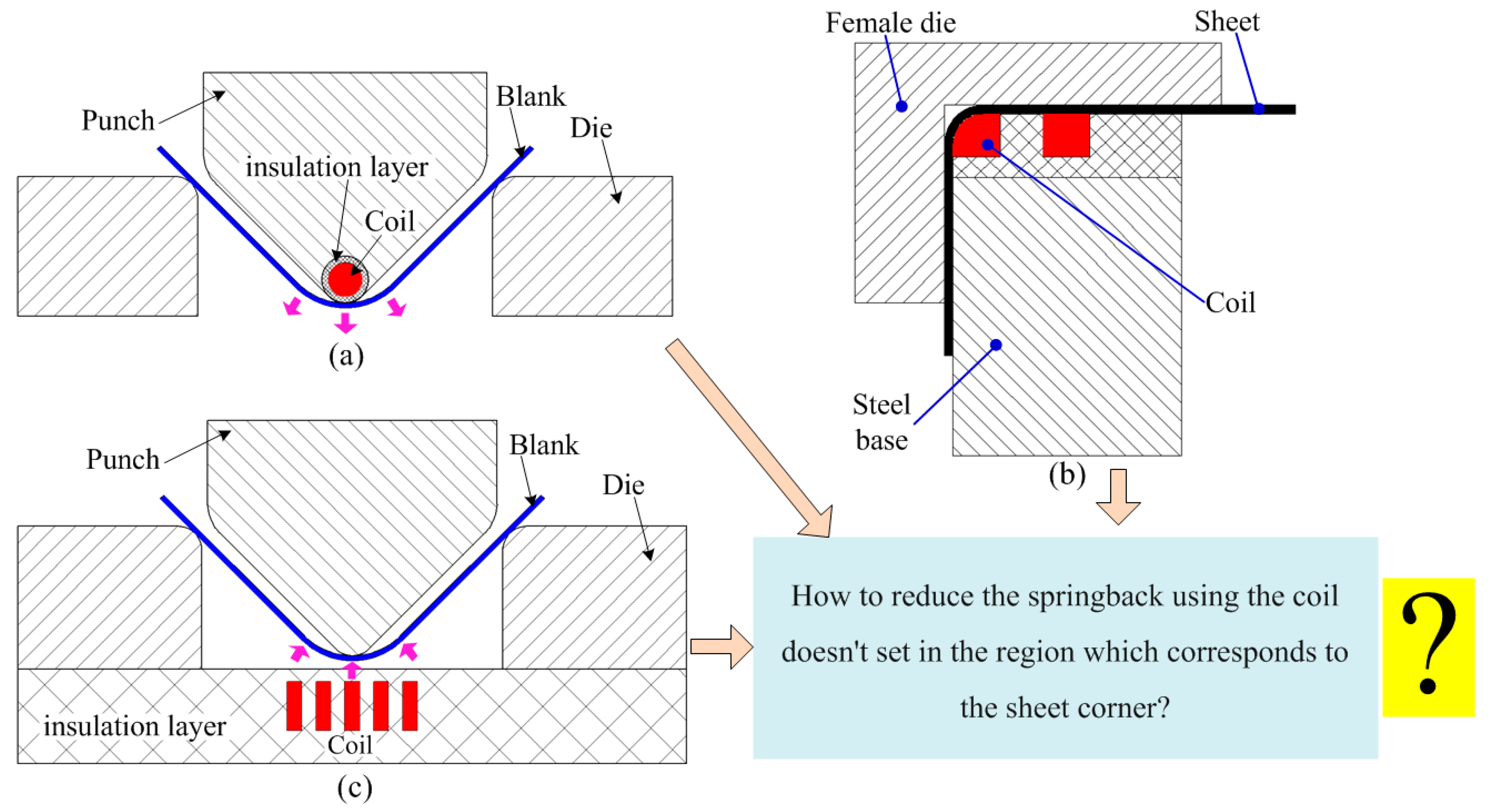
1. Introduction
2. Method and Material
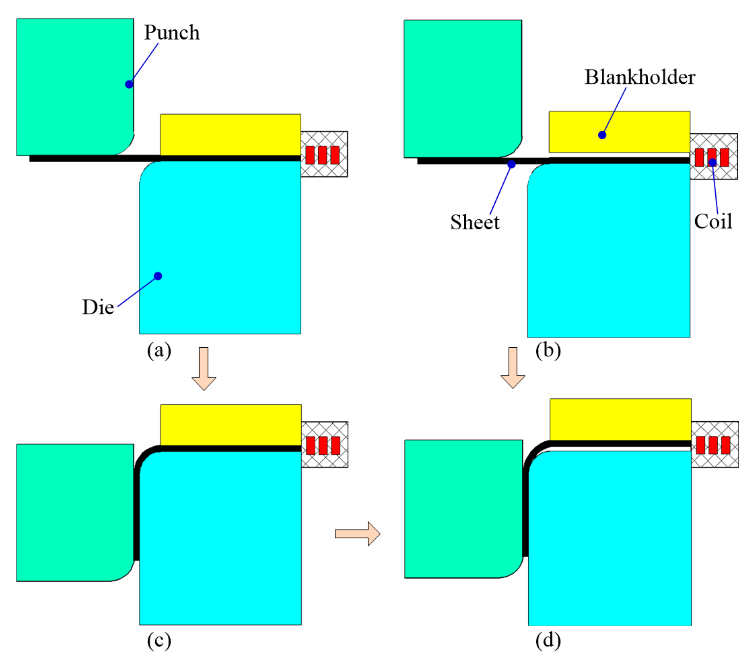
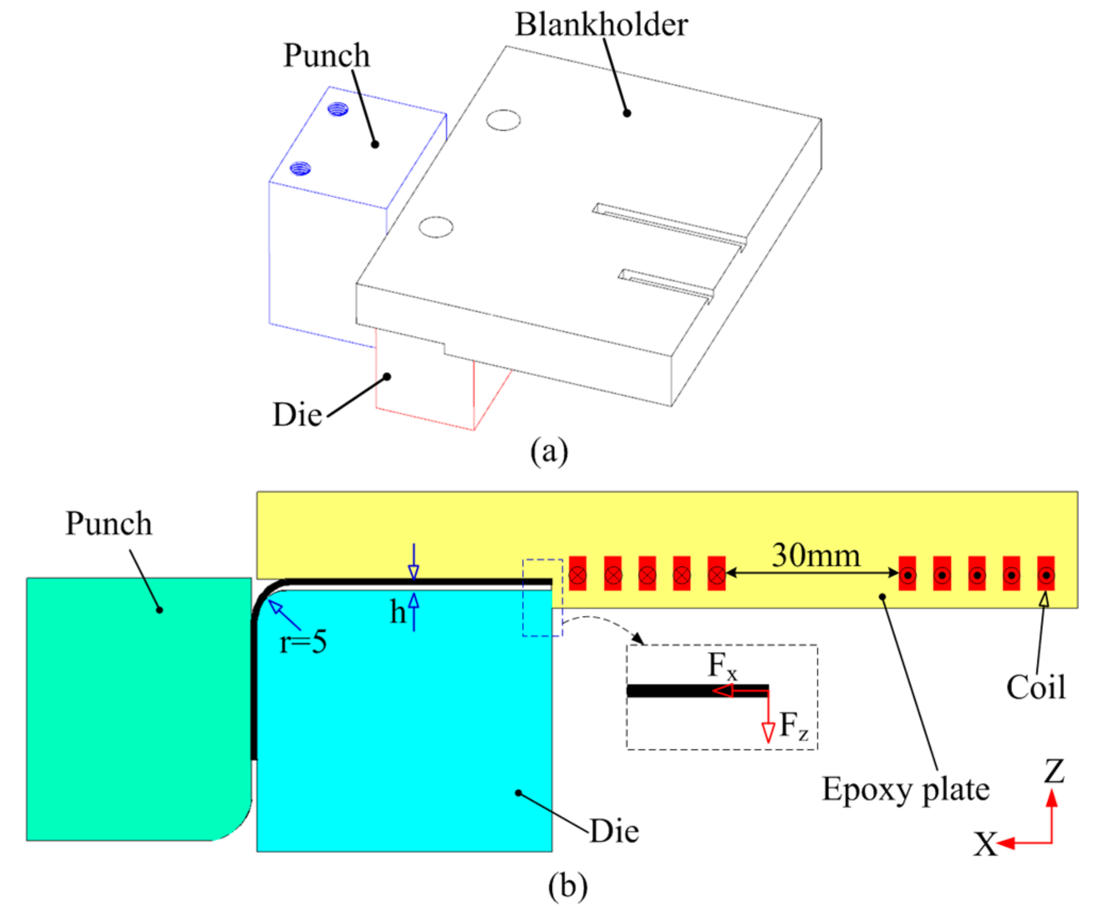
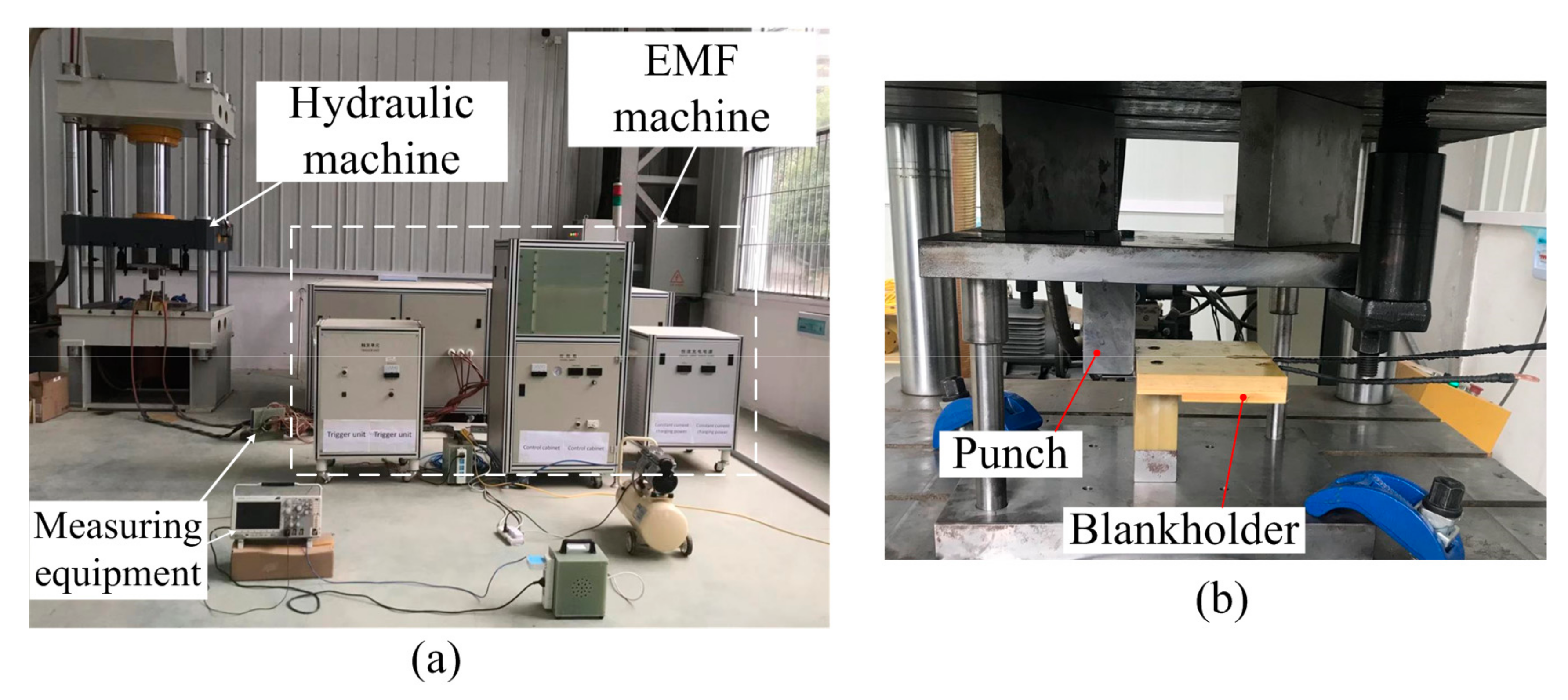
2.1. Forming Method
2.2. Materials and Geometrical Model
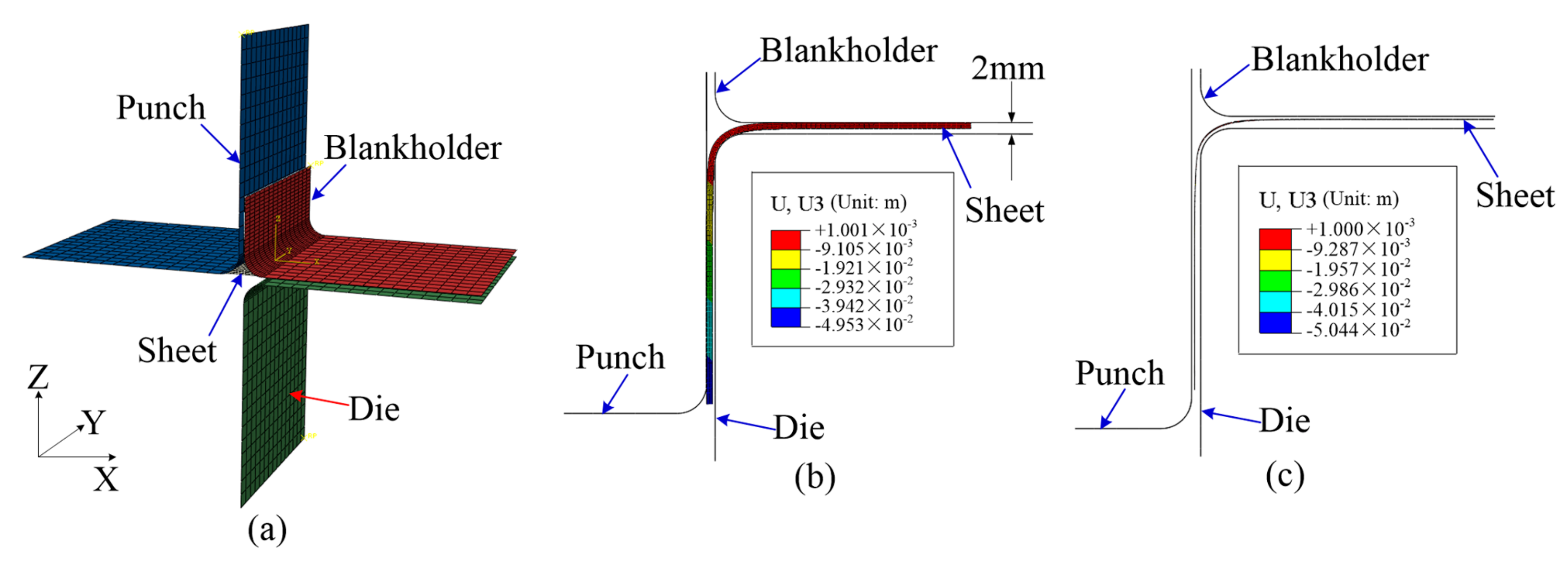
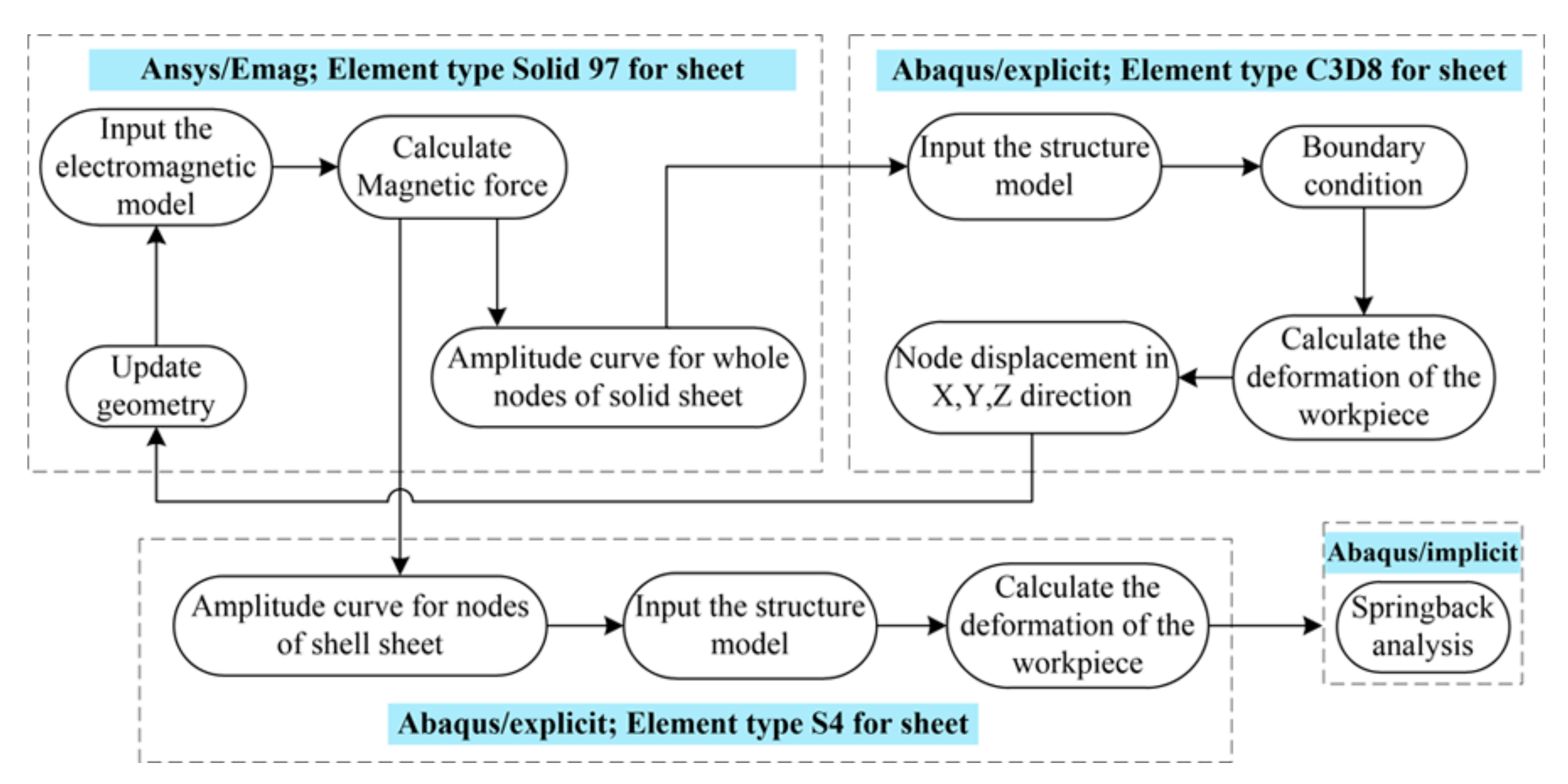
3. Finite Element Modeling
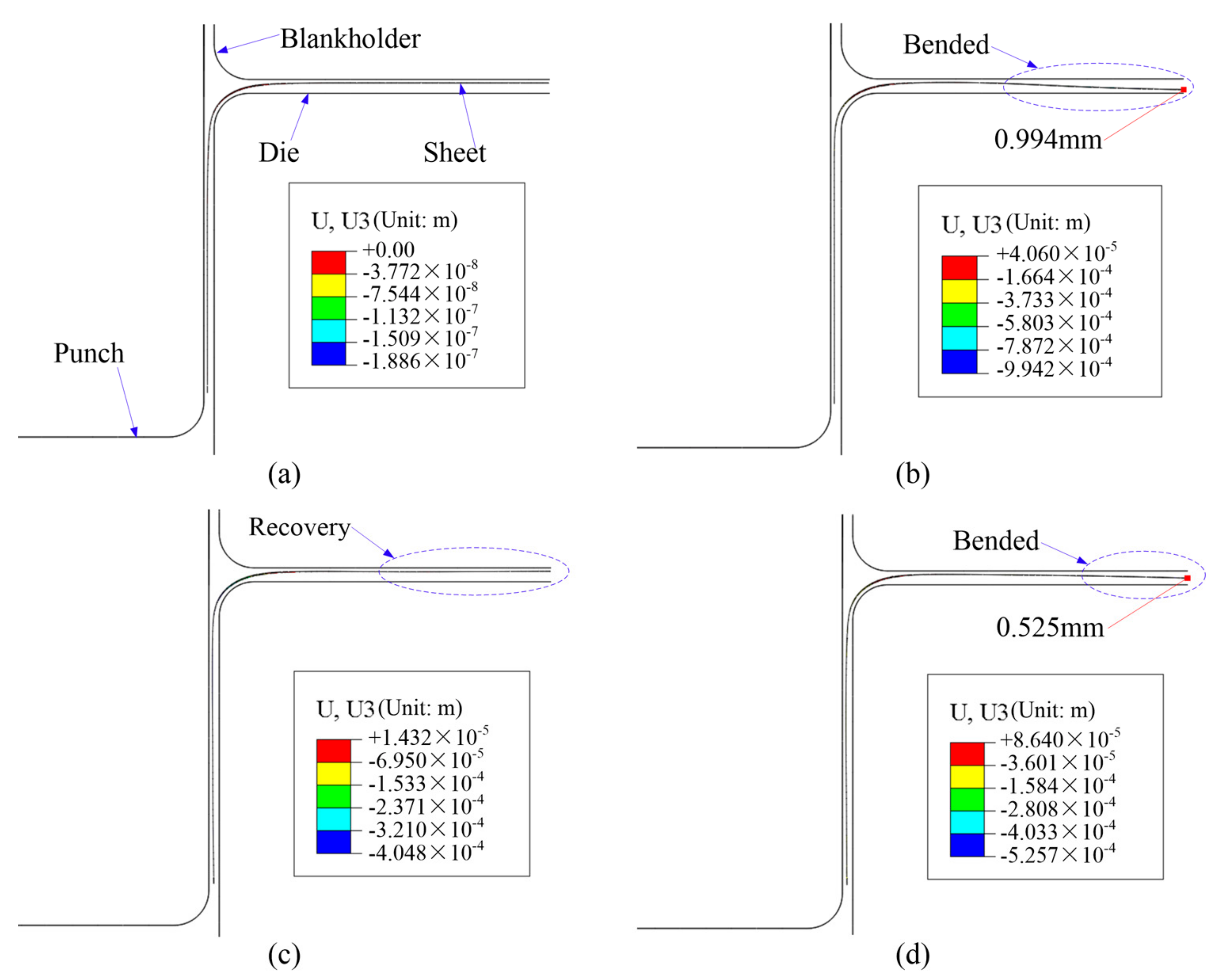
3.1. Quasi-Static Stamping
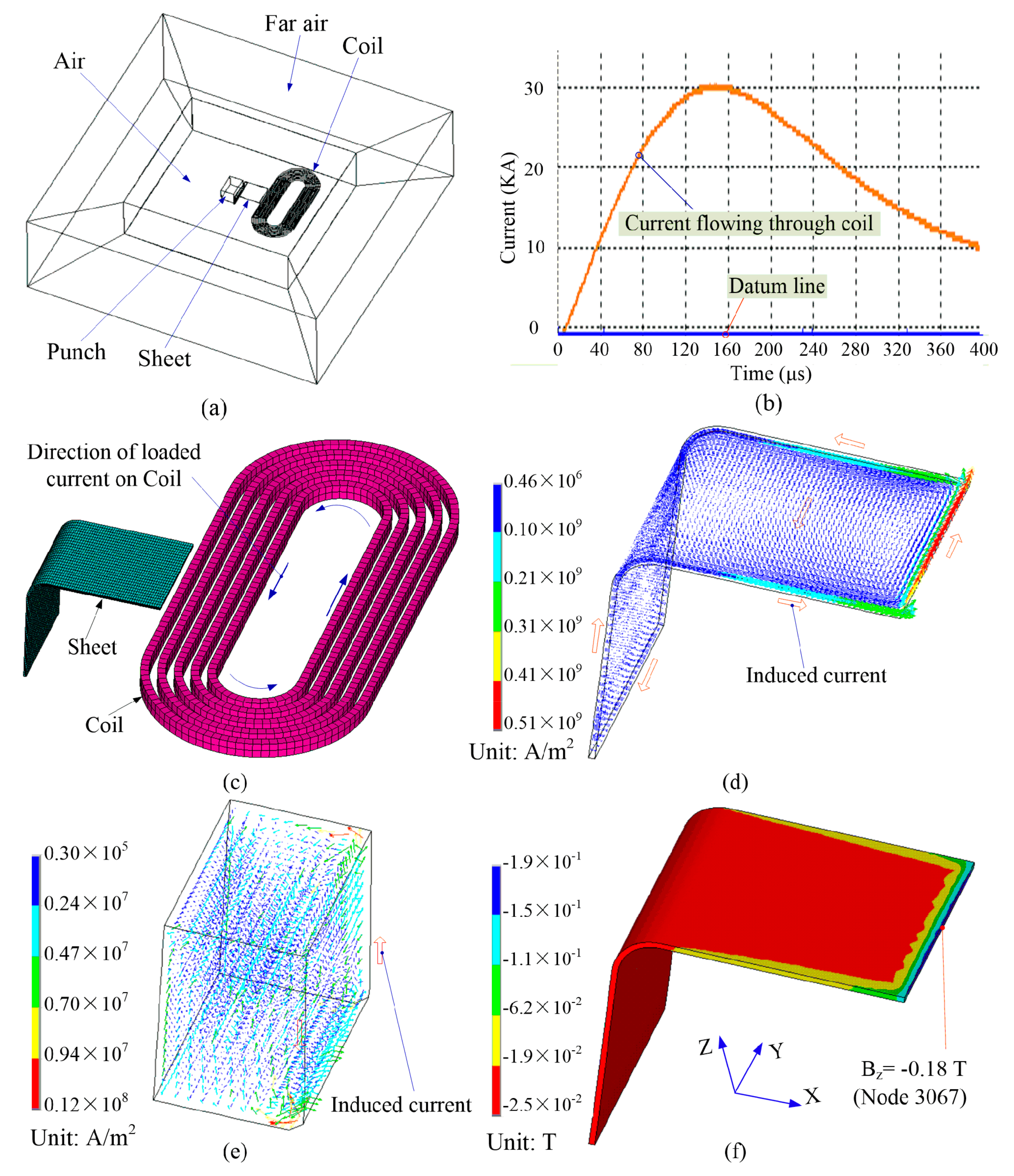
3.2. Electromagnetic Forming Process
4. Effect Factors on Springback Reduction
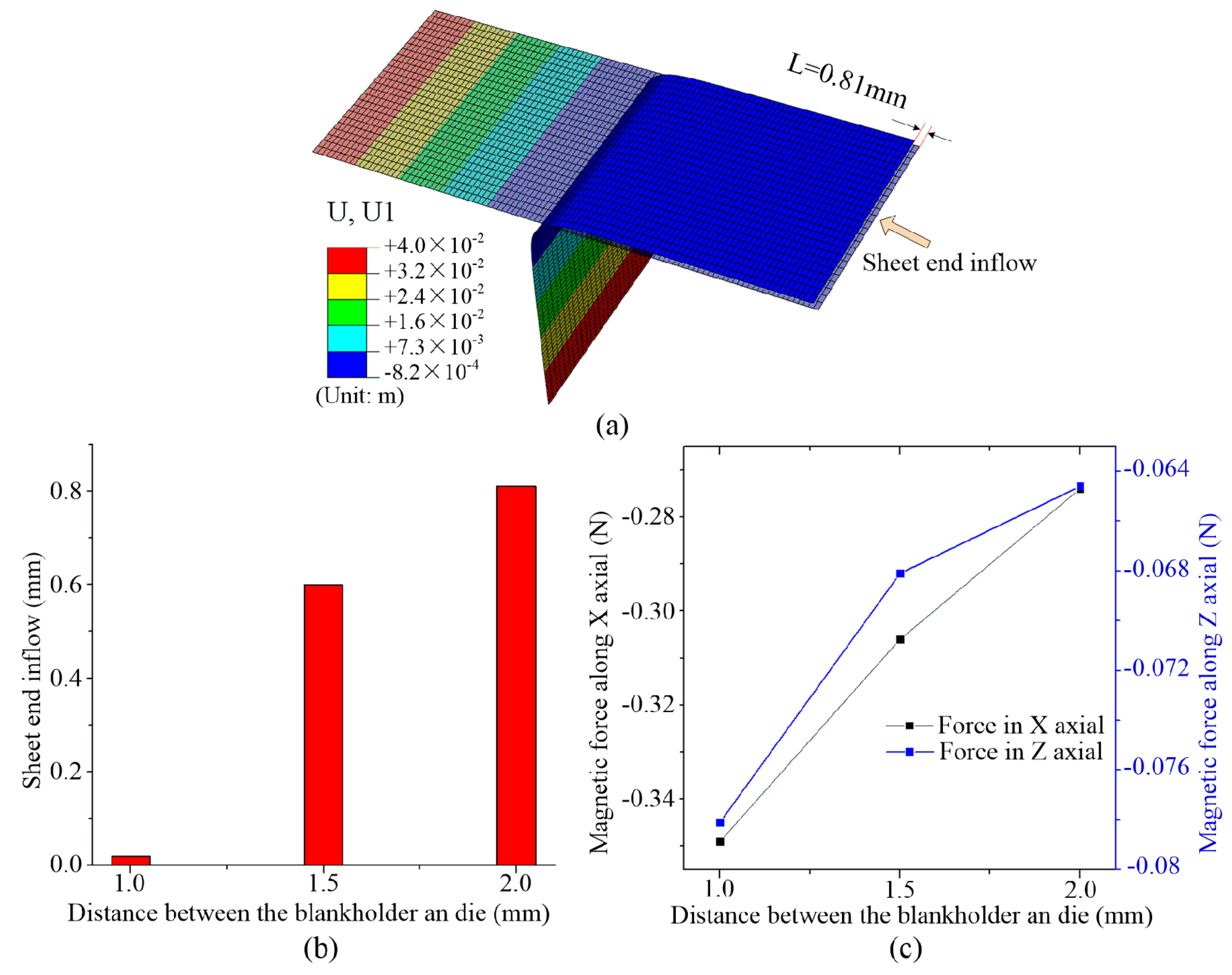
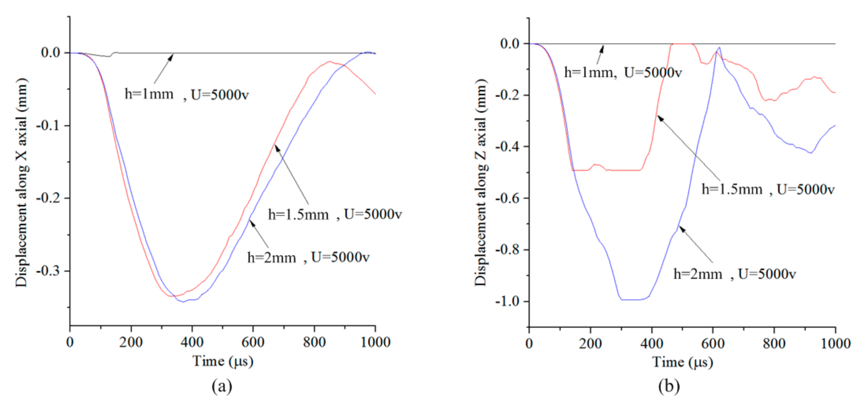
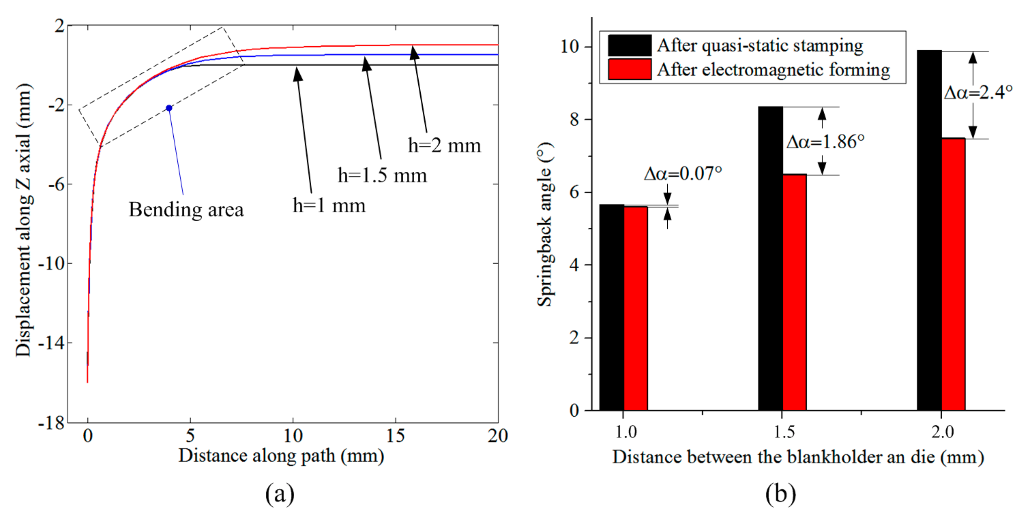
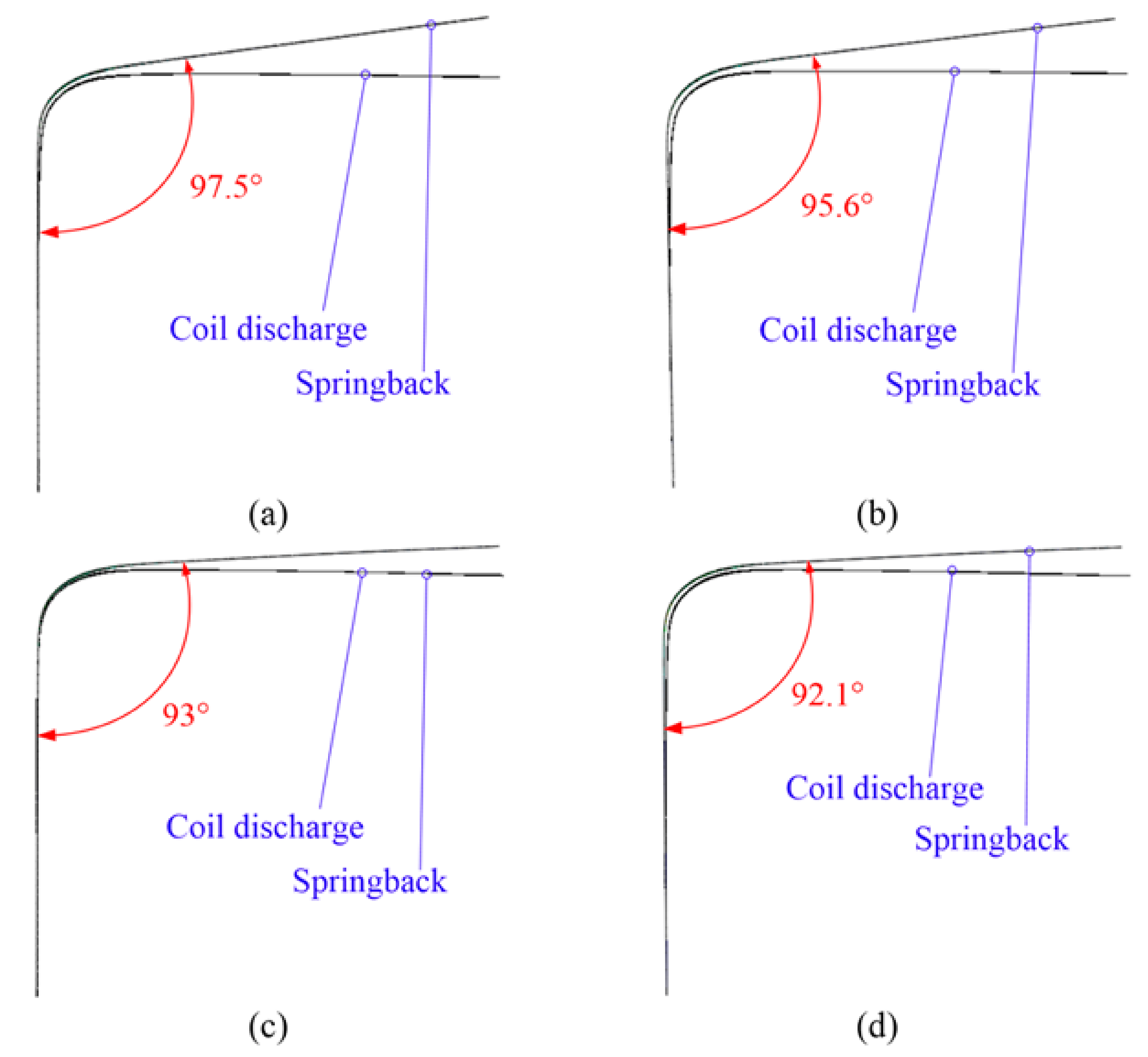
4.1. Distance between the Blank Holder and Die
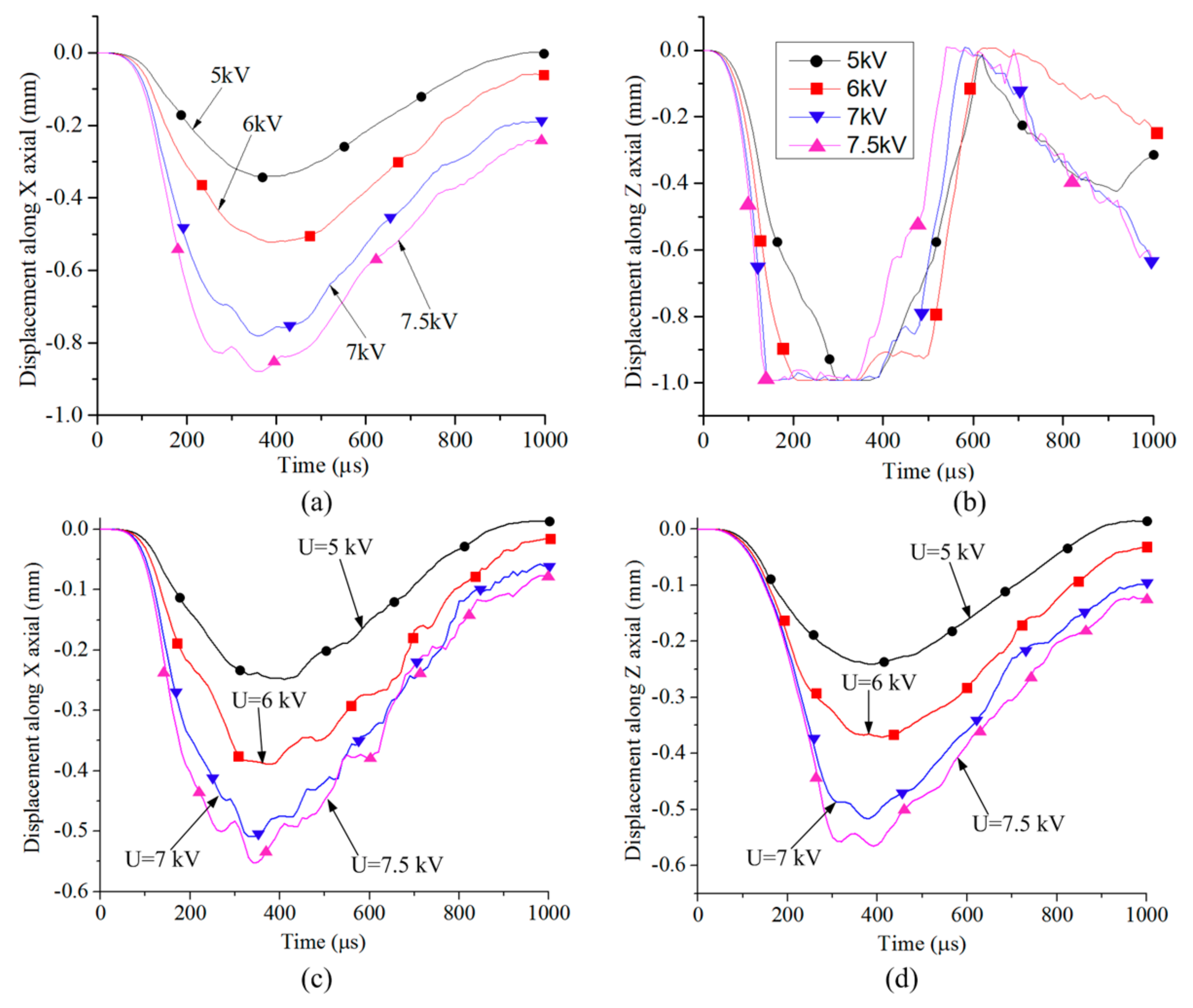
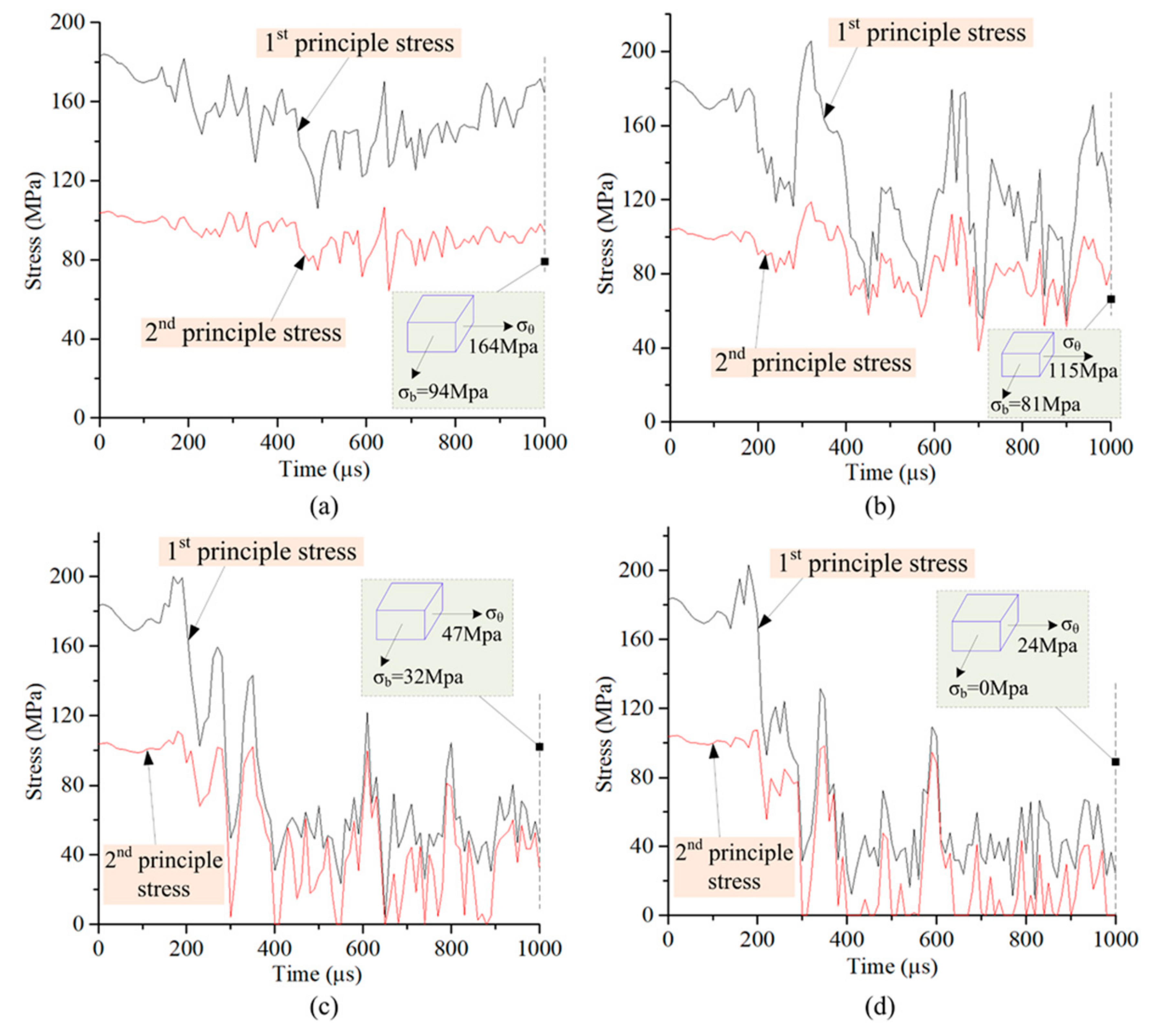
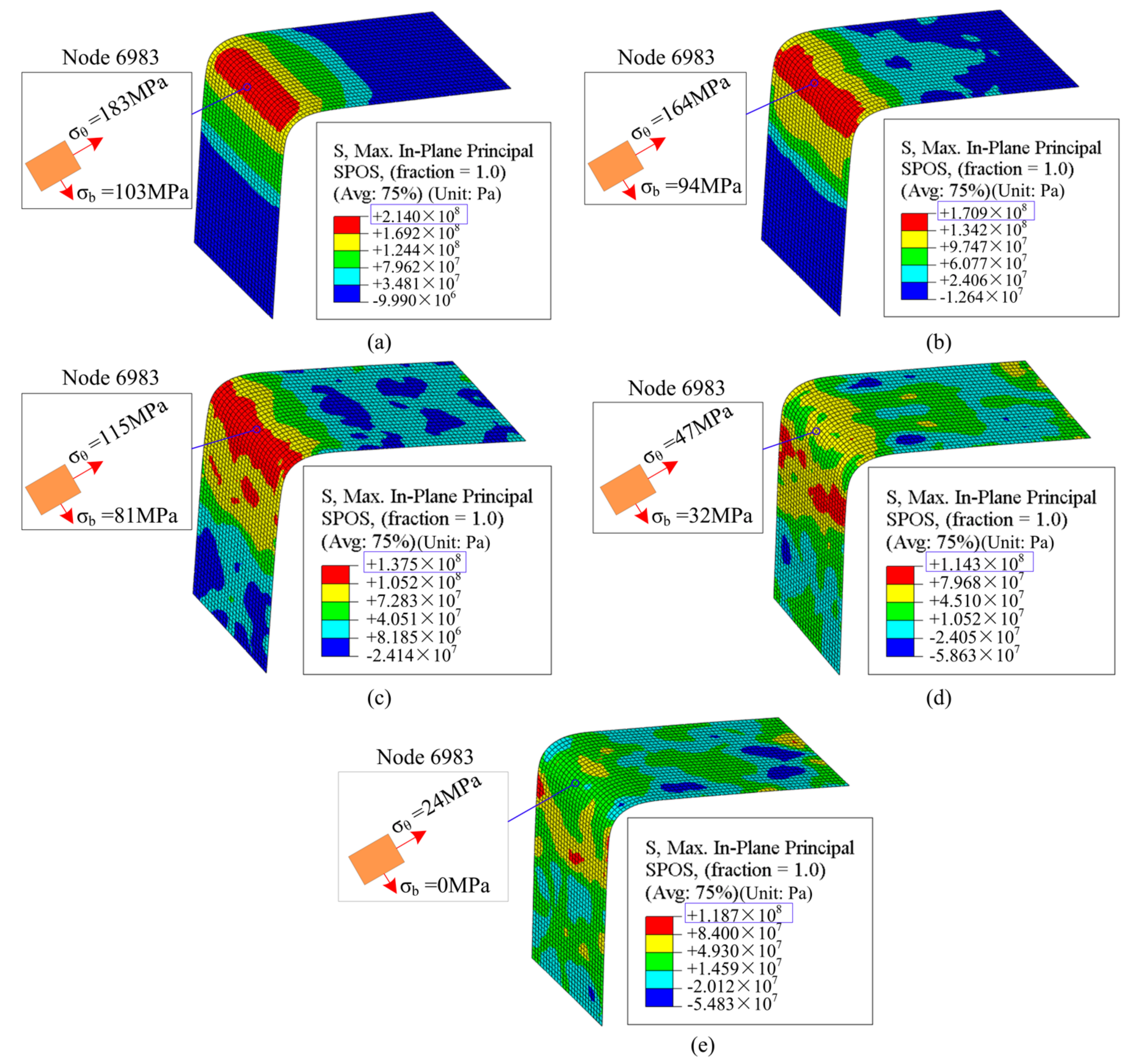
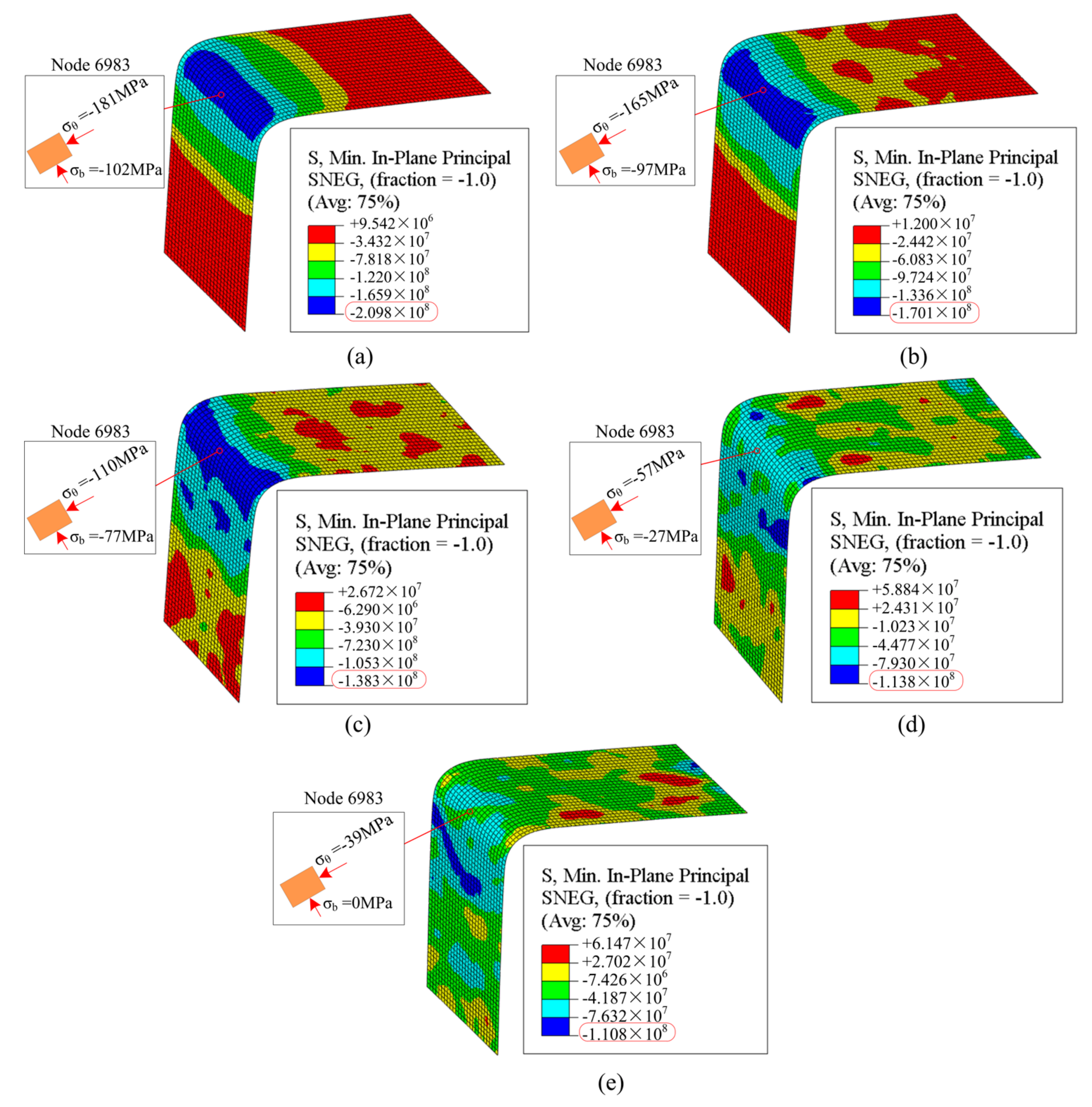
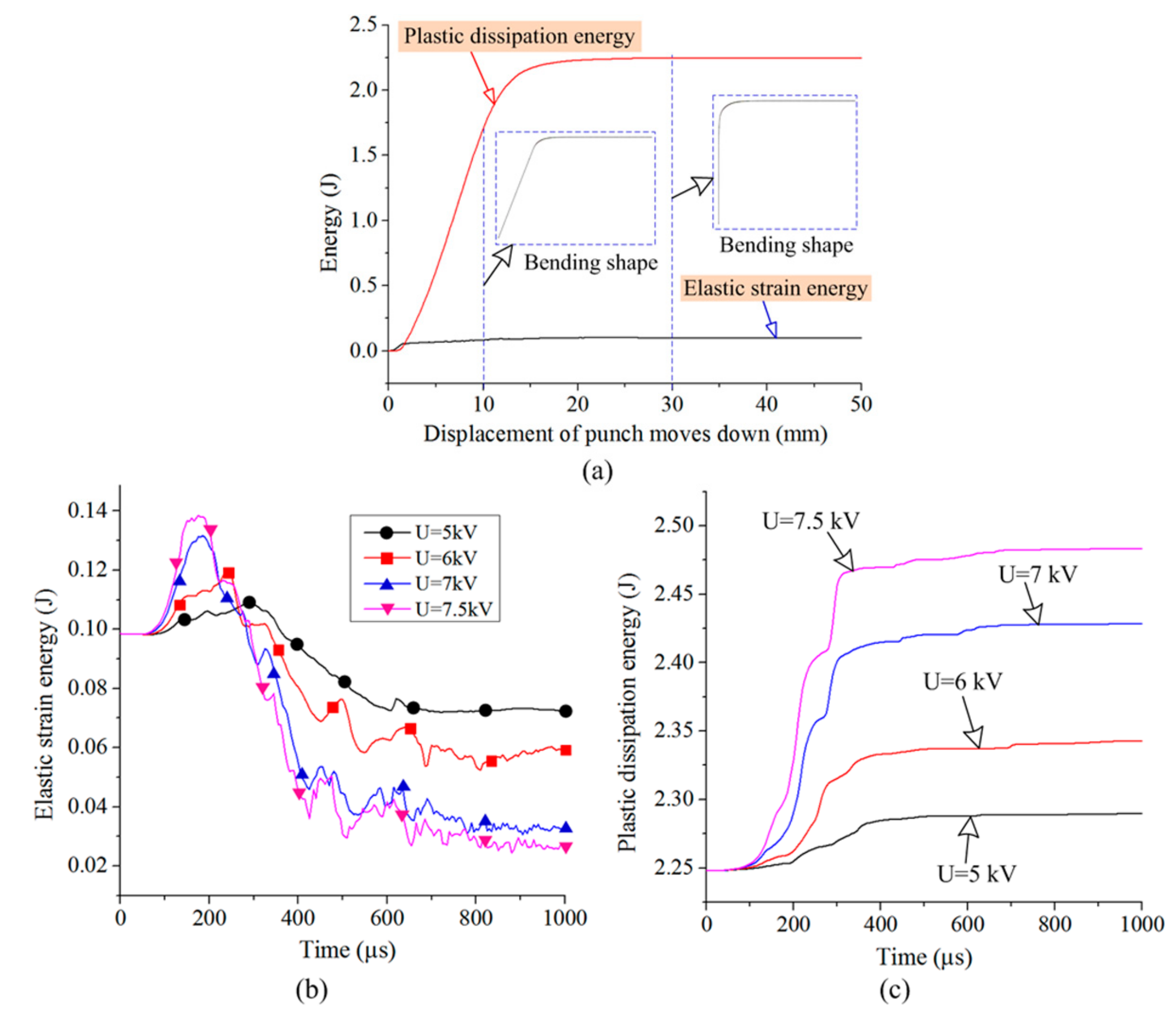
4.2. Discharge Voltage
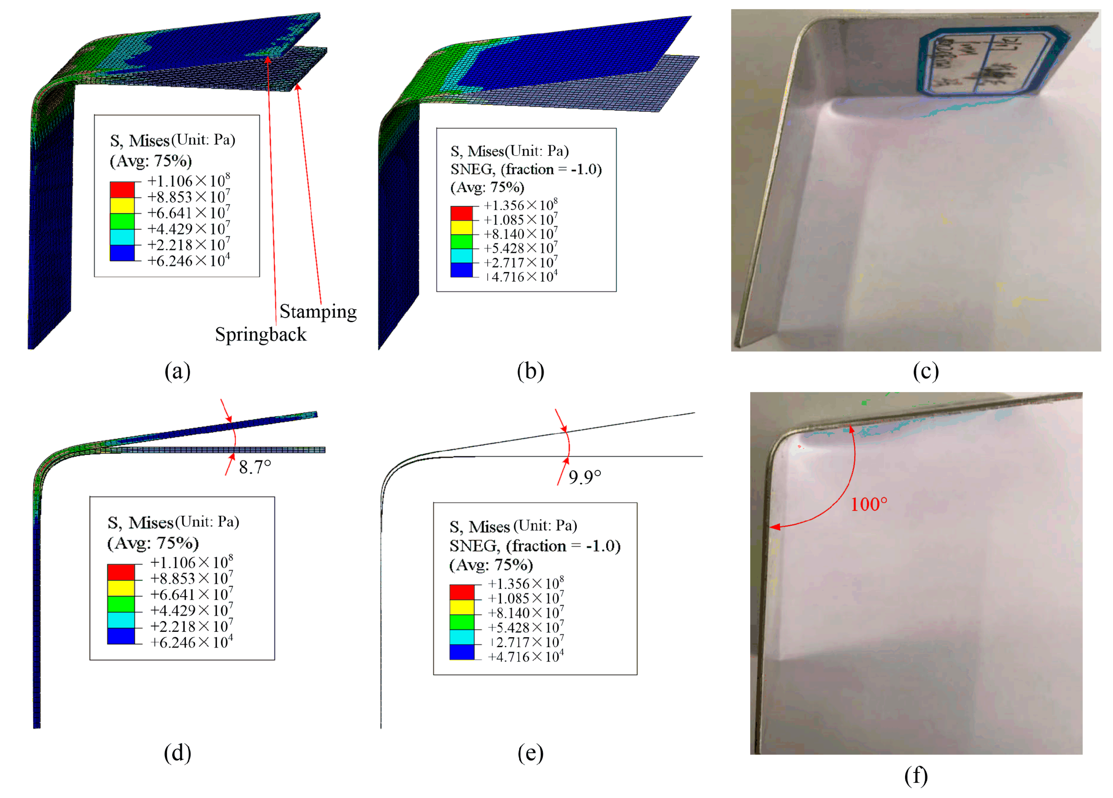
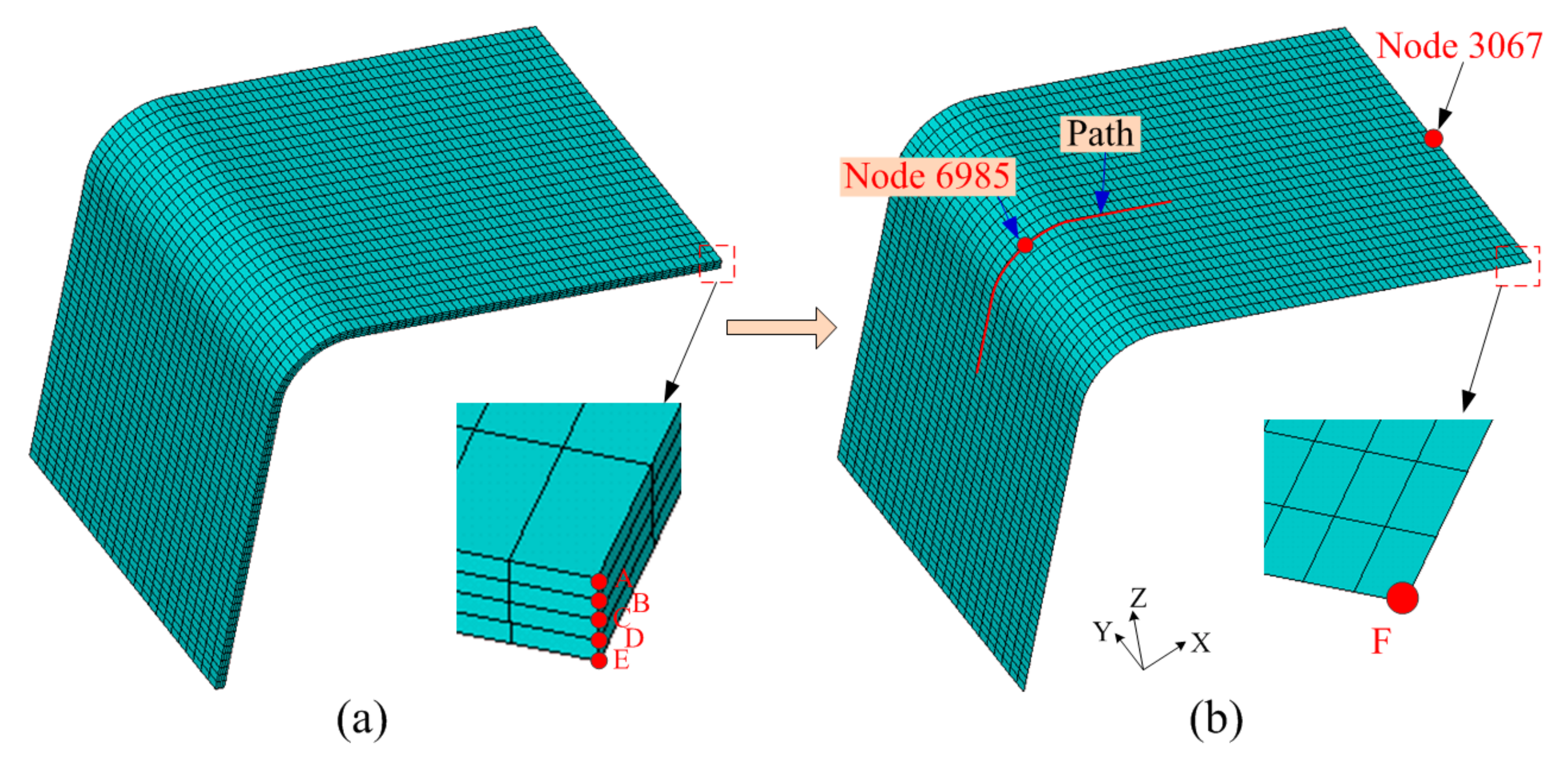
5. Comparison of Experimental and Simulation Results
6. Conclusions
- (1)
- The proposed EMF simulation method is suitable for shell elements, and the simulation results are consistent with experimental results.
- (2)
- Both the tangential stress at the sheet bending region and the elastic strain energy on the sheet decrease with the increasing of discharge voltage. Eventually, as the discharge voltage increases, the springback angle is greatly reduced.
- (3)
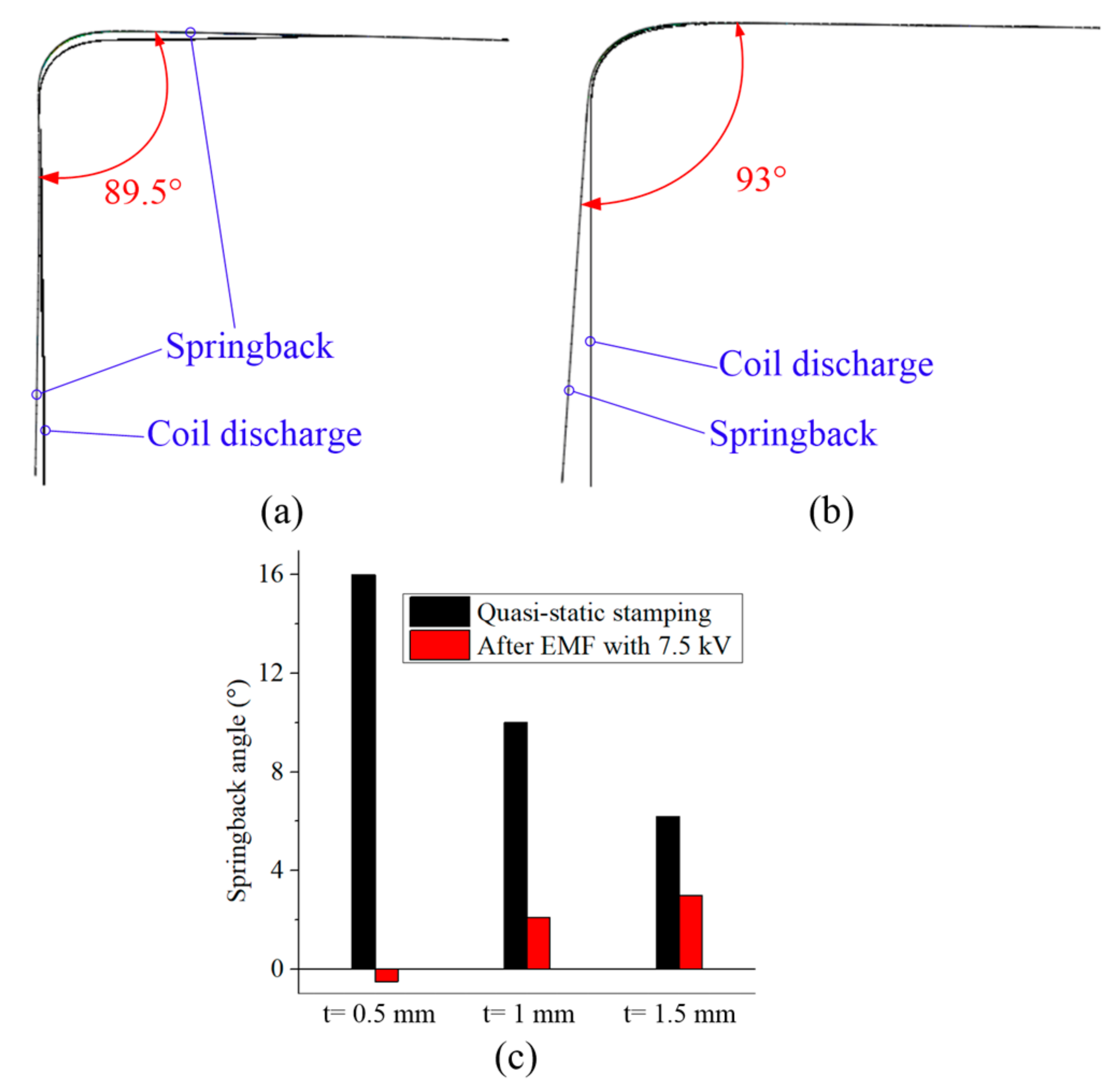
- During the forming process, the gap between the blank holder and the die must be larger than the thickness of the sheet, which helps the sheet undergo certain dynamic movements along the X and Z-axis after the coil discharges. The smaller the sheet thickness, the greater the reduction of the springback angle between the quasi-static stamping and EMF that can be obtained.
Author Contributions
Funding
Conflicts of Interest
References
- Egea, A.J.; Rojas, H.A.; Celentano, D.J.; Travieso-Rodríguez, J.; Fuentes, J.L. Electroplasticity assisted bottom bending process. J. Mater. Process. Technol. 2014, 214, 2261–2267. [Google Scholar] [CrossRef]
- Egea, A.J.; Rojas, H.A.; Celentano, D.J.; Peiró, J.J. Mechanical and metallurgical changes on 308L wires drawn by electropulses. Mater. Des. 2016, 90, 1159–1169. [Google Scholar] [CrossRef]
- Psyk, V.; Risch, D.; Kinsey, B.L.; Tekkaya, A.E.; Kleiner, M. Electromagneticforming—A review. J. Mater. Process. Technol. 2011, 211, 787–829. [Google Scholar] [CrossRef]
- Imbert, J.M.; Winkler, S.L.; Worswick, M.J.; Oliveira, D.A.; Golovashchenko, S. The effect of tool–sheet interaction on damage evolution in electromagnetic forming of aluminum alloy sheet. J. Eng. Mater. Technol. 2005, 127, 145–153. [Google Scholar] [CrossRef]
- Li, F.Q.; Mo, J.H.; Li, J.J.; Zhou, H.Y. Formability of Ti-6Al-4V titanium alloy sheet in magnetic pulse bulging. Mater. Des. 2013, 52, 337–344. [Google Scholar] [CrossRef]
- Seth, M.; Vohnout, V.J.; Daehn, G.S. Formability of steel sheet in high velocity impact. J. Mater. Process. Technol. 2005, 168, 390–400. [Google Scholar] [CrossRef]
- Cui, X.H.; Mo, J.H.; Li, J.J.; Huang, L.; Zhu, Y.; Li, Z.W.; Zhong, K. Effect of second current pulse and different algorithms on simulation accuracy for electromagnetic sheet forming. Int. J. Adv. Manuf. Technol. 2013, 69, 1137–1146. [Google Scholar] [CrossRef]
- Cui, X.H.; Mo, J.H.; Li, J.J.; Xiao, X.T.; Zhou, B.; Fang, J.X. Large-scale sheet deformation process by electromagnetic incremental forming combined with stretch forming. J. Mater. Process. Technol. 2016, 237, 139–154. [Google Scholar] [CrossRef]
- Cui, X.H.; Mo, J.H.; Li, J.J.; Xiao, X.T. Tube bulging process using multidirectional magnetic pressure. Int. J. Adv. Manuf. Technol. 2017, 90, 2075–2083. [Google Scholar] [CrossRef]
- Yu, H.P.; Li, C.F. Effects of current frequency on electromagnetic tube compression. J. Mater. Process Technol. 2009, 209, 1053–1059. [Google Scholar]
- Shang, J.H. Electromagnetically Assisted Sheet Metal Stamping. Ph.D. Thesis, The Ohio State University, Columbus, OH, USA, 2006. [Google Scholar]
- Liu, D.H.; Zhou, W.H.; Li, C.F. Springback control and deformation analysis for electromagnetically assisted bending of U-shaped parts. Chin. J. Nonferrous Met. 2013, 23, 3075–3082. [Google Scholar]
- Sun, C. Deformation Analysis of U Shape Parts Formed by Electromagnetically Assisted Sheet Metal Bending. Master’s Thesis, Harbin Institute of Technology, Harbin, China, 2009. [Google Scholar]
- Iriondo, E.; Gutiérrez, M.A.; González, B.; Alcaraz, J.L.; Daehn, G.S. Electromagnetic impulse calibration of high strength sheet metal structures. J. Mater. Process. Technol. 2011, 211, 909–915. [Google Scholar] [CrossRef]
- Iriondo, E.; Alcaraz, J.L.; Daehn, G.S.; Gutiérrez, M.A.; Jimbert, P. Shape calibration of high strength metal sheets by electromagnetic forming. J. Manuf. Process. 2013, 15, 183–193. [Google Scholar] [CrossRef]
- Woodward, S.; Weddeling, C.; Daehn, G.; Psyk, V.; Carson, B.; Tekkaya, A.E. Agile production of sheet metal aviation components using disposable electromagnetic actuators. In Proceedings of the 4th International Conference on High Speed Forming, Columbus, OH, USA, 9–10 March 2010; pp. 35–46. [Google Scholar]
- Hu, J.H.; Ning, B.W.; Cai, H.; Huang, R.G. Experimental study on springback of aluminum alloy sheet by electromagnetic forming. J. Plast. Eng. 2013, 20, 104–108. [Google Scholar]
- Cui, X.H.; Yu, H.L.; Wang, Q.S. Electromagnetic impulse calibration in V-shaped parts. Int. J. Adv. Manuf. Technol. 2018, 97, 2959–2968. [Google Scholar] [CrossRef]
- Cui, X.H.; Zhang, Z.W.; Yu, H.L.; Xiao, X.T.; Cheng, Y.Q. Springback Calibration of a U-Shaped Electromagnetic Impulse Forming Process. Metals 2019, 9, 603. [Google Scholar] [CrossRef]
- Cui, X.H.; Zhang, Z.W.; Du, Z.H.; Yu, H.L.; Qiu, D.Y.; Cheng, Y.Q. Inverse bending and springback-control using magnetic pulse forming. J. Mater. Process. Technol. 2020, 275, 116374. [Google Scholar] [CrossRef]
- Cui, X.H.; Li, J.J.; Mo, J.H.; Fang, J.X.; Zhou, B.; Xiao, X.T.; Feng, F. Incremental electromagnetic-assisted stamping (IEMAS) with radial magnetic pressure: A novel deep drawing method for forming aluminum alloy sheets. J. Mater. Process. Technol. 2016, 233, 79–88. [Google Scholar] [CrossRef]
- Cui, X.H.; Mo, J.H.; Han, F. 3D Multi-physics field simulation of electromagnetic tube forming. Int. J. Adv. Manuf. Technol. 2012, 59, 521–529. [Google Scholar] [CrossRef]
- Cui, X.H.; Qiu, D.Y.; Jiang, L.N.; Yu, H.L.; Du, Z.H.; Xiao, A. Electromagnetic sheet forming by uniform pressure using flat spiral coil. Materials 2019, 12, 1963. [Google Scholar] [CrossRef]
- Cao, Q.L.; Han, X.T.; Lai, Z.P.; Xiong, Q.; Zhang, X.; Chen, Q.; Xiao, H.X.; Li, L. Analysis and reduction of coil temperature rise in electromagnetic forming. J. Mater. Process. Technol. 2015, 225, 185–194. [Google Scholar] [CrossRef]


© 2020 by the authors. Licensee MDPI, Basel, Switzerland. This article is an open access article distributed under the terms and conditions of the Creative Commons Attribution (CC BY) license (http://creativecommons.org/licenses/by/4.0/).
Share and Cite
Cui, X.; Xiao, A.; Du, Z.; Yan, Z.; Yu, H. Springback Reduction of L-Shaped Part Using Magnetic Pulse Forming. Metals 2020, 10, 390. https://doi.org/10.3390/met10030390
Cui X, Xiao A, Du Z, Yan Z, Yu H. Springback Reduction of L-Shaped Part Using Magnetic Pulse Forming. Metals. 2020; 10(3):390. https://doi.org/10.3390/met10030390
Chicago/Turabian StyleCui, Xiaohui, Ang Xiao, Zhihao Du, Ziqin Yan, and Hailiang Yu. 2020. "Springback Reduction of L-Shaped Part Using Magnetic Pulse Forming" Metals 10, no. 3: 390. https://doi.org/10.3390/met10030390
APA StyleCui, X., Xiao, A., Du, Z., Yan, Z., & Yu, H. (2020). Springback Reduction of L-Shaped Part Using Magnetic Pulse Forming. Metals, 10(3), 390. https://doi.org/10.3390/met10030390