Article

Effect of the Rare Earth Oxide CeO2 on the Microstructure and Properties of the Nano-WC-Reinforced Ni-Based Composite Coating

1
School of Mechanical and Automotive Engineering, Anhui Polytechnic University, Wuhu 241000, China
2
Shanghai Key Laboratory of Materials Laser Processing and Modification, School of Materials Science and Engineering, Shanghai Jiao Tong University, Shanghai 200240, China
3
Research Center for Molecular Materials, University of Oulu, P. O. Box 3000, FIN-90014 Oulu, Finland
4
School of Computer and Information, Anhui Polytechnic University, Wuhu 241000, China
*
Authors to whom correspondence should be addressed.
Metals 2020, 10(3), 383; https://doi.org/10.3390/met10030383
Submission received: 4 February 2020 / Revised: 8 March 2020 / Accepted: 12 March 2020 / Published: 17 March 2020

Abstract

:
In this study, the addition of the rare earth oxide CeO2 was investigated to alter the microstructural properties of the nano-WC-reinforced Ni-based composite coatings. The reinforced composite was prepared on the 42CrMo steel surface using a semiconductor laser. The morphology and microstructure of coatings were analyzed using a scanning electron microscope (SEM), energy dispersive spectroscopy (EDS), and X-ray diffraction (XRD). Further, the digital microhardness tester and high-temperature friction and wear tester were used to observe the mechanical properties. The results indicated that the addition of CeO2 eliminated the cracks from the surface of the coatings and effectively reduced the number of pores. The phases were mainly observed as γ-Ni(Fe) in a solid solution, and some residual WC and W2C phases were observed. In addition, Fe3C, Cr23C6, M6C (M = W, Fe, and Ni), SiC and Cr7C3 composite carbides, Si2W and NiW tungsten compounds, and CeFe2- and CeNi2-containing Ce complex compounds were formed on the coating. The rare earth oxide CeO2 composite-modified coating mainly comprised dendrites, crystal cells, strips, and massive microstructures. The reinforced phases of the modified coating presented uniform dispersion distribution with the addition of 1% CeO2, and the structures were significantly refined. The maximum microhardness of the modified coating was approximately 1560 HV0.2, which was approximately 20% higher than that of the unmodified composite coating. The minimum wear loss of the modified coating was 6.1 mg and the minimum frictional coefficient was approximately 0.23, which were better than those of the unmodified coating. The wear mechanism of the nano-WC-reinforced Ni-based coating was primarily adhesive, whereas that of the CeO2 composite modified coating was mainly abrasive particle wear, which accompanied adhesive wear.

1. Introduction

42CrMo steel is a structural steel exhibiting a unique combination of high strength, good hardenability, toughness, and low tempering brittleness. This steel is often used to manufacture important mechanical parts having a high comprehensive evaluation index with respect to strength, lasticity, and toughness, including springs, rolling rolls, oil drill pipe joints, cutter bodies, and large gears [1,2,3]. Currently, many machines have to operate in extreme environments, causing regular early failure of major components. For example, the likelihood of crack expansion or even peeling under a small external force is high when the 42CrMo steel parts are slightly damaged or cracked. Therefore, fatigue failure can be easily induced once the cutter body is driven into the coal mining roadways [4]. As a new kind of surface modification technology, laser cladding uses a high-energy laser beam to simultaneously melt the cladding material and substrate surface. Subsequently, the molten material rapidly cools to form metallurgical bonds between the cladding material and the substrate. Using this technology, the surface of the 42CrMo steel could be provided additional mechanical properties, including increased hardness, wear resistance, and erosion wear resistance.
The addition of WC to many composite materials results in the generation of good chemical catalytic properties, thermal properties, optical properties, surface effects, small size effects, and other properties [5,6]. For instance, nano-WC is often used as an enhancement phase within the metal matrix composites, which has attracted considerable research attention [7,8]. Tang Kangkang et al. reported that the addition of nano-WC resulted in a considerable amount of uniform coatings, which were harder and less abrasive than the traditional large-particle WC-reinforced Ni-based coatings [9,10]. Benea L et al. studied the WC-reinforced Ni-based coatings by laser cladding, proving that the addition of nano-WC can refine grains, improve the coating quality, and enhance the hardness and friction resistance of the coating considerably [11,12].
Rare earth elements can segregate impurities from grain boundaries, which alters the structure of the composite coating by inhibiting the growth of the crystals, improving the hardness and wear resistance of the substrate surface. The addition of rare earth elements can effectively increase the wettability and fluidity of the molten pool materials, reducing the porosity of the molten pool and smoothing the surface of the coating. Therefore, the application of rare earth particles to modify the protective coatings has become a popular topic in the field of surface modification [7,13,14,15]. Zhu Kaihuan et al. modified the metal alloy coatings using rare earth oxides La2O3 and Nd2O3 and proved that modified rare earth coatings contained significantly less cracks, causing the structure to become quite refined and dense. The microhardness could also be increased 2–3 times with improved oxidation resistance [16,17]. The effects of Y2O3 and La2O3 on the properties of the Ni-based cladding coatings were reported by Meiyan Li et al. [18,19], and similar results were obtained with the addition of certain amounts of rare earth oxides, including a refined structure, coating uniformity, increased microhardness, and wear resistance, as well as improved fracture toughness.
Until now, many researchers have investigated modified Ni-based coatings using rare earth or reinforced Ni-based coatings with nano-WC and obtained good results. However, to the best of our knowledge, systematic studies on nano-WC-reinforced Ni-based coatings with rare earth CeO2 addition have not been reported to date. In this study, varied amounts of the rare earth oxide CeO2 were used to modify the Ni-based coating on the surface of the 42CrMo steel using the laser cladding technology. The characteristic changes in microstructure, phase composition, microhardness, and wear resistance were explored as a function of the CeO2 content.

2. Experimental Materials and Methods

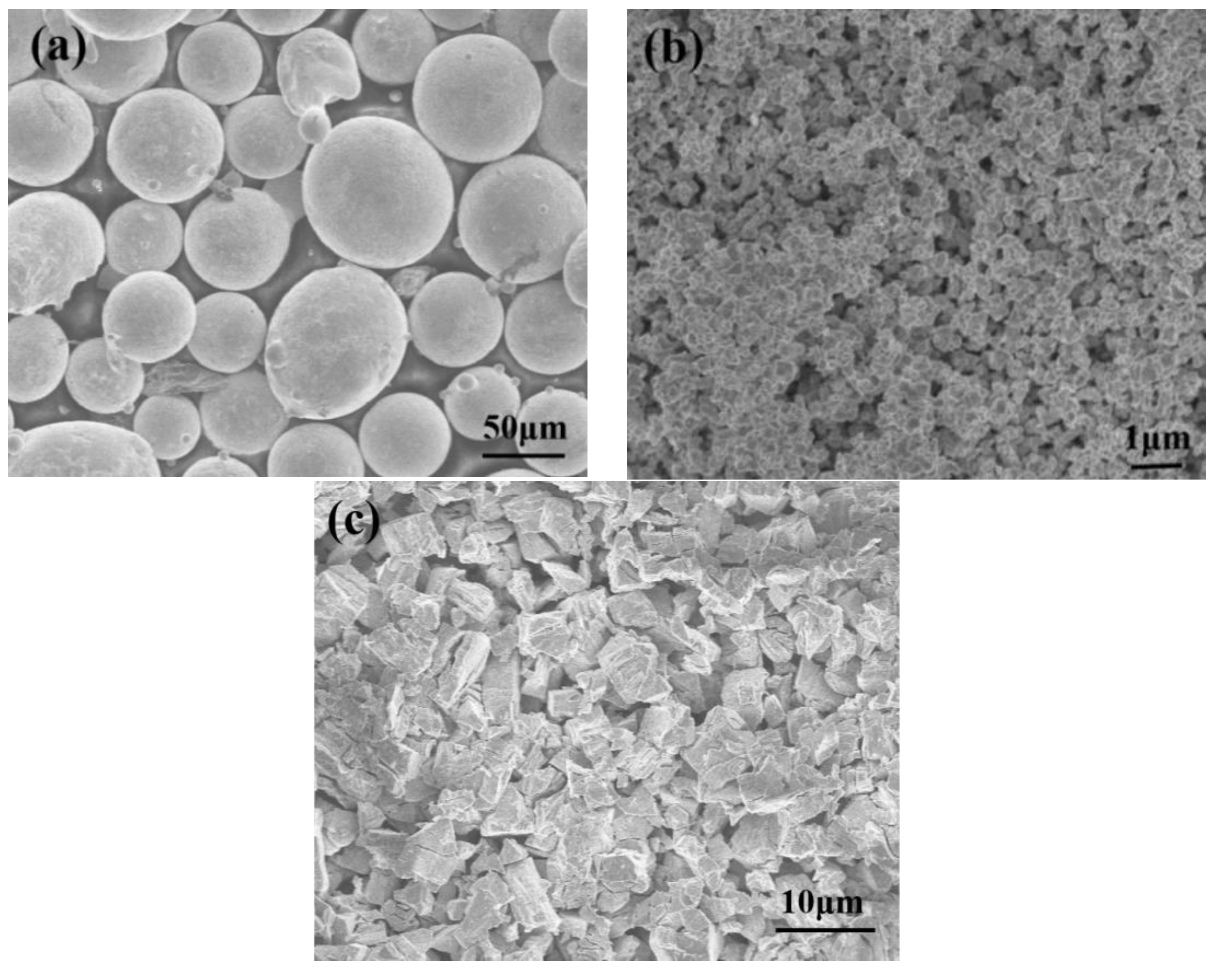
2.1. Experimental Materials

The 42CrMo steel was selected as the substrate, which was cut to dimensions of 20 mm × 70 mm × 15 mm. Its chemical composition is presented in Table 1. The cladding powder is a mixture of the Ni60 alloy powder, nano-WC particles, and rare earth oxide CeO2. The Ni60 alloy powders are approximately 44–104 μm in size. The chemical composition of Ni60 is presented in Table 2. The nano-WC powders have an average particle size diameter of 0.4 μm and a purity of greater than 99.9%. The CeO2 powders have sizes of 5–10 μm and a purity of 99.5%. The powder morphology analyzed by a scanning electron microscope (SEM) is shown in Figure 1a–c.

2.2. Experimental Methods

The surface of the 42CrMo steel was polished and washed using ethanol, and was subsequently blow dried for further usage. A mixture powder of Ni60 and nano-WC with a weight ratio of 7:3 was prepared, and 0%, 0.5%, 1.0%, 1.5%, and 2.0% CeO2 powders were added to this mixture (Table 3). The as-prepared five mixed powders were completely homogenized using a QM-3SP2 ball mill for 2 h. Finally, the obtained mixed powders were uniformly placed onto the 42CrMo steel substrate using a binder with a thickness of 2 mm and dried in a vacuum oven at 100°C for 2 h.
A 3500 W semiconductor laser (DL-035Q, Rofin, Germany) was applied to the laser cladding. Optimized process parameters were adopted in this experiment. The laser power was set to 1800 W with a scanning speed of 2.0 mm/s and a focal length of 15 mm. The width of each laser beam was set to 5 mm with an overlap rate of 45%. Argon gas was used with a flow rate of 10 L/min to prevent the alloy from being burned off or oxidizing. In addition, the substrate was preheated to 300 °C before cladding to reduce the occurrence of cracks.
The metallographic microstructure of the coatings was observed using a metallographic microscope. An S-4800 SEM (Hitachi, Tokyo, Japan) coupled with an EDS was used to analyze the microstructure and elemental composition of the samples. The phase identification of the coatings was performed using X-ray diffraction (XRD, Bruker AXS, Karlsruhe, Germany) with the Cu Kα radiation at 40 kV and 40 mA. The existence of phases was determined by detecting whether the peak phase angle coincided with the phase of the PDF card. The microhardness of the cladding layer was verified using a HVS 1000 B digital hardness instrument (Huayin, Shandong, China) under a load of 200 g for 15 s. A microhardness average value of 3 points was reported in this study. An HT-1000 high-temperature friction and wear tester (Zhongke Kaihua, Lanzhou, China) was used to verify the friction and wear performance of the coatings. Here, a GR (4Cr3Mo3W4VNb) steel ball with a diameter of 6 mm was used as the anti-wear material. The detailed experimental parameter is presented in Table 4. The sample was weighed before and after the tests to confirm the loss of friction and wear; also, it was automatically measured to record the frictional coefficient using a computer-linked sensor. The three-dimensional (3D) morphology of the surface after each test was observed using PS50 3D non-contact morphometry (Nanovea, California, USA).

3. Results and Discussion

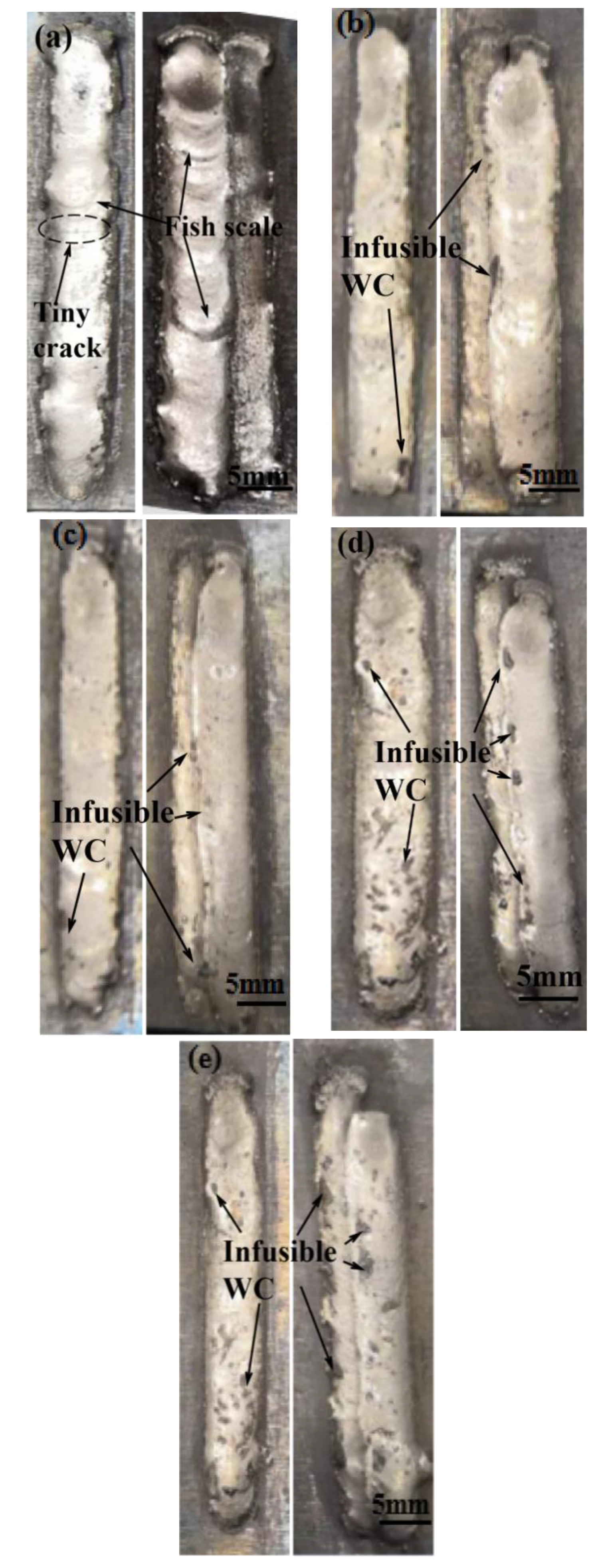
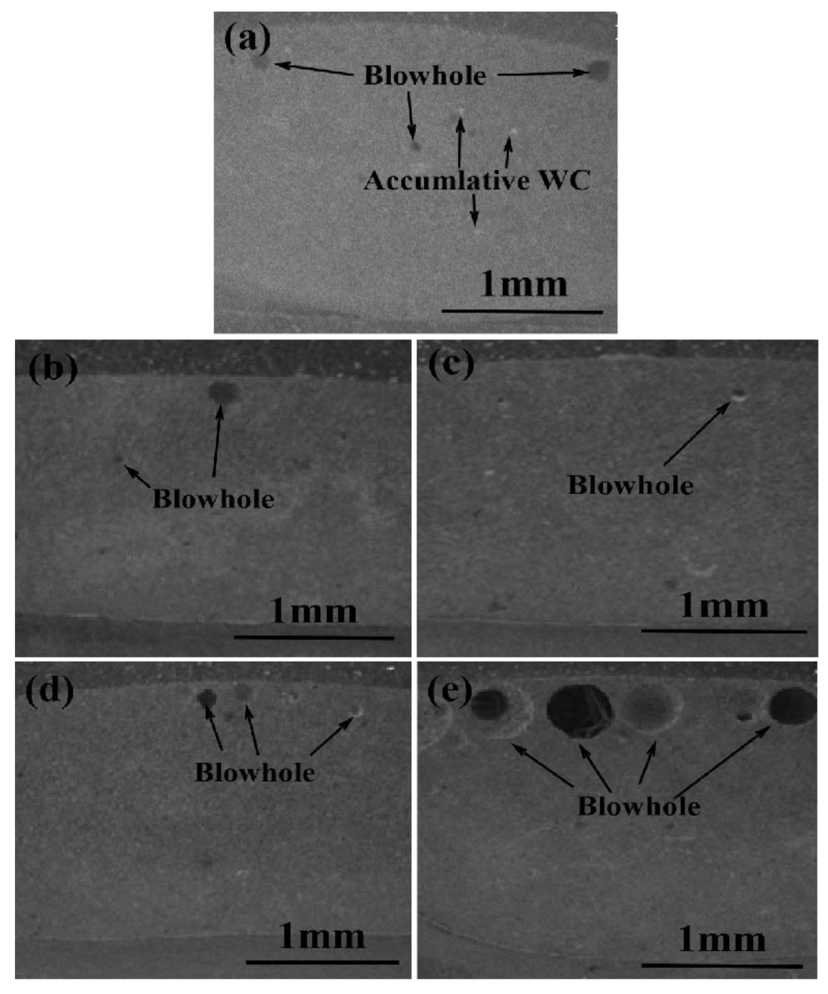
3.1. Morphological Analysis of the Coatings

Figure 2 denotes the surface morphology of the single and lap-modified composite coatings with different CeO2 contents. Microcracks are generated on the surface of the unmodified coating (without CeO2), and some areas are raised to obtain a scale-like feature. Conversely, the modified composite coating containing CeO2 is evidently crack-free and relatively flat. However, refractory WC residues are formed on the surface of the modified coatings, which increase with increasing amount of CeO2. This can be attributed to the improved energy absorption capacity of rare earth elements to effectively enhance the wettability and fluidity of the cladding materials, making the surface of the cladding layer smoother. Further, the purification ability of the rare earth elements repels some refractory WC to the surface.
Figure 3 shows the cross-sectional morphology of five single coatings with different CeO2 contents under identical processing parameters. The resulting average thickness of the coatings is approximately 2.0–2.3 mm. The cross sections also present different morphologies, and some obvious porosity can be observed in each case. During the laser cladding process, the CO and CO2 gases are generated by the reaction of WC and CeO2 [20], as shown in Equation (1).
2WC+CeO2 → W2C + CO + CeO (W2C + CO2 + Ce)
WC reacts with CeO2 at high temperatures to generate CO and CO2 gases. These gases form pores in the coating because they cannot escape under the extremely fast cooling rate of the molten pool [21]. Figure 3a presents the enhanced cladding layer that is obtained without adding CeO2. The binding between the coating and the substrate is good. There are no obvious holes or bubbles at the bottom of the coating. However, pores form in the middle of the coating, albeit small in size. The pores within the upper part of the coating are more prominent and relatively larger and are likely to be caused by the tendency of the bubbles to escape upward during the laser cladding process. Further, a few tiny white dots are observed to aggregate. According to the energy spectrum analysis, these white spots mainly comprise C and W atoms, which are the unmelted nano-WC particles. The modified composite cladding layer containing 0.5% CeO2 is shown in Figure 3b. Large pores are generated within the coating, particularly in the upper parts, whereas little to no porosity can be observed in the middle or lower parts of the coating. With the addition of 1.0% CeO2, a drastically different morphology can be observed, showing only a few tiny pores in Figure 3c. This is likely due to the increased presence of the rare earth oxide CeO2, which improves the wettability and fluidity of the cladding material and refines the coating structure, efficiently reducing the porosity [14,18]. However, the pores increase with the continued addition of CeO2, as shown in Figure 3d,e. The number of pores and size both reach maxima when the CeO2 content is 2.0%. The further addition of CeO2 not only increased the number of pores significantly but also increased the size and shape. This is probably due to the addition of the rare earth oxide CeO2 that increased the presence of oxygen inside the coating and increased the amount of generated CO and CO2 gases. When the gas cannot escape from the molten pool, the pores expand within the coating. The pores can cause the structure looseness in the coating, which decreases the strength of the coatings. In addition, pores are an important factor that causes stress concentration, resulting in the cracking of the coating. Therefore, adding an appropriate amount of the rare earth oxide CeO2 to reduce the generation of pores can effectively enhance the quality and improve the mechanical properties of the coating. Regardless, no cracks are observed within the cross-sectional areas of all the coatings with different CeO2 contents.

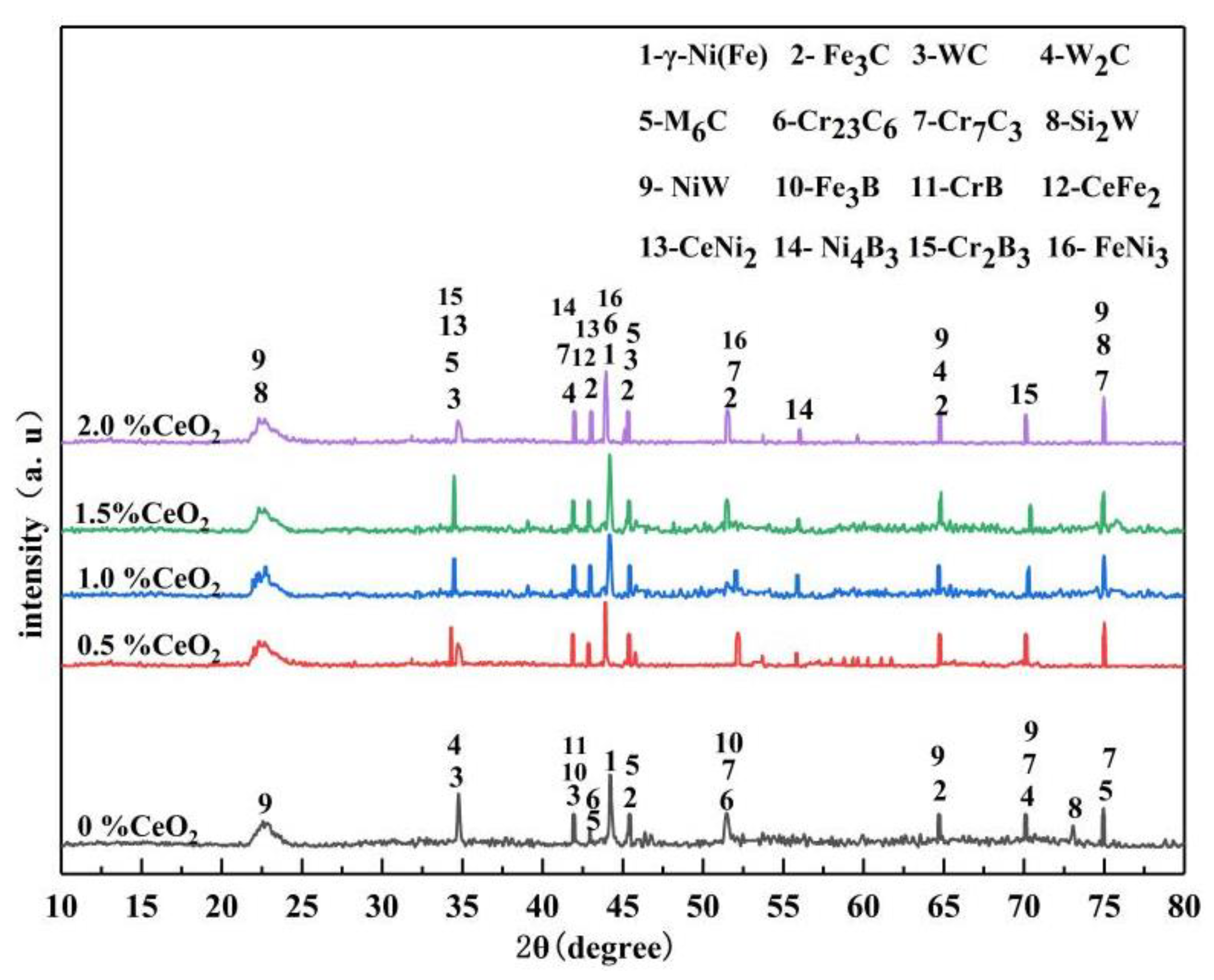
3.2. Phase Analysis of the Coatings

The XRD patterns of the coatings before and after the addition of the rare earth oxide CeO2 are shown in Figure 4. The main diffraction peaks of the coatings is γ-Ni (Fe), indicating that the γ-Ni (Fe) is the matrix phase. This can be attributed to the cladding process parameters with a low scanning speed, an increase in the molten pool energy per unit time, an increase in the melt time, strengthened convection, a considerably uniform melt composition, and an increase in diffusion. FeNi3 and Cr23C6 phases are detected from the main peak of the coating incorporated with CeO2. WC and W2C phases are also present, as indicated in the XRD patterns of the two coatings, suggesting that the coatings with WC particles remained, whereas some of the WC particles were converted into W2C during laser processing. The XRD patterns show that a complex chemical reaction occurs between the WC nanoparticles and Ni60 during the cladding process, resulting in the generation of a series of complex compounds, including Fe3C, Cr23C6, M6C (M = W, Fe, and Ni), SiC, Cr7C3 composite carbides, CrB, Fe3B and Si2W, and NiW. However, when compared with the nano-WC-reinforced coating, only CrB and Fe3B are absent. However, two new borides, namely, Ni4B3 and Cr2B3, can be observed in the modified coatings. Further, the presence of CeFe2 and CeNi2 can be attributed to the addition of CeO2.

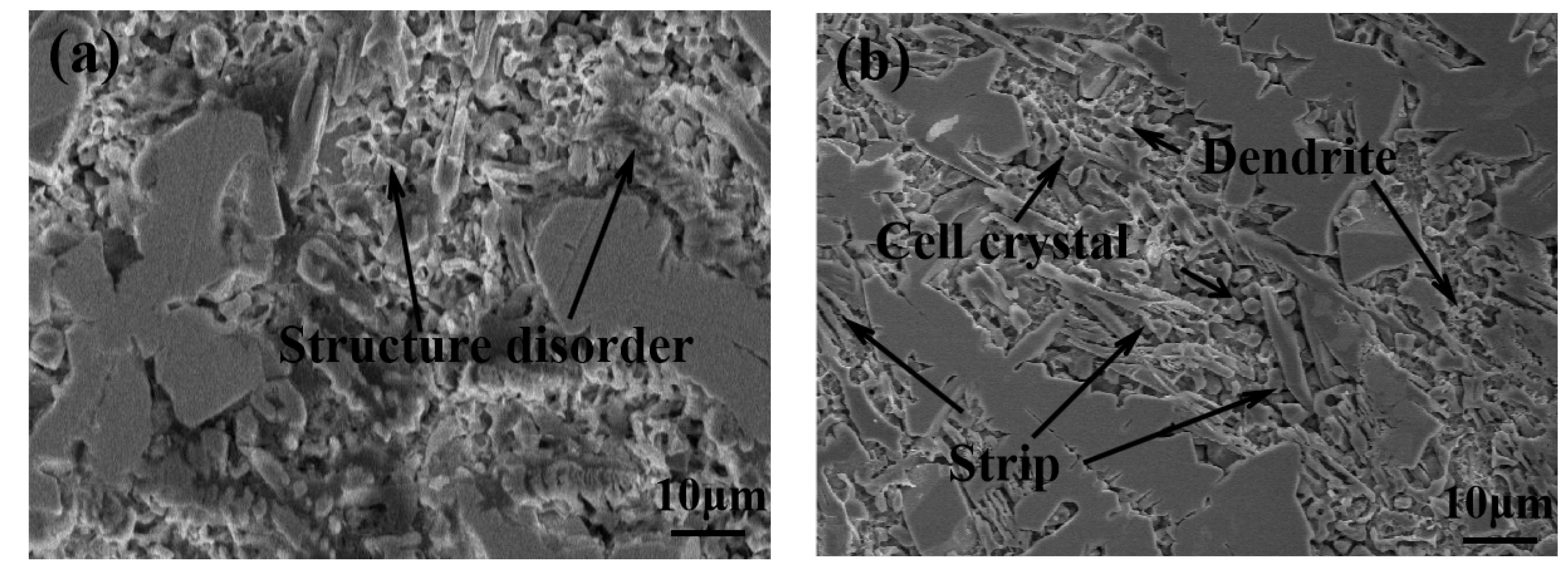
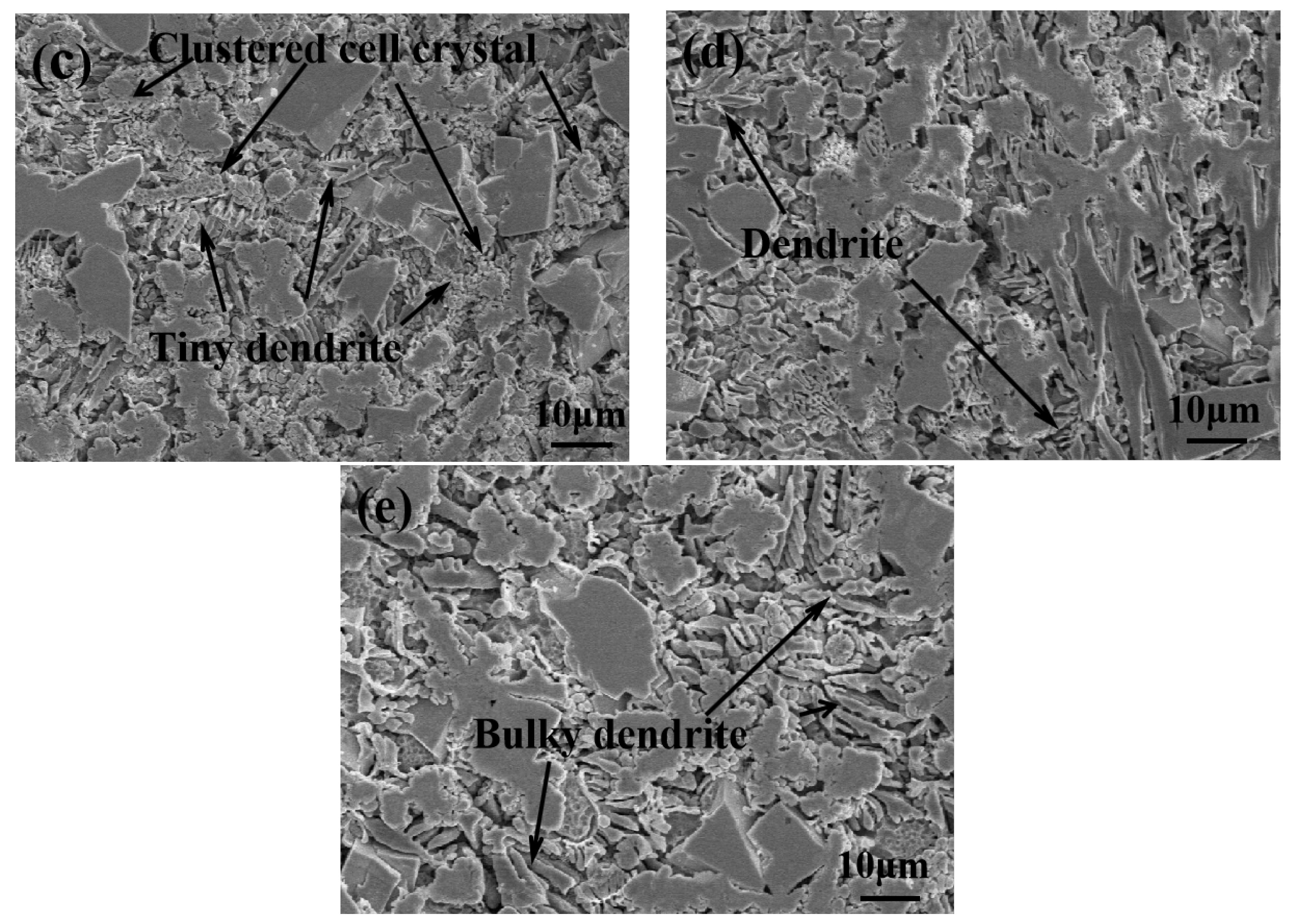
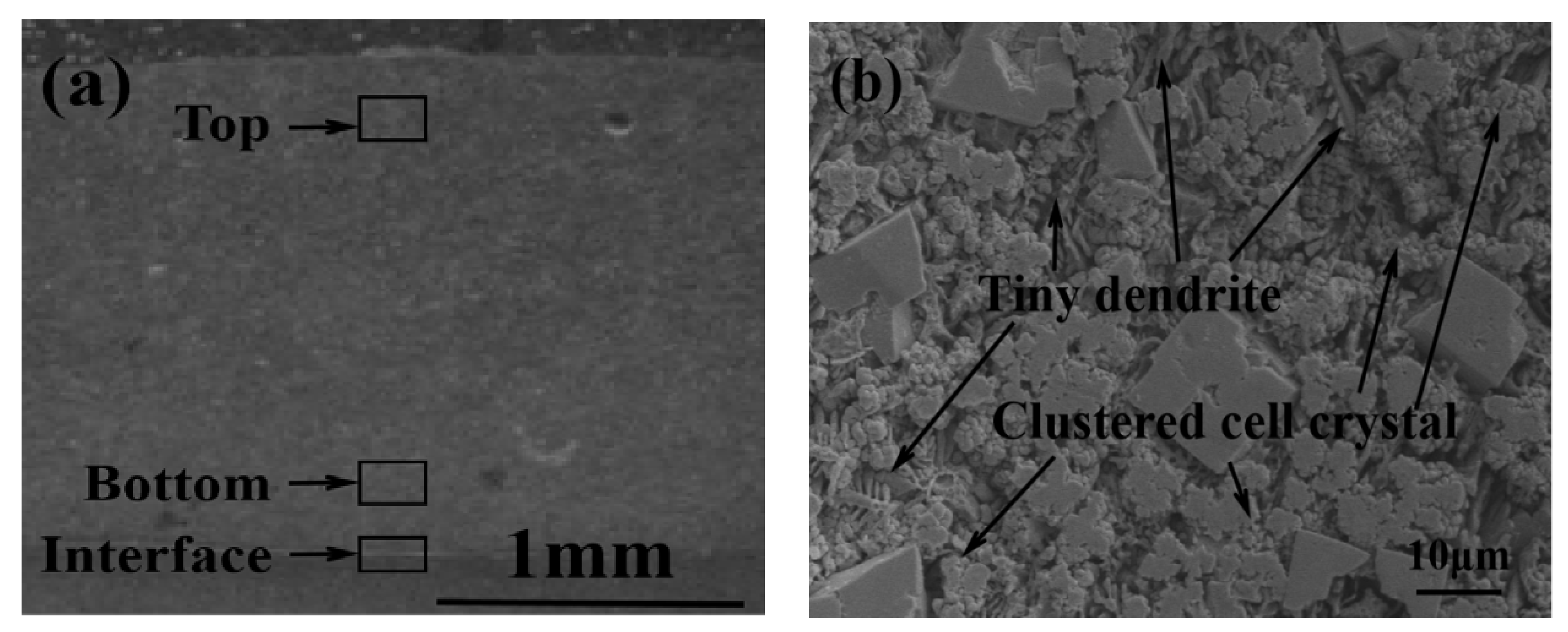
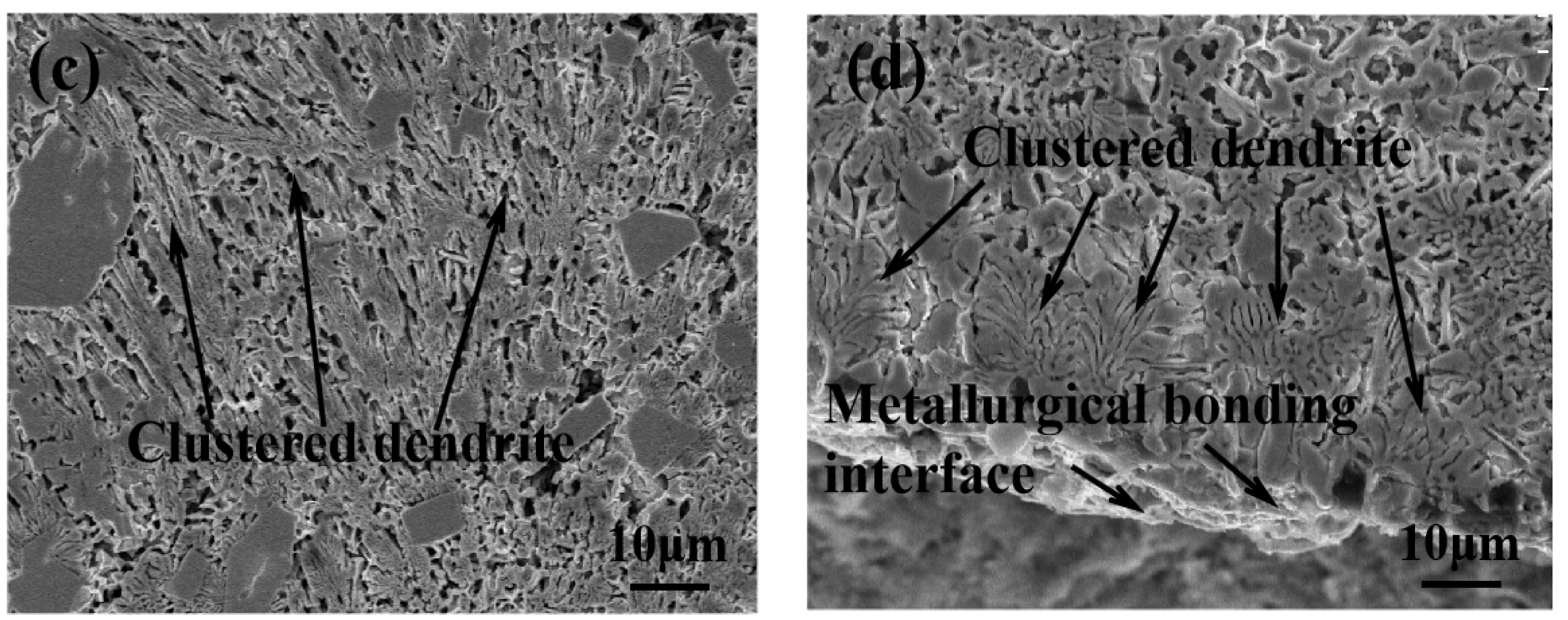
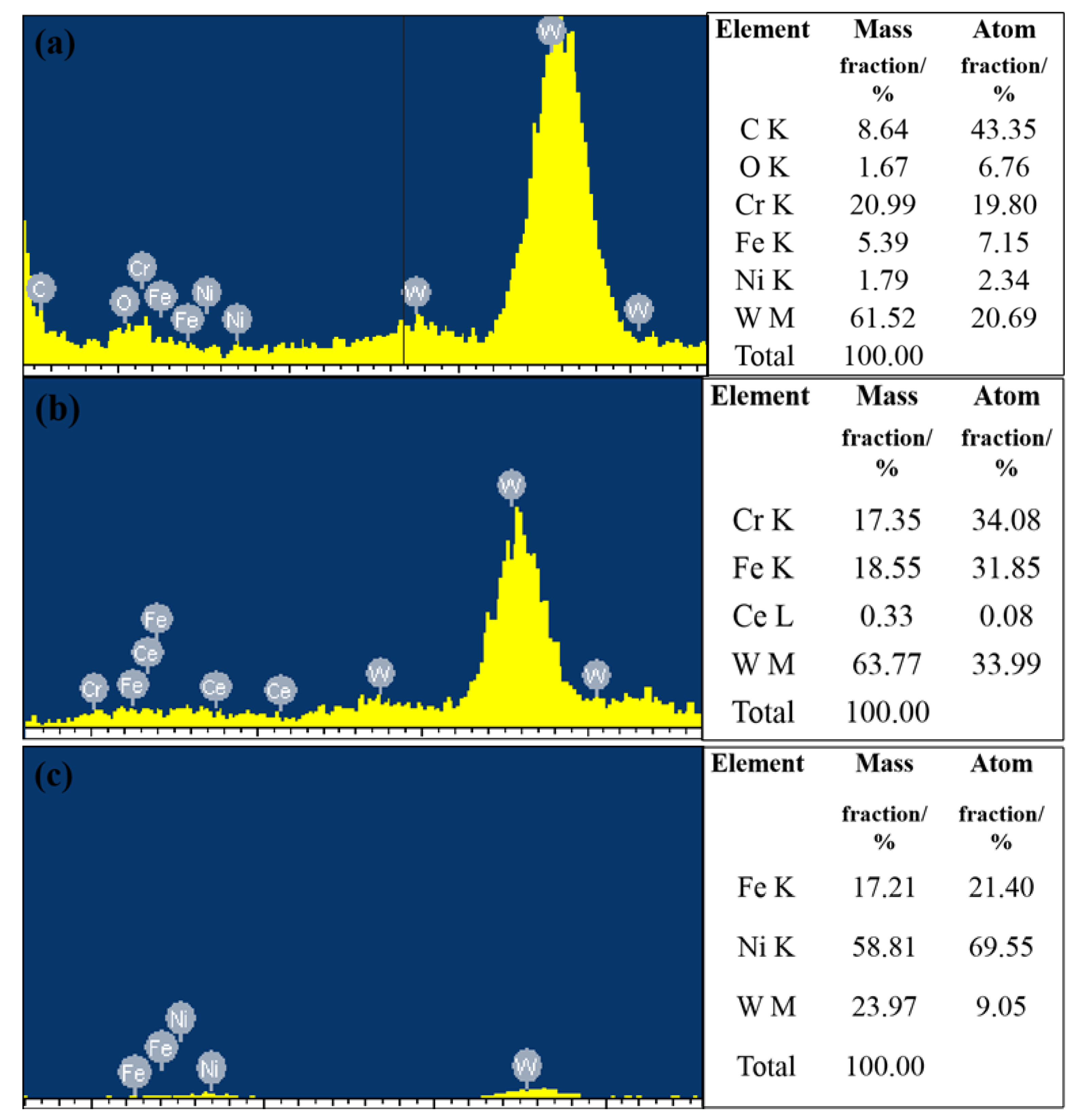
3.3. Microstructural Analysis of the Coatings

Figure 5 shows the cross-sectional SEM images of the modified composite coatings containing different amounts of CeO2. As we can observe from these images, the structures are similar to those of crystal cells or dendrites. The nano-WC-reinforced Ni-based coating contains considerable structural inclusions along with large particle sizes and an uneven distribution. This coating also contains considerably coarse columnar or strip-type crystals with a considerable amount of irregular areas being scattered on the surface. With the addition of the rare earth oxide CeO2, the morphology of the coatings changes drastically. Particularly for the composite coating modified with 0.5% CeO2, the surface contains large strips, cell-like crystals, and dendrites. In case of the composite coating with 1.0% of CeO2, the structural distribution is relatively dense, with more defined dendrites and strip structures, and a larger number of tiny cell crystals are clustered around the edge of the bulk structure. Some clustered cell crystals are also block-shaped. With an increase in the CeO2 content to 1.5%, a large number of block and strip structures are distributed within the coating. The number of cell crystals and dendrites are observed to substantially reduce. Only some fine dendrites and cell crystals exist between the block and strip structures. For a composite coating with 2% CeO2, the structures remain unchanged, apart from the dendrites increasing in size. This is primarily because the presence of excessive rare earth oxide CeO2 has played a role in reducing the fluidity of the molten pool, which causes the deceleration of the convection speed, increases the difficulty associated with the discharge of the inclusions, and decelerates the cooling speed of the molten pool, allowing a considerable amount of time for these structures to proliferate [22].
Figure 6 shows the SEM images of the top and bottom regions as well as the interface of the modified cladding with 1.0% CeO2. From this figure, different parts of the coating are observed to exhibit completely different morphologies. Here, the top region of the coating mainly comprises granular cell-like crystals, and some dendrites are also present. The EDS analysis of these cell-like crystals, dendrites, and massive tissues is presented in Figure 7. The EDS analysis of the granular cell-like crystals proves that these structures mainly comprise atomic C, W, and Cr. In case of dendrites, the EDS spectrum shows the presence of atomic W, Fe, and Cr. The EDS measurement is also performed in case of the massive structures in the coating, revealing the accumulation of atomic Ni, Fe, and W in these structure types. The bottom region of the coating almost entirely comprises dendritic structures, accommodating only some larger structures on the surface. The dendrites in this region are also directionally driven. The bonding area is a fusion zone containing bright white bands, forming a metallurgical binding interface between the surface cladding layer and the substrate. Many large dendrites grow perpendicular to the bright white band and subsequently expand to inside the coating. Also, some of the smaller dendrites attach to the surrounding parts of these large dendrites.

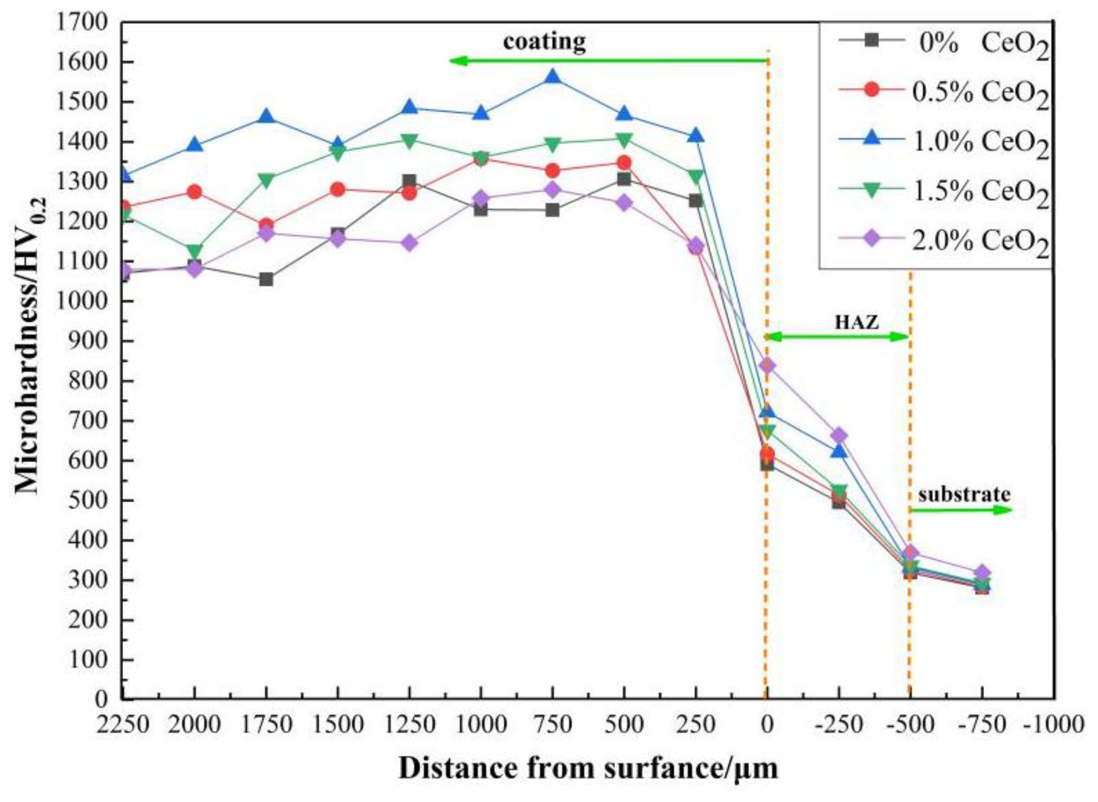
3.4. Microhardness Analysis of the Coatings

The obtained microhardness distribution of the modified composite coatings is presented in Figure 8. Here, the microhardness of the unmodified coating is 1050–1300 HV0.2. The microhardness of the upper part of the cladding is lower by approximately 250 HV0.2 when compared with that in the bottom region. This is due to the slow scanning speed that caused the molten pool to exist for a considerably long period of time. Further, a large amount of WC or tungsten compounds are observed to deposit at the bottom of the coating with the addition of CeO2, and these WC or tungsten compounds distribute uniformly when 1.0% CeO2 is added. In addition, the microhardness of the composite-modified coating initially increased and subsequently decreased. When the mass fraction of CeO2 was 0.5%, the microhardness of the coating began to increase. At 1.0% CeO2, the microhardness reached a maximum of 1560 HV0.2, which is approximately 260 HV0.2 higher than the maximum hardness of the unmodified coating. Meanwhile, a decreased fluctuation range of microhardness can be obtained, which can be attributed to the rare earth oxide CeO2 creating a uniform dispersion strengthening effect with CeNi2 and the carbide M23C6 (M = Fe, Ni, and Cr) in the coating [22]. The microhardness of the coating began to decrease when the CeO2 contents exceeded 1.0%. When CeO2 contents reached 2.0%, the microhardness of the coating began to decrease significantly, where even some parts of the coating showed a lower microhardness compared to that showed by the unmodified coating. The hardness of the coating at the metallurgical binding interface is slightly greater than that of other coatings at the same location, and the hardness of the coating at the heat-affected zone smooth transition. This can be attributed to the microhardness of the coating, which is caused by the combined effect of the structure and dilution rate. When CeO2 is added in excess, the laser energy absorbed by the molten pool increases, increasing the convection and inducing the excessive melting of the substrate. Therefore, a large dilution rate can be observed in the coating, reducing the microhardness of the coating [23]. Thus, the presence of the rare earth oxide CeO2 (1.0%) is considered to be effective to stabilize the coating, increasing the microhardness, reducing the fluctuation range, and causing the uniformity of the hardness distribution in different areas. However, an excessive amount of CeO2 increases the coating dilution rate, which simultaneously decreases the microhardness of the coating.

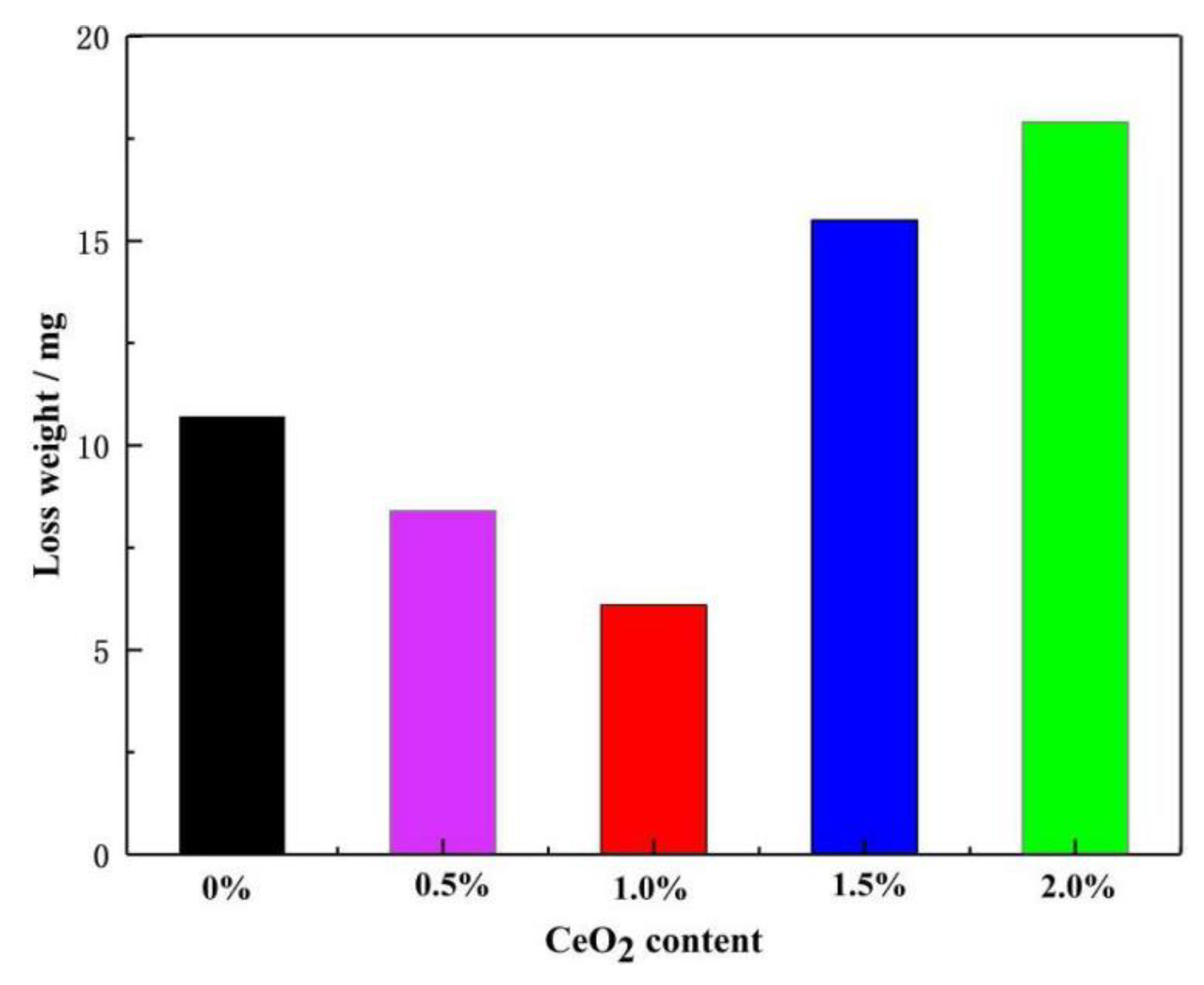
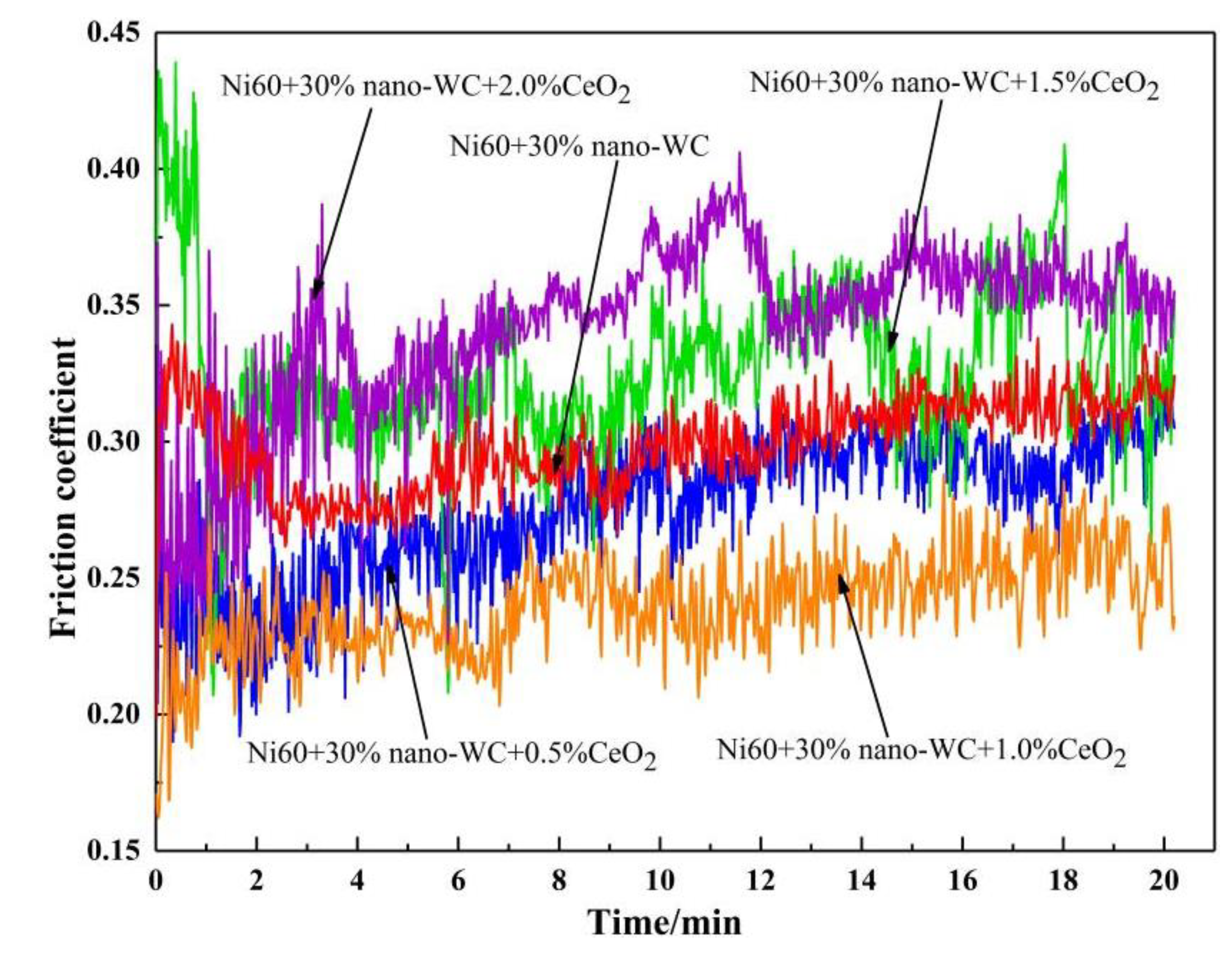
3.5. Wear Resistance Analysis

Figure 9 denotes the varying wear resistances of the modified composite coatings with different mass fractions of CeO2 under high temperatures. The weight losses in case of different coatings initially decrease and subsequently increase with the addition of CeO2 in 20 min, where the specific weight losses are 10.7, 8.4, 6.1, 15.5, and 17.2 mg. The modified composite coating with 1.0% rare earth oxide CeO2 has the lowest weight loss, which is approximately 48% lower than that observed in case of the nano-WC reinforced coatings.
Figure 10 depicts the friction coefficient of the modified composite coatings containing different amounts of CeO2. The frictional coefficient of the coatings exhibits a considerable disparity. With the increased addition of CeO2, the frictional coefficient of each coating gradually decreases before it rapidly increases. With the addition of 0.5% CeO2, the frictional coefficient begins to decrease. At 1.0%, the friction coefficient of the composite-modified coating decreases to approximately 0.23. When CeO2 exceeded 1.0%, the friction coefficient begins to increase significantly and becomes higher than that of the coating without CeO2. At 2.0%, the coating friction coefficient is the largest, and even close to 0.40. The frictional coefficient of the modified composite coatings with less than 1.0% CeO2 only slightly fluctuates with respect to the frictional coefficient value. After a period of 6–7 min, the coating wear becomes stable, and the frictional coefficient curve is also observed to be stable. When the CeO2 contents exceed 1.0%, the friction coefficient curve of the modified composite coatings fluctuates abruptly. Here, the frictional coefficient value changes considerably; however, it has not entered the stable wear stage. This is likely due to the small addition of CeO2 that can effectively refine the reinforcing phases, ensuring the uniform distribution of the dispersal in the cladding layer, resulting in wear-resistant coatings. When the content of CeO2 is too high, the fluidity of the melt in the molten pool is reduced because CeO2 is difficult to melt. Thus, a large amount of CeO2 remains in the coating and forms internal inclusions with other elements, decreasing the density of the inner tissue of the coating, which increases the frictional coefficient of the coatings.
Figure 11 shows the 3D morphology of the friction surface of the modified coatings before and after the addition of CeO2. The wear scars of the modified coatings are arc-shaped, as can be observed from the 3D morphology. The wear depth of the nano-WC reinforced coating without CeO2 is 1–10 μm, where the wear surface obviously spalled. The wear mechanism is principally adhesive wear. Four cross-sectional depth tests conducted on the surface of the wear scar indicate that the surface of coating has an inclination of approximately 10 μm. When comparing the worn part with the adjacent non-abrasive area on the same profile, the depth of the worn area is shallow because the coating surface exhibits high hardness. The depth of the wear surface in the composite coating has sizes of 2–4 μm, resulting in a considerably shallow shape. The presence of slight spalling and the large number of arc-shaped scratches and furrows in the worn surface indicate that the wear mechanism is mainly abrasive, which is accompanied by slight adhesive wear. The depth testing shows that the depth from the surface of the wear scar to the adjacent non-wear area is within 1 μm; some areas of the worn surface are observed to be scratched only by the anti-wear ball, and no wear loss can be observed. This is due to the relative abrasion resistance of the material, which is directly proportional to the hardness. Thus, the higher the hardness, the better will be the abrasion resistance of the material. This is also the reason why the modified composite coatings exhibit only 6.1 mg of wear loss. The comprehensive friction and wear data of the modified composite coatings show that the addition of the appropriate amount of the rare earth oxide CeO2 could significantly improve the wear resistance of the coatings.

4. Conclusions

In this study, we successfully prepared a nano-WC reinforced Ni-based composite coating by adding the rare earth oxide CeO2. The following observations were noted.
(1) The presence of the rare earth oxide CeO2 enhanced the properties of the modified composite coatings. By increasing the CeO2 contents to 1.0%, the number of pores in the coating became minimal.
(2) The main phases in the modified composite coatings were Ni–Fe and W2C. Other phases, including Fe3C, Cr23C6, M6C (M = W, Fe, and Ni), SiC, Cr7C3, Si2W, NiW, CeFe2 and CeNi2, were also obtained.
(3) The structures of the modified composite coatings mainly comprised dendrites, cell-like crystals, strip-shapes, and a bulk crystal structure. The dendrites mainly comprised atomic W, Fe, and Ni. The cell-like crystals contained atomic C, W, and Cr, whereas the bulk structures comprised atomic Cr, Fe, and W. When the mass fraction of CeO2 was 1.0%, the reinforcing phase was evenly dispersed within the cladding layer, where the coatings appeared to be significantly refined and denser.
(4) Within a certain range, an increase in the mass fraction of CeO2 increased the microhardness and reduced the fluctuation range of the coatings. When 1.0% of CeO2 was added, the maximum microhardness of the coating was approximately 1560 HV0.2, which is approximately 260 HV0.2 higher than that of the unmodified coating. However, a mass fraction of more than 1.0% CeO2 increased the coating dilution rate, decreasing the coating microhardness.
(5) To an extent, the addition of the rare earth oxide CeO2 can effectively enhance the wear resistance of the coating. The minimum wear of the coating containing 1.0% CeO2 was 6.1 mg, whereas the minimum frictional coefficient was approximately 0.23. This is much better than that of the unmodified coating. The adhesive wear was the main mechanism for unmodified coatings. The wear mechanism of the modified composite coatings was primarily abrasive wear but was also accompanied by slight adhesive wear.

Author Contributions

Conceptualization: D.S., Z.L. and X.C. (Xiangxiang Cui); methodology: D.S., J.W. and X.C. (Xiangxiang Cui); software: X.C. (Xiangxiang Cui) and X.C. (Xu Chen); validation: D.S. and X.C. (Xiangxiang Cui); formal analysis: X.C. (Xiangxiang Cui); investigation: X.C. (Xu Chen), S.D. and W.S.; resources: Z.L. and D.S.; data curation: J.W., X.C. (Xiangxiang Cui); writing—original draft preparation: D.S., J.S. and X.C. (Xiangxiang Cui); writing—review and editing: D.S., J.S. and X.C. (Xiangxiang Cui); project administration: D.S., J.S. and J.W.; funding acquisition: D.S., J.S. and J.W. All authors have read and agreed to the published version of the manuscript.

Funding

This work was financially supported by the Nature Science Fund of Anhui Province (Grant No. 1908085ME128), the Anhui polytechnic university middle younger top-notch talent planned project of 2018, the Nature Science Foundation of Education Department of Anhui province (Grant No. KJ2018A0123), Key Projects of the University Talent Support Program (Grant No. gxyqZD19051), and the Open Fund of Shanghai Key Laboratory of Materials Laser Processing and Modification (Grant No. MLPM2017-3).

Conflicts of Interest

The authors declare no conflicts of interest.

References

  1. Ju, J.; Zhou, Y.; Kang, M.; Wang, J. Optimization of Process Parameters, Microstructure, and Properties of Laser Cladding Fe-Based Alloy on 42crmo Steel Roller. Materials 2018, 11, 2061. [Google Scholar] [CrossRef] [PubMed] [Green Version]
  2. Liu, X.B.; Yu, G.; Guo, J.; Gu, Y.J.; Pang, M.; Zhang, C.Y.; Wang, H.H. Research on Laser Welding of Cast Ni-Based Superalloy K418 Turbo Disk and Alloy Steel 42crmo Shaft. J. Alloys Compd. 2008, 453, 371–378. [Google Scholar] [CrossRef] [Green Version]
  3. Ding, Y.; You, G.; Wen, H.; Li, P.; Tong, X.; Zhou, Y. Microstructure and Mechanical Properties of Inertia Friction Welded Joints between Alloy Steel 42crmo and Cast Ni-Based Superalloy K418. J. Alloys Compd. 2019, 803, 176–184. [Google Scholar] [CrossRef]
  4. Sola, R.; Giorgia Poli, P.V.; Roberto, G. Effects of Surface Morphology on the Wear and Corrosion Resistance of Post-Treated Nitrided and Nitrocarburized 42CrMo4 Steel. Metall. Mater. Trans. A 2014, 45, 2827–2833. [Google Scholar] [CrossRef]
  5. Yuan, Y.; Li, Z. Growth Mechanism of in-Situ WC Grain in Fe-Ni-WC Alloys System. J. Alloys Compd. 2018, 738, 379–393. [Google Scholar] [CrossRef]
  6. Yuan, Y.; Wu, H.; You, M.; Li, Z.; Zhang, Y. Improving Wear Resistance and Friction Stability of Feni Matrix Coating by in-Situ Multi-Carbide WC-TiC Via Pta Metallurgical Reaction. Surf. Coat. Technol. 2019, 378, 124957. [Google Scholar] [CrossRef]
  7. Hu, C.; Zhi, G.F.; Xian, R.Z.; Sheng, D.; Yi, J. Effect of Laser Cladding Technologies on Microstructure and Properties of Ni-Based WC Alloy Coatings. Adv. Mater. Res. 2011, 314–316, 245–248. [Google Scholar] [CrossRef]
  8. Zhao, Y.; Sun, J.; Li, J. Effect of Rare Earth Oxide on the Properties of Laser Cladding Layer and Machining Vibration Suppressing in Side Milling. Appl. Surf. Sci. 2014, 321, 387–395. [Google Scholar] [CrossRef]
  9. Tang, K.; Ding, Z.; Li, C. Microstructure and Abrasive Wear Resistance of Nano-WC Reinforced Ni-Based Alloy Spray-Melted Coatings. Surf. Technol. 2017, 8, 7. [Google Scholar]
  10. Yao, S.; Su, Y.; Gao, W.; Cheng, K. Tribological Performance of Nano-Structured WC Reinforced Ni-Based Alloy Hvof Coatings. Mocaxue Xuebao / Tribol. 2008, 28, 38. [Google Scholar]
  11. Benea, L.; Sorin-Bogdan Başa, E.D.; Nadège Caron, O.R.; Pierre, P.; Jean-Pierre, C. Fretting and Wear Behaviors of Ni/Nano-WC Composite Coatings in Dry and Wet Conditions. Mater. Des. 2015, 65, 550–558. [Google Scholar] [CrossRef]
  12. Farahmand, P.; Liu, S.; Zhang, Z.; Radovan, K. Laser Cladding Assisted by Induction Heating of Ni–WC Composite Enhanced by Nano-WC and La2O3. Ceram. Int. 2014, 40, 15421–15438. [Google Scholar] [CrossRef]
  13. Cui, Y. Study on the Effect of Rare Earth Elements on the Microstructure and Performance of Cladding Layer. Appl. Mech. Mater. 2014, 608–609, 1035–1038. [Google Scholar] [CrossRef]
  14. Song, X.; Lei, W.; Yang, L. Effects of Temperature and Rare Earth Content on Oxidation Resistance of Ni-Based Superalloy. Prog. Nat. Sci.: Mater. Int. 2011, 21, 227–235. [Google Scholar] [CrossRef] [Green Version]
  15. Wang, W.; Chen, Z.; Feng, S. Effect of Ceo2 on Impact Toughness and Corrosion Resistance of Wc Reinforced Al-Based Coating by Laser Cladding. Materials 2019, 12, 2901. [Google Scholar] [CrossRef] [Green Version]
  16. Fang, Y.; Cui, X.; Cai, Z.; Wang, C.; Guo, J. Influence of La2O3 Addition on Nano Indentation Hardness and Residual Stress of Stellite 6 Coating Prepared by Plasma Cladding. J. Rare Earths 2018, 36, 873–878. [Google Scholar] [CrossRef]
  17. Song, S.G.; Wang, W.; Tan, S.L.; Wang, L. Effect of Rare Earth Doped with Nd2O3 on Microstructure and Properties of Ysz / (Ni, Al) Composite Coatings. Surf. Technol. 2016, 45, 49–55. [Google Scholar]
  18. Li, M.; Han, B.; Wang, Y.; Pu, K. Effects of La2o3 on the Microstructure and Property of Laser Cladding Ni-Based Ceramic Coating. Optik 2017, 130, 1032–1037. [Google Scholar] [CrossRef]
  19. Li, J.; Luo, X.; Li, G.J. Effect of Y2O3 on the Sliding Wear Resistance of TiB/TiC-Reinforced Composite Coatings Fabricated by Laser Cladding. Wear 2014, 310, 72–82. [Google Scholar] [CrossRef]
  20. Zhao, N.; Li, T.; Guo, H.; Zhang, M. Microstructure and Wear Resistance of Laser Cladded Ni-Based Coatings with Nanometer La2O3 Addition. Rare Metal Mater. Eng. 2017, 46, 2092–2096. [Google Scholar] [CrossRef] [Green Version]
  21. Jiang, J.; Cheng, Y.; H, X.; Lian, G.; Chen, C. Performance of WC Reinforced Ni-Based Coating on 45 Steel Surface by Laser Cladding. Appl. LASER 2019, 39, 24–34. [Google Scholar]
  22. Deen, K.M.; M Afzal, Y.; Liu, A.; Farooq, A.A.; Asselin, E. Improved Corrosion Resistance of Air Plasma Sprayed WC-12% Co Cermet Coating by Laser Re-Melting Process. Mater. Lett. 2017, 191, 34–37. [Google Scholar] [CrossRef]
  23. Ye, H.; Zhang, X.B.; Xue, Z.F.; Fan, Y.H.; Chen, K. Effect of CeO2 on Microstructure and Properties of WC/Ni60 Coating by Laser Cladding. Appl. Mech. Mater. 2009, 79–82, 795–798. [Google Scholar]
Figure 1. Morphology of the experimental powders: (a) Ni60, (b) nano-WC, and (c) CeO2.
Metals 10 00383 g001
Figure 2. Surface morphology of the samples containing different amounts of CeO2: (a) 0%, (b) 0.5%, (c) 1.0%, (d) 1.5%, and (e) 2.0%.
Metals 10 00383 g002
Figure 3. Morphology of the cladding layer with differing CeO2 contents: (a) 0.0%, (b) 0.5%, (c) 1.0%, (d) 1.5%, and (e) 2.0%.
Metals 10 00383 g003
Figure 4. XRD patterns of the composites modified with different coatings.
Metals 10 00383 g004
Figure 5. SEM images of the CeO2-modified coatings: (a) 0.0%, (b) 0.5%, (c) 1.0%, (d) 1.5%, and (e) 2.0%.
Metals 10 00383 g005aMetals 10 00383 g005b
Figure 6. SEM images of certain areas of the composite coating containing 1.0% CeO2: (a) coating, (b) top, (c) bottom, and (d) interface.
Metals 10 00383 g006aMetals 10 00383 g006b
Figure 7. Energy dispersive spectroscopy (EDS) spectra of the different microstructural formations on the surface of the coating with 1.0% CeO2: (a) cell-like crystals, (b) dendrites, and (c) the bulk structure.
Metals 10 00383 g007
Figure 8. The microhardness distribution curve for the CeO2-modified composite coatings with different mass fractions.
Metals 10 00383 g008
Figure 9. Wear loss weight changes in modified composite coatings containing different amounts of CeO2.
Metals 10 00383 g009
Figure 10. Frictional coefficient of the modified composite coatings containing different amounts of CeO2.
Metals 10 00383 g010
Figure 11. 3D morphology of the friction surface with the modified coatings before and after the addition of the rare earth oxide CeO2: (a) unmodified coating and (b) 1.0% CeO2.
Metals 10 00383 g011aMetals 10 00383 g011b
Table 1. Chemical composition of the 42CrMo steel (wt. %).
CSiMnPSCuCrMoFe
0.38~0.450.20~0.400.50~0.80≤0.04≤0.04≤0.300.90~1.200.15~0.25BaL
Table 2. Chemical composition of the Ni60 alloy (wt. %).
CCrSiBFeNi
0.5~1.014~183.5~5.03.0~4.57.0~10.0BaL
Table 3. Cladding material ratio (wt. %).
NO.Ni60nano-WCCeO2
170.0030.000.00
269.6529.850.50
369.3029.701.00
468.9529.551.50
568.6029.402.00
Table 4. The detailed parameter of the friction and wear experiment.
Experiment ParameterDetailed Values
Motor frequency10 Hz
Spinning speed500 rpm
Operating temperature400°C
Load19.8 N
Time20 min

