Numerical Study of the Influence of Geometric Features of Dimple Texture on Hydrodynamic Pressure Generation


Abstract
1. Introduction
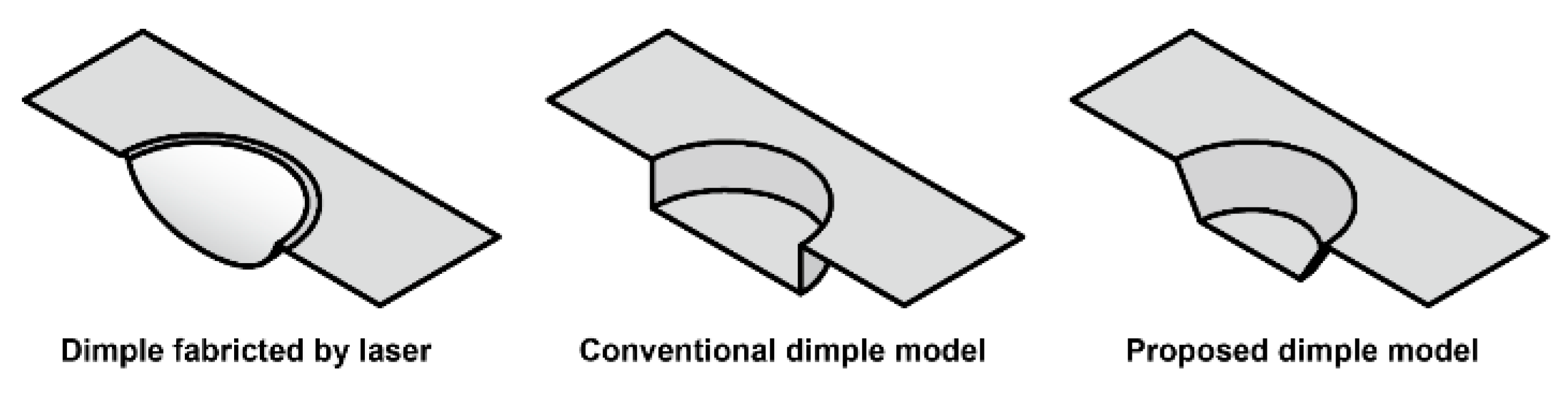
2. Modeling Dimples
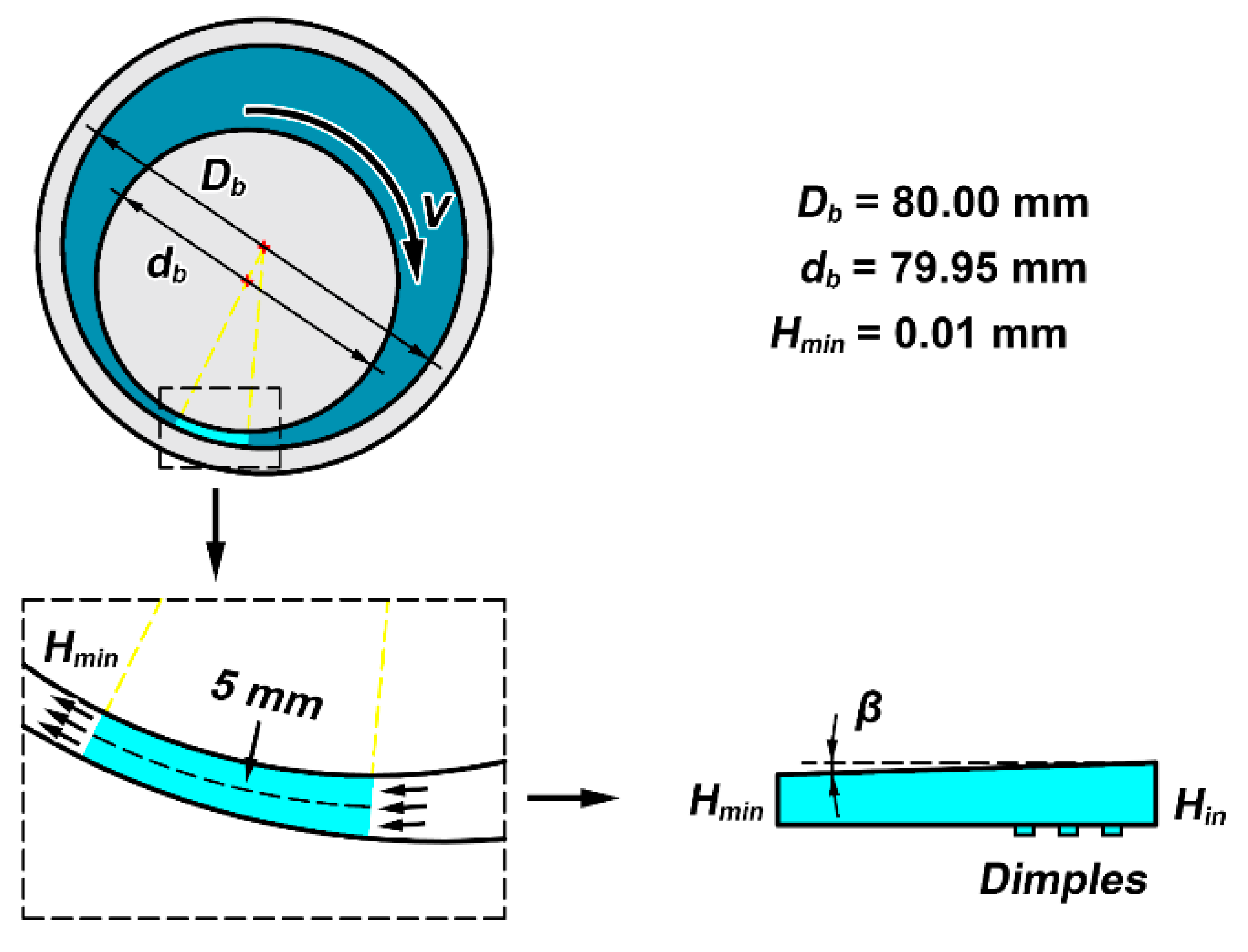
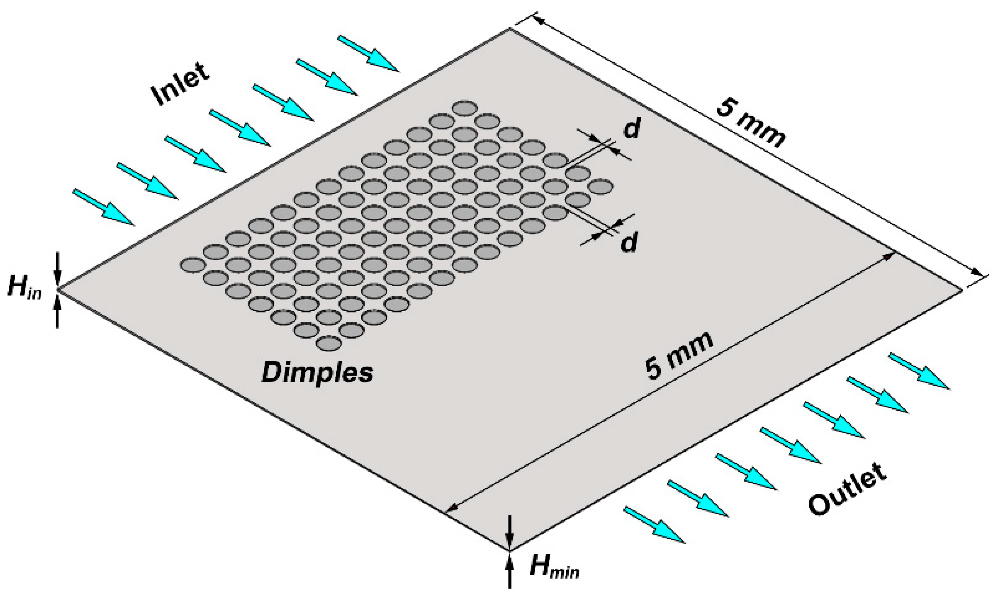
3. Numerical Modeling
- The flow is considered as laminar, incompressible, and isothermal.
- The influence of a solid structure formation due to the flow pressure is negligible.
- Film thickness change due to the texture is negligible.
4. Results and Discussion
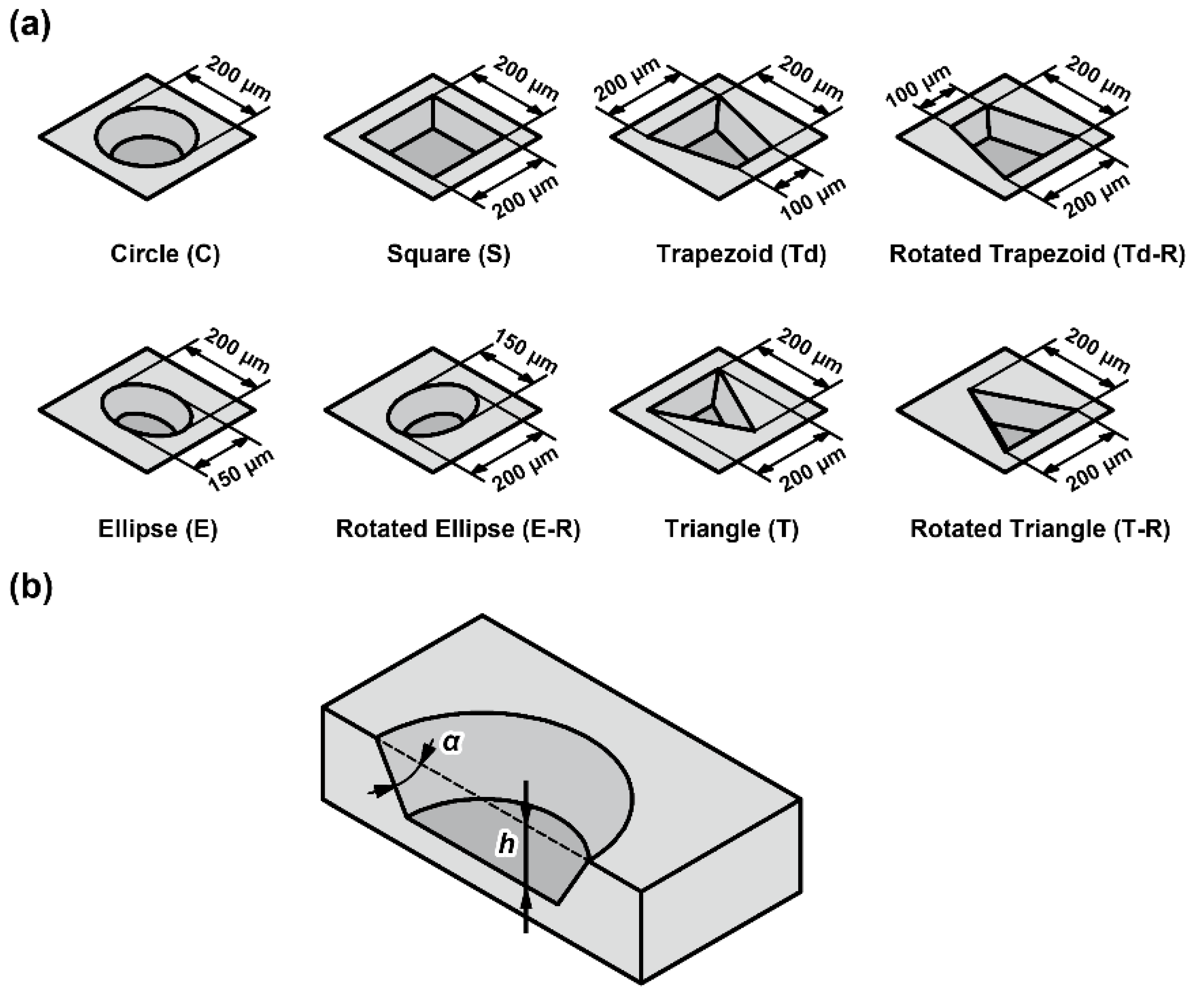
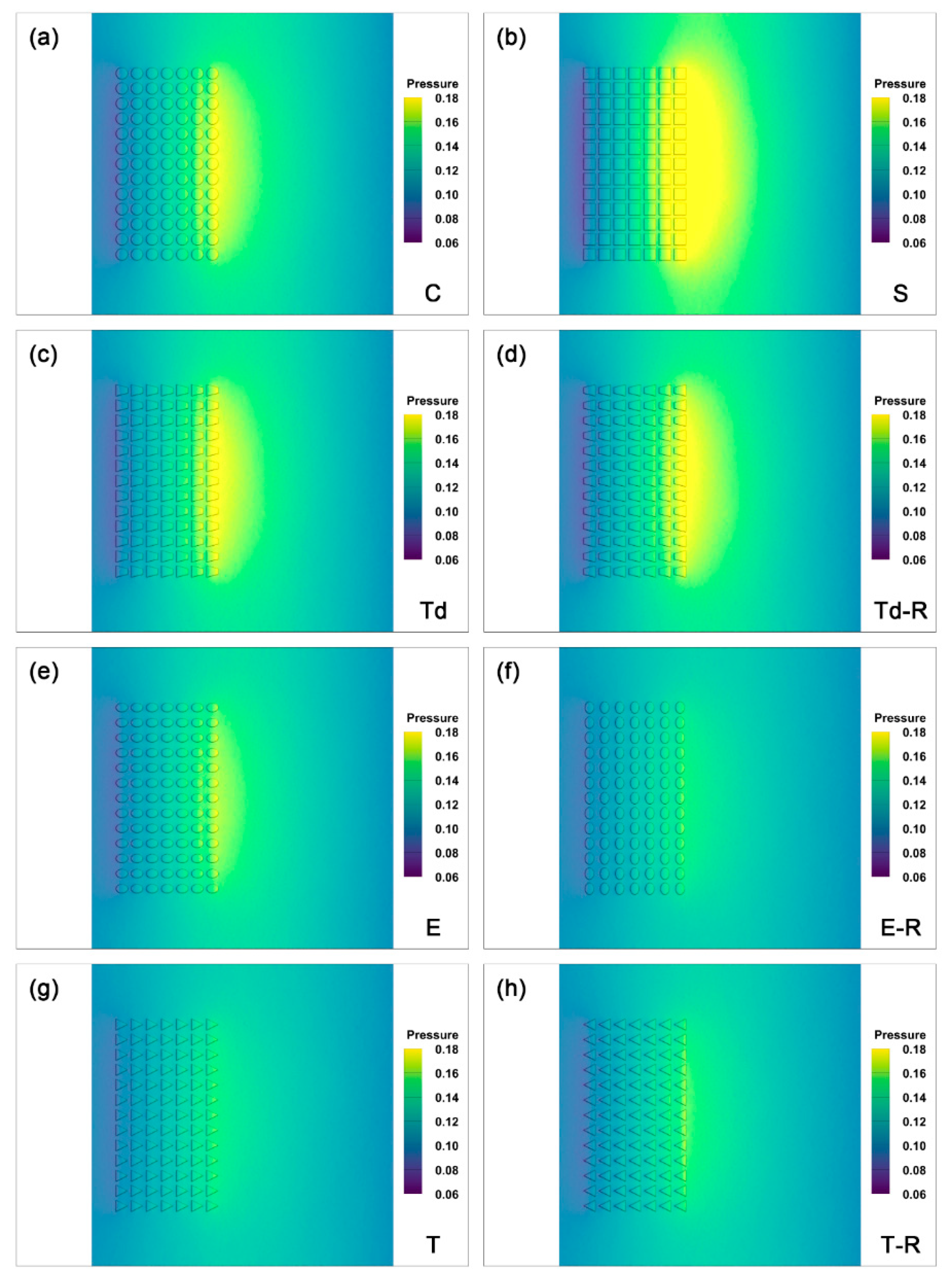
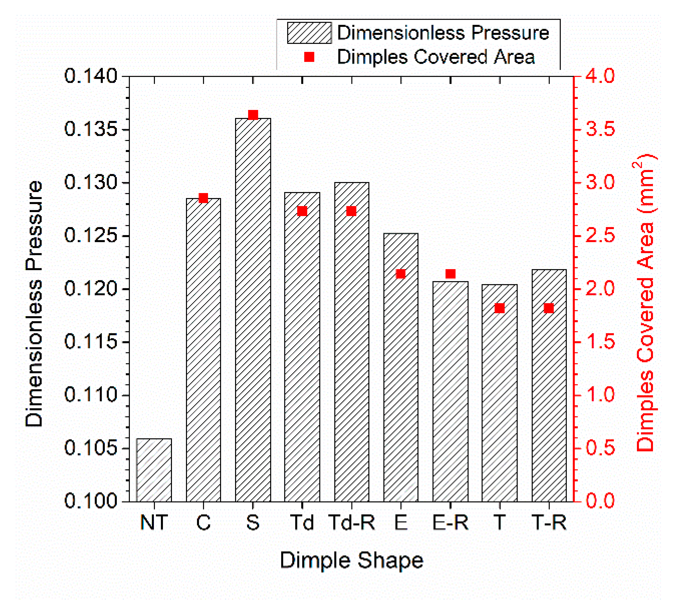
4.1. Effect of Dimple Shape
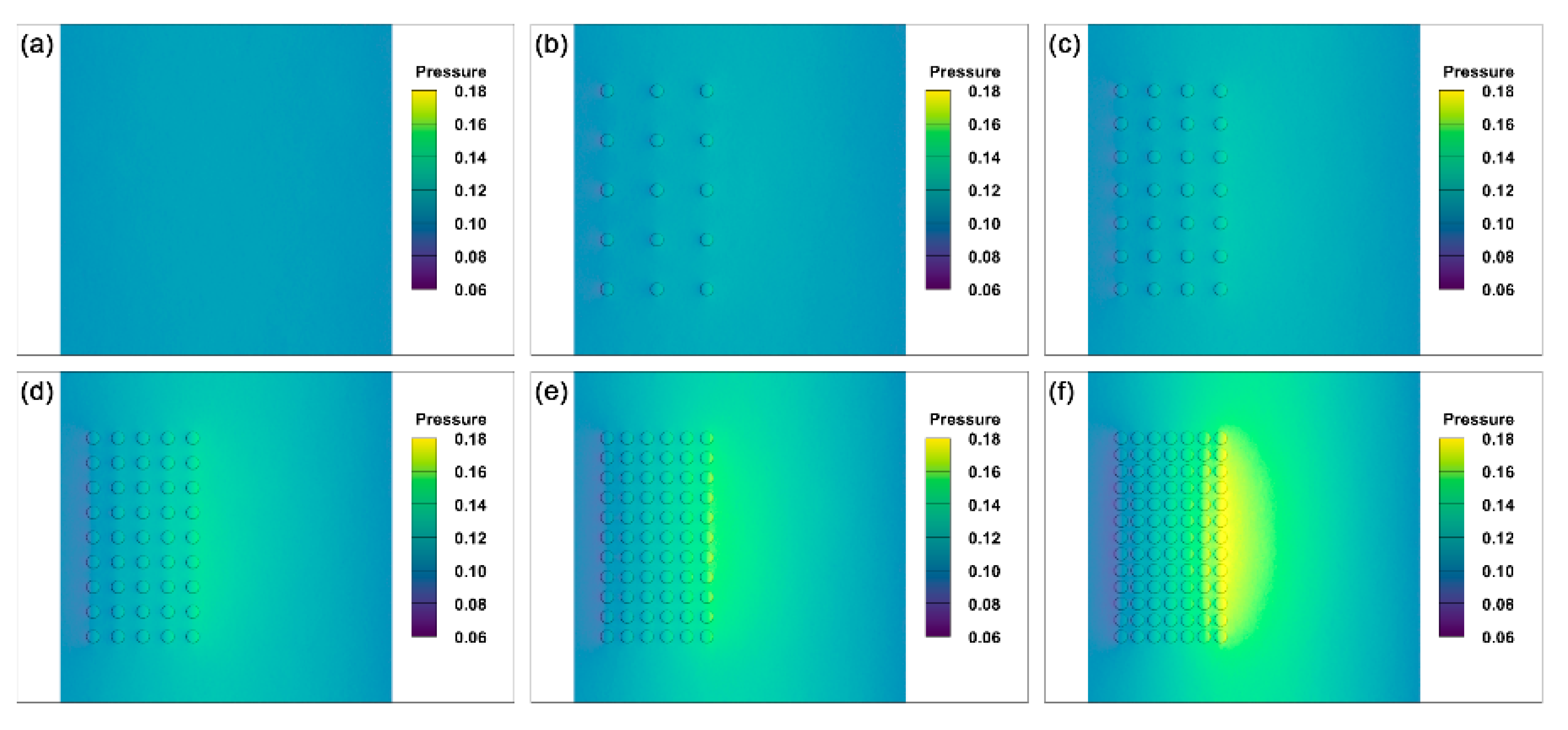
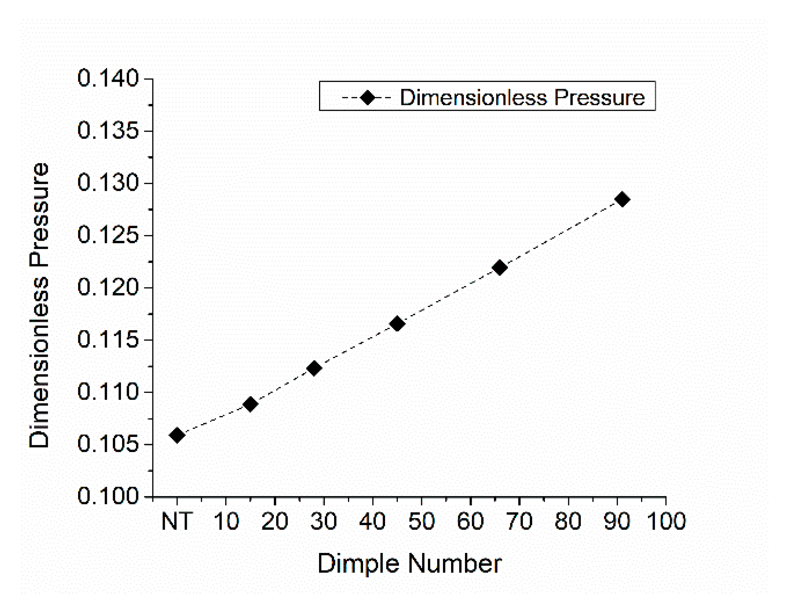
4.2. Effect of Dimple Density
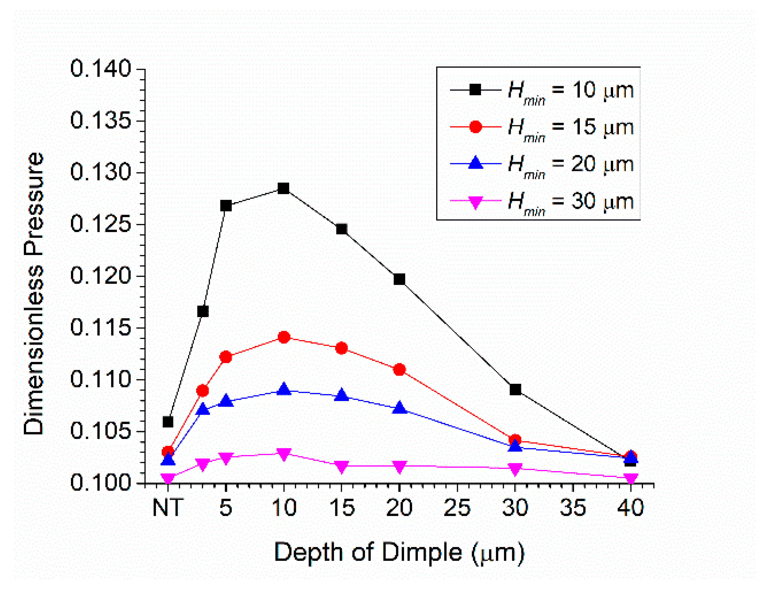
4.3. Effect of Dimple Depth
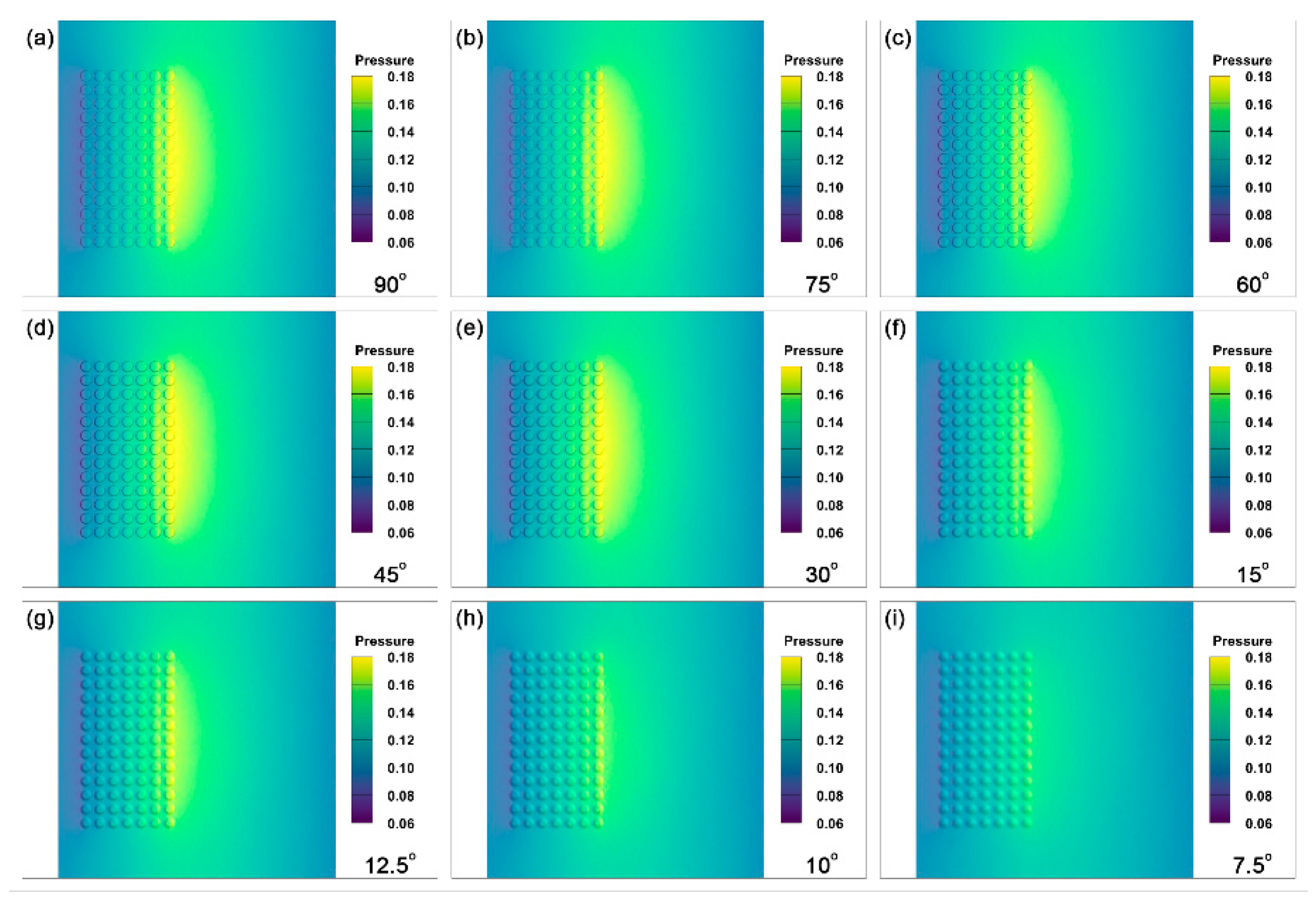
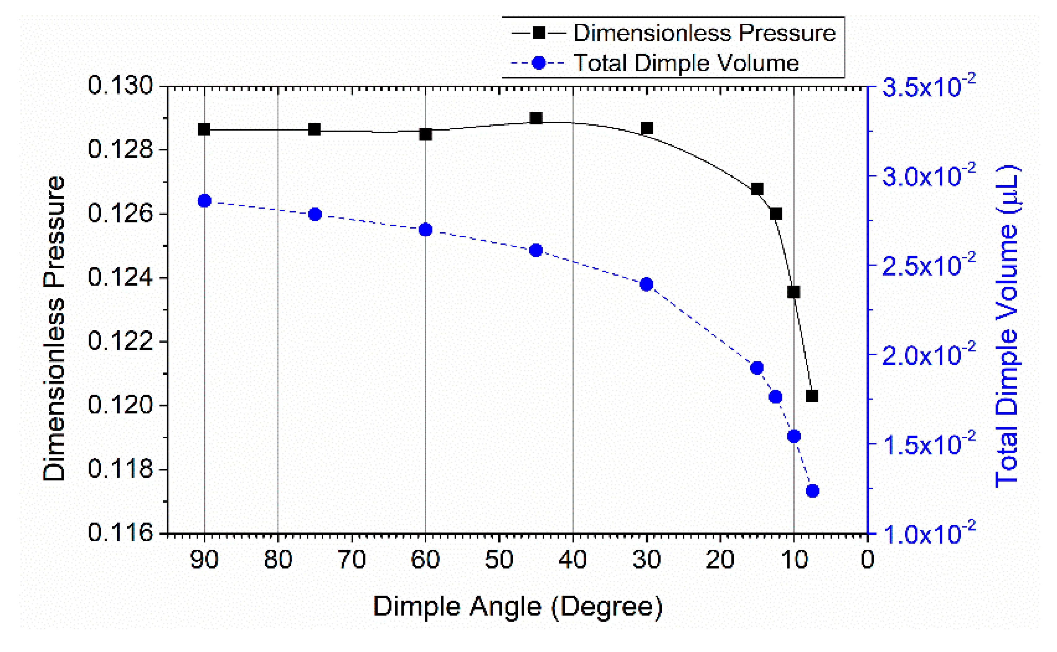
4.4. Effect of Dimple Surface Angle
5. Conclusions
- The dimple texture effect increases linearly as density increases.
- An optimal dimple depth is identified with a certain minimum film thickness. In this study, 10 µm is an optimal value when the minimum film thickness is 10, 15, 20, and 30 µm.
- As the minimum film thickness increases from 10 to 30 µm, the effect of dimple texture is minimized.
- The introduced dimple surface angle influences the dimple texture effect. The most significant changes occur when the dimple surface angle is smaller than .
Author Contributions
Funding
Conflicts of Interest
References
- Holmberg, K.; Erdemir, A. Influence of tribology on global energy consumption, costs and emissions. Friction 2017, 5, 263–284. [Google Scholar] [CrossRef]
- Gropper, D.; Wang, L.; Harvey, T.J. Hydrodynamic lubrication of textured surfaces: A review of modeling techniques and key findings. Tribol. Int. 2016, 94, 509–529. [Google Scholar] [CrossRef]
- Stepień, P. Deterministic and stochastic components of regular surface texture generated by a special grinding process. Wear 2011, 271, 514–518. [Google Scholar] [CrossRef]
- Nanbu, T.; Ren, N.; Yasuda, Y.; Zhu, D.; Wang, Q.J. Micro-textures in concentrated conformal-contact lubrication: Effects of texture bottom shape and surface relative motion. Tribol. Lett. 2008, 29, 241–252. [Google Scholar] [CrossRef]
- Ramesh, A.; Akram, W.; Mishra, S.P.; Cannon, A.H.; Polycarpou, A.A.; King, W.P. Friction characteristics of microtextured surfaces under mixed and hydrodynamic lubrication. Tribol. Int. 2013, 57, 170–176. [Google Scholar] [CrossRef]
- Tomanik, E. Modelling the hydrodynamic support of cylinder bore and piston rings with laser textured surfaces. Tribol. Int. 2013, 59, 90–96. [Google Scholar] [CrossRef]
- Hamilton, D.B.; Walowit, J.A.; Allen, C.M. A theory of lubrication by microirregularities. J. Fluids Eng. Trans. ASME 1966, 88, 177–185. [Google Scholar] [CrossRef]
- Arghir, M.; Roucou, N.; Helene, M.; Frene, I. Theoretical analysis of the incompressible laminar flow in a macro-roughness cell. J. Tribol. 2003, 125, 309–318. [Google Scholar] [CrossRef]
- Papadopoulos, C.I.; Kaiktsis, L.; Fillon, M. Computational fluid dynamics thermohydrodynamic analysis of three-dimensional sector-pad thrust bearings with rectangular dimples. J. Tribol. 2014, 136, 1–11. [Google Scholar] [CrossRef]
- Zhang, X.; Yin, Z.; Jiang, D.; Gao, G. The design of hydrodynamic water-lubricated step thrust bearings using CFD method. Mech. Ind. 2014, 15, 197–206. [Google Scholar] [CrossRef]
- Jiang, J.; Peng, X.; Zong, C.; Zhao, W.; Chen, Y.; Li, J. Enhancing Film Stiffness of Spiral Groove Dry Gas Seal via Shape Modification at Low Speed: Numerical Results and Experiment. Tribol. Trans. 2019, 62, 931–942. [Google Scholar] [CrossRef]
- Shimizu, T.; Kobayashi, H.; Vorholt, J.; Yang, M. Lubrication analysis of micro-dimple textured die surface by direct observation of contact interface in sheet metal forming. Metals 2019, 9, 917. [Google Scholar] [CrossRef]
- Machrafi, H. Green Energy and Technology; Bentham Science Publishers: SHJ, ARE, 2012; ISBN 9781608054220. [Google Scholar]
- Schnerr, G.H.; Sauer, J. Physical and numerical modeling of unsteady cavitation dynamics. In Proceedings of the 4th International Conference on Multiphase Flow, New Orleans, NO, USA, 27 May–1 June 2001; pp. 1–12. [Google Scholar]
- Dobrica, M.B.; Fillon, M.; Pascovici, M.D.; Cicone, T. Optimizing surface texture for hydrodynamic lubricated contacts using a mass-conserving numerical approach. Proc. Inst. Mech. Eng. Part J J. Eng. Tribol. 2010, 224, 737–750. [Google Scholar] [CrossRef]
- Chen, Y.; Wang, J.; Chen, M. Enhancing the machining performance by cutting tool surface modifications: A focused review. Mach. Sci. Technol. 2019, 23, 477–509. [Google Scholar] [CrossRef]
- Sahlin, F.; Glavatskih, S.B.; Almqvist, T.; Larsson, R. Two-dimensional CFD-analysis of micro-patterned surfaces in hydrodynamic lubrication. J. Tribol. 2005, 127, 96–102. [Google Scholar] [CrossRef]
- Tønder, K. Dynamics of rough slider bearings: Effects of one-sided roughness/waviness. Tribol. Int. 1996, 29, 117–122. [Google Scholar] [CrossRef]
- Tønder, K. Hydrodynamic effects of tailored inlet roughnesses: Extended theory. Tribol. Int. 2004, 37, 137–142. [Google Scholar] [CrossRef]


| Case | Dimple Shape | Dimple Depth | Dimple Number | Dimple Surface Angle | Film Thickness |
|---|---|---|---|---|---|
| 4.1 | Circle, square, etc. | 10 µm | 91 | 60° | 10 µm |
| 4.2 | Circle | 10 µm | 15~91 | 60° | 10 µm |
| 4.3 | Circle | 3~40 µm | 91 | 60° | 10~30 µm |
| 4.4 | Circle | 10 µm | 91 | 90~7.5° | 10 µm |
| Physical Properties | Value | Unit |
|---|---|---|
| Density of water | ||
| Dynamic viscosity of water | ||
| Saturated water pressure | ||
| Density of water vapour | ||
| Dynamic viscosity of water vapour |
| Case | Range of Depth | Average Depth | Dimensionless Pressure |
|---|---|---|---|
| a | 10 µm | 10 µm | 0.128 |
| b | 9~11 µm | 10 µm | 0.128 |
| c | 7~13 µm | 10 µm | 0.128 |
| d | 5~15 µm | 10 µm | 0.127 |
© 2020 by the authors. Licensee MDPI, Basel, Switzerland. This article is an open access article distributed under the terms and conditions of the Creative Commons Attribution (CC BY) license (http://creativecommons.org/licenses/by/4.0/).
Share and Cite
Wei, Y.; Tomkowski, R.; Archenti, A. Numerical Study of the Influence of Geometric Features of Dimple Texture on Hydrodynamic Pressure Generation. Metals 2020, 10, 361. https://doi.org/10.3390/met10030361
Wei Y, Tomkowski R, Archenti A. Numerical Study of the Influence of Geometric Features of Dimple Texture on Hydrodynamic Pressure Generation. Metals. 2020; 10(3):361. https://doi.org/10.3390/met10030361
Chicago/Turabian StyleWei, Yuan, Robert Tomkowski, and Andreas Archenti. 2020. "Numerical Study of the Influence of Geometric Features of Dimple Texture on Hydrodynamic Pressure Generation" Metals 10, no. 3: 361. https://doi.org/10.3390/met10030361
APA StyleWei, Y., Tomkowski, R., & Archenti, A. (2020). Numerical Study of the Influence of Geometric Features of Dimple Texture on Hydrodynamic Pressure Generation. Metals, 10(3), 361. https://doi.org/10.3390/met10030361