Article

Study of Zn6Al6Ag Alloy Application in Ultrasonic Soldering of Al2O3–(Al/Al2O3) Joints

1
Faculty of Materials Science and Technology Trnava, Slovak University of Technology in Bratislava, Jána Bottu No. 2781/25, 917 24 Trnava, Slovakia
2
FMT—Faculty of Materials Science and Technology, 17. listopadu 15, 708 33 Ostrava, Poruba, Czech Republic
*
Author to whom correspondence should be addressed.
Metals 2020, 10(3), 343; https://doi.org/10.3390/met10030343
Submission received: 23 January 2020 / Revised: 27 February 2020 / Accepted: 1 March 2020 / Published: 4 March 2020

Abstract

:
The aim of this research is to characterize the soldering alloy Zn6Al6Ag, and to study the ultrasonic soldering of an Al2O3/metal–ceramic composite (Al/Al2O3). Zn6Al6Ag solder presents a quasi-eutectic structure with a melting point around 425 °C. The solder microstructure consists of a (Zn) + (Al) matrix, reinforced with a silver AgZn3 phase. A bond with the metal–ceramic composite was formed due to the dissolution of Al in the liquid Zn solder. The Al2O3 particles were put into motion, and a new composite was formed on the boundary. The Zn6Al6Ag solder also wetted the surface of the Al2O3 ceramic. A decisive effect on bond formation was caused by zinc and aluminum, whose oxides were combined with the oxides of ceramic material during in-air soldering. An adhesive bond was formed. The average joint shear strength of Al2O3/metal–ceramic composite (Al/Al2O3) was found to be 23 MPa.

1. Introduction

Demand is growing for thermally controlled materials in microelectronics. Semiconductors stimulated the development of sophisticated metal–ceramic composites (MMC) with high thermal conductivity (TC) for efficient heat dissipation, and adjustable coefficient of thermal expansivity (CTE) to minimize thermal stresses. This is of principal significance for enhancing the power efficiency, life cycle, and reliability of electronic equipment.
Because the specific TC (TC divided by density) of Al-based composites is high, they are desirable for applications, such as in the aviation industry, where low mass is also desirable [1,2]. Materials used for packaging underwent immense development, owing to many key factors: an increase in the density of packages, greater demand for reliability, growing use of large semiconductor materials with phase arrays, and strict weight limitations for onboard components and many other systems [3].
From the viewpoint of packaging technology, it is essential that electronic devices are capable of operating faster with smaller dimensions and with lower weight.
For this reason, along with the composite materials, new technologies for packaging with high-temperature solders are also applied. This concerns technologies such as ball grid arrays (BGAs), flip-chip technology (C4), chip-scale packaging (CSP), and/or multi-chip modules (MCMs) [4].
The development of high-temperature solders is a major challenge, mainly due to the ban imposed on the use of lead and other elements that are detrimental to health and the environment. At present, there are only a limited number of lead-free soldering alloys available that could, at least partially, substitute for high-lead solders [5]. The alternative alloy systems are hypo-eutectic Bi–Ag, Sb–Sn, or Au–Sn alloys [6,7]. Other alloy systems comprise Zn–Al alloys (alloyed with Mg, Ge, Ga, Sn, and Bi).
These alloys are very attractive from the perspective viewpoint, because Zn is even less expensive than Pb. A small addition of Mg or Ga to this alloy lowers the melting point and forms a ternary alloy that preserves the desired solidification criteria for soldering at higher application temperatures [8,9,10]. Zn–Al-based alloys intended for the electronic industry offer a suitable melting range, as well as good TC and electrical conductivity.
This is why it was selected by the authors of Reference [11] as the basis for their study. They added the Mg and Ga elements to that alloy and, thus, developed the Zn4Al3Mg3Ga alloy. Copper and silicon were used as substrate materials, which were metallized with a Ti/Ni/Ag layer.
Soldering was performed at 370 to 400 °C. The ZnAlMgGa/Cu joints attained a shear strength between 21.8 and 29.4 MPa at soldering temperatures between 370 and 400 °C. This is a comparable joint strength value to that of the Pb5Sn/Cu joint, which attained a value of 28.2 MPa.
The research in Reference [12] dealt with four Zn-based alloys (Zn6Al, Zn6Al1Ga, Zn3Al3Mg, and Zn4Al3Ga3Mg), which could be good substitutes for a classic high-lead solder. Their microstructure and mechanical properties were studied. The authors found that the main cause of solder embrittlement was the thermal dependence of Ga solubility in the hexagonal lattice (hcp) of zinc, in combination with the affinity of Ga for the surface of phases enriched by Al and Zn. This embrittlement may be suppressed by lowering the solubility at higher temperatures. Studies [12,13] dealt with similar issues, where Sn, In, and Ga elements were added to solder types Zn–Al–Mg and Zn–Al–Ge. However, improvement of properties by this alloying was not proven.
Other authors also studied the soldering of ceramic materials with Zn-based solders. For example, in Reference [14], the direct soldering of SiC ceramic by ultrasound assistance was studied. Ceramic SiC substrates were soldered with Zn8.5Al1Mg solder in air at 420 °C. Shear strength increased with prolonged ultrasound assistance. The highest strength (148.1 MPa) was achieved with an ultrasound assistance of 8 s.
In Reference [15], the authors studied the soldering of sapphire (crystalline form of Al2O3) with ultrasound assistance. Zn4Al solder was used.
A composite interlayer of SiCp/A356 was applied in order to reduce the coefficient of thermal expansion of the soldered joint. The application of this interlayer also resulted in a significant increase in joint shear strength to approximately 155 MPa. This represented an increase of about 250% compared to joints that used only Zn–Al alloy.
Issues related to soldering SiC/Al composite with Zn–Al-based solders were studied by the authors of Reference [15]. In order to assure wetting, they employed ultrasound with a 20 kHz frequency. After ultrasound activation, the transfer of SiC particles to the molten solder was observed. Shear strength increased with increasing soldering temperatures. The authors attributed this to an increasing content of Al and volume proportion of reinforcing particles in the joint. Research on application of the same composite material (SiC) was also carried out by the authors of Reference [16]. In order to improve the strength of joints, an Ni layer was deposited on the composite, ensuring better wetting of Zn-based solder (Zn–Cd–Ag–Cu) with melting at approximately 400 °C.
A number of authors [17,18,19,20] showed that solder reactions with metal ceramic composites are preferably oriented to the matrix, which was aluminum in those cases. The selection of soldering alloy is, therefore, aimed toward materials used for Al soldering. Vacuum soldering technology may also be suitable for the fluxless soldering of composites. This issue was studied by the authors of References [21,22,23,24,25]. However, the time required for soldered joint fabrication was on the order of several tens of minutes and, in some cases, hours. By comparison, joints can be fabricated by ultrasound in just a few minutes (often in less than 5 min).
The research in this work is devoted to the characterization of Zn6Al6Ag solder for soldering at high application temperatures. Microstructure, phase composition, temperature of phase transformations, and tensile strength were all studied. This work deals with the application of Zn6Al6Ag solder for ultrasonic soldering of Al2O3/composite (Al/Al2O3) combinations. This study is oriented toward an assessment of the characteristics of soldered joints by analysis performed at the solder/substrate boundary. The strength of fabricated joints was also assessed by the shear strength test, and then by observation of the fractured surfaces. This research brings a new understanding to the field of the ultrasonic soldering of metal–composite combinations through the application of Zn–Al–Ag-based solder.

2. Experimental

Zn-based solder was used in the experiments. This was a three-component solder with the chemical composition shown in Table 1. Atomic emission spectrometry using the induction-coupled plasma (ICP-AES) method was applied for analysis of the chemical composition of the chosen solder. The analysis was performed on a SPECTRO VISION EOP instrument (SPECTRO Analytical Instruments GmbH, Kleve, Germany). The specimens of alloys for ICP-AES analysis were dissolved in suitable chemical solutions of acids and bases. The analysis proper was performed on an emission atomic spectrometer (BAS Rudince Ltd., Blansko, Czech Republic) with a pneumatic atomizer and a Scott-type atomizing chamber.
This solder is characterized as a solder suitable for high application temperatures intended for the electrotechnical industry. The solder was manufactured by casting in the form of an ingot. Weighing of single solder components was done after setting the weight ratio of the prepared alloys. Components with high purity from 3N to 5N were used for solder fabrication. The manufacture was performed in a horizontal tube vacuum furnace with resistance heating. The working temperature used during manufacture was 900 °C, at a vacuum of 10−4 Pa. At this temperature, held for 20 min, the homogenization of soldering alloy took place. The cooling in the vacuum furnace was slow, occurring at the rate of 14 °C/min.
Substrates of the following materials were used in the experiment:
  • A composite substrate from Fraunhofer Ltd. (Dresden, Germany) composed of an Al matrix, reinforced with ceramic particles of Al2O3 with an average particle size of 30 μm in the form of square plates, with dimensions of 10 × 10 × 3 mm. The volume fraction of Al2O3 particles in the composite was 50%;
  • Al2O3 ceramic substrate from Flocculus Ltd. (Libina, Czech Republic) in the form of discs Ø15 × 3 mm and in a shape of square plates with dimensions of 10 mm × 10 mm × 3 mm with 3N purity;
  • 4N purity metallic Cu substrate in the form of discs Ø15 × 3 mm;
  • Al alloy Al7075 substrate in the form of discs Ø15 × 3 mm.
Figure 1 shows the schematic orientation of soldered joint substrates. The carrying material in this study was the metal–ceramic composite, which was also combined with other materials.
Soldering was performed on Hanuz UT2 ultrasonic equipment (HANUZ Ltd., Nove Mesto nad Vahom, Slovak Republic) with the parameters given in Table 2. Solder activation was realized using an encapsulated ultrasonic transducer consisting of a piezo-electric oscillation system and a titanium sonotrode with a tip diameter of Ø3 mm. The soldering temperature was 20 °C above the liquid temperature of the solder. The soldering temperature was controlled by continuous temperature measurement on a hot NiCr/NiSi plate by a thermocouple.
The soldering process on a hot plate in the presence of ultrasonic vibrations consisted of several steps as follows:
  • Cleaning and degreasing soldered materials;
  • Laying the substrate on a hot plate;
  • Heating the hot plate to 430 °C;
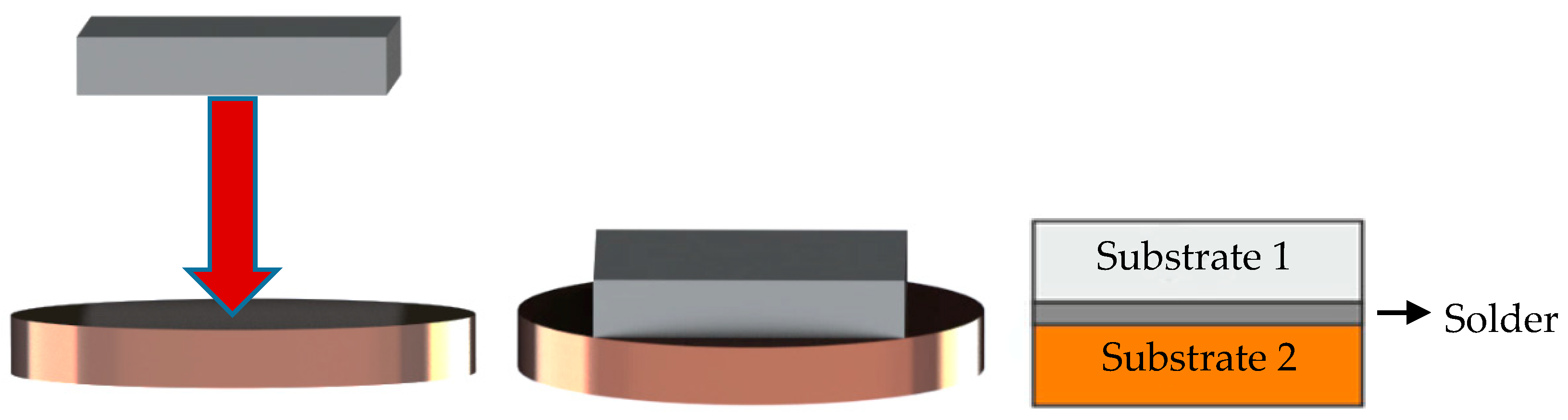
  • Deposition of a small amount of solder with thickness of 600 μm on the surfaces of the substrates;
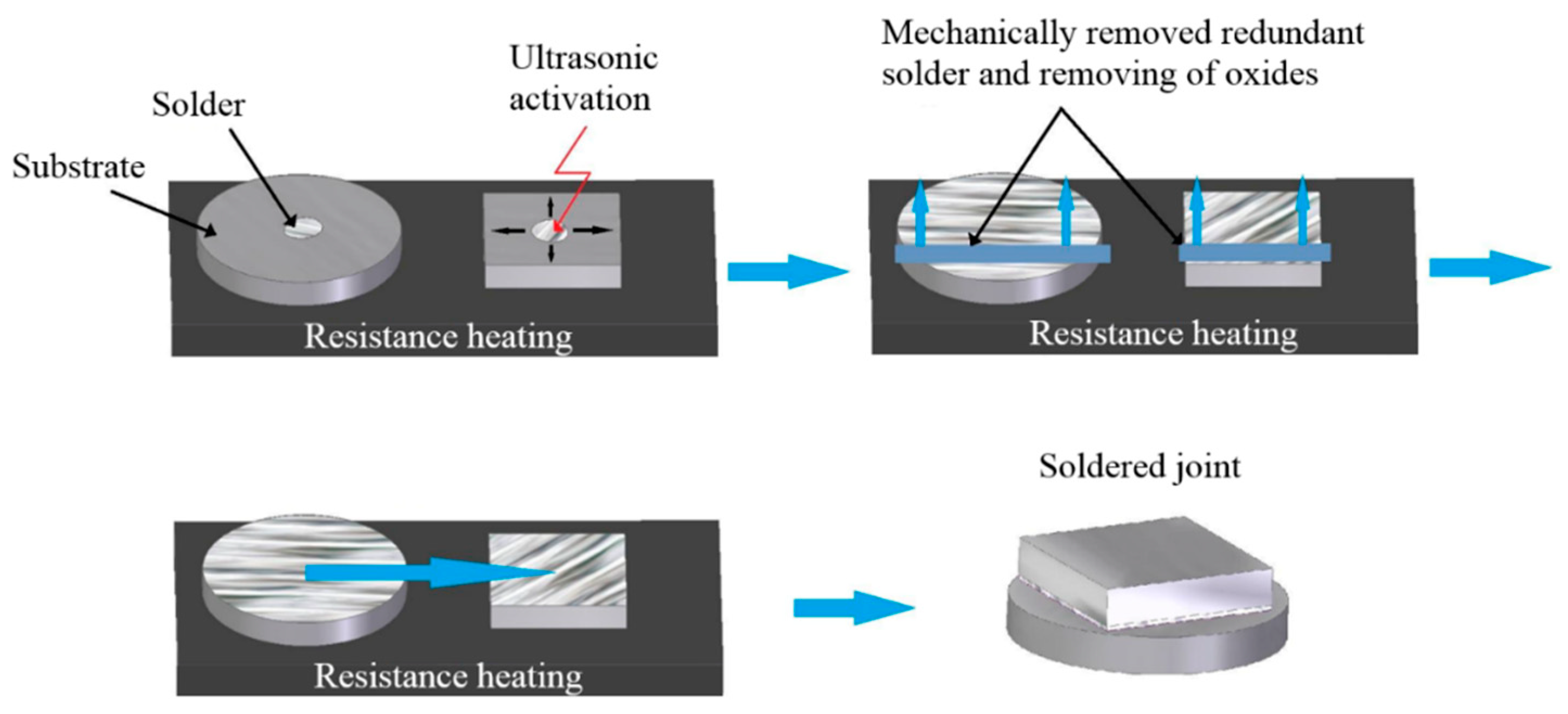
  • Placing the ultrasonic device sonotrode into the molten solder for 5 s;
  • After ultrasound activation, removing the surface oxides on the molten solder by use of a stainless-steel plate;
  • Bringing the prepared substrates with the solder on their surface into contact, and leaving them for approximately 1 min.
A schematic representation of the soldering procedure is shown in Figure 2.
The metallographic preparation consisted of grinding, polishing, and etching the embedded specimens. The specimens were inserted into a jig grinder. Grinding was performed on SiC paper with granularities of 600, 1200, and 2400. During the grinding process, water was supplied to the grinding paper in order to wash away grinding debris. The grinding process on each paper lasted 3 min. After grinding, the polishing process continued on polishing discs with diamond emulsions with particle sizes of 9 μm, 6 μm, 3 μm, and 1 μm. The entire polishing process with all emulsions lasted 4 min.
After polishing, the etching process continued. Nital etchant with a chemical composition of 2 mL of HNO3 and 98 mL of ethanol was applied for 4 s. X-ray diffraction (XRD) analysis was used for the identification of phase composition of the solder and composition on the fractured surfaces after the shear strength test. The X-ray diffraction measurements were carried out using a PANalytical Empyrean diffractometer with Bragg–Brentano geometry (Malvern Panalytical Ltd., Malvern, UK). Characteristic CuKα1,2 (CuKα1 = 1.540598 × 10⁻¹⁰ m, CuKα2 = 1.544426 × 10⁻¹⁰ m) was emitted at an accelerating voltage of 40 kV with a beam current of 40 mA and was collimated using fixed slits. Diffracted radiation was collected using area-sensitive detectors operating in one-dimensional (1D) scanning mode. XRD data were analyzed using the ICSD Inorganic Crystal Structure Database and ICDD PDF2 powder diffraction and crystal structure database.
The differential scanning calorimetry (DSC) analysis was performed on Setaram SETSYS 18TM equipment with a type E DSC sensor. Analysis of alloy specimens was performed in the corundum crucibles with lids in a shielding atmosphere of Ar (6N). The rate of heating and cooling was 5 °C/min. The weight of the analyzed specimens was 40–60 mg. Specimens were, prior to analysis, properly ground and cleaned in acetone with the simultaneous assistance of ultrasound. Prior to analysis proper, the oven space was washed with Ar (6N), and the space around the specimen was subsequently vacuum-pumped and then filled with Ar. A constant dynamic atmosphere of Ar (6N, 2 L/h) was maintained during the entire analysis.
The microstructure of soldering alloy and soldered joints was observed by SEM on an FEI (Field Electron and Ion) Quanta 200 FEG microscope (Scientific and Technical Instruments, Hillsboro, OR, USA).
The solder and soldered joints were studied with the aid of qualitative and quantitative chemical analysis on JOEL 7600 F equipment with a Microspec WDX-3PC microanalyzer (Microspec Corporation, Peterborough, NH, USA).
For the strength measurement of soldered joints, shear strength testing was performed on LabTest 5.250SP1-VM equipment (Labortech Ltd., Prague, Czech Republic). The strength was measured by use of a special jig, for which a schematic representation is shown in Figure 3. The measurement was performed until complete joint failure. The fractured surfaces obtained were assessed by observation of the microstructure, and chemical analysis was performed on JOEL 7600 F equipment (Microspec Corporation, Peterborough, NH, USA).

3. Experimental Results

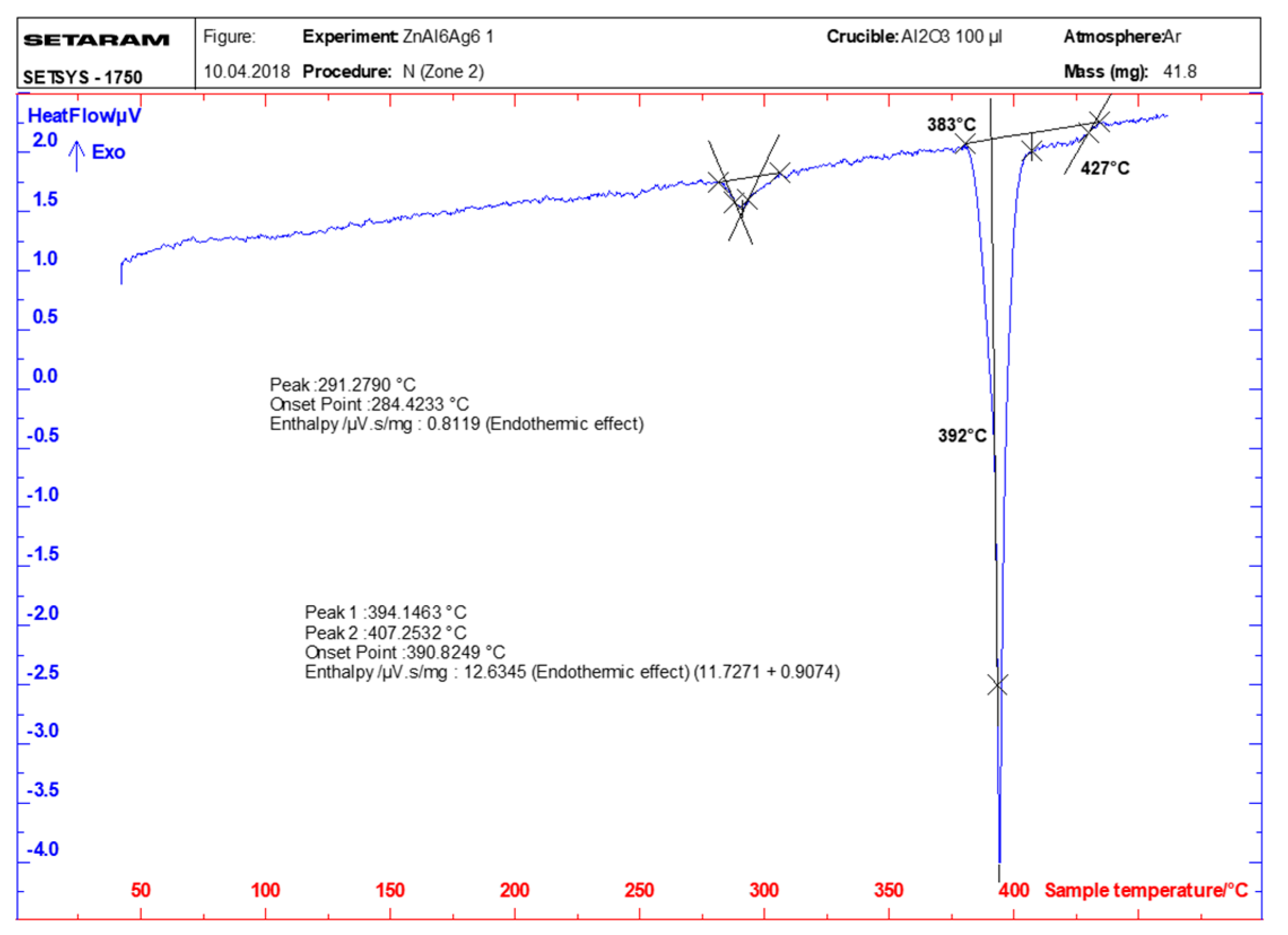
3.1. DSC/DTA Analysis

The DSC/DTA (Differential thermal analysis) analysis was performed on two specimens of soldering alloys. Four temperature changes were observed on both specimens. Table 3 shows the significant temperatures for ZnAl6Ag6 solder, related to a heating rate of 5 °C/min. The TL value is the liquidus temperature. T1 is the temperature of segregation of the AgZn3 phase from the melt. The T2 value is the temperature of eutectic transformation, and T3 is the temperature of eutectoid transformation. Two values mean measurements on two samples.
Figure 4 shows a record from the DSC/DTA analysis, also marking significant temperatures at which the phase transformation in the Zn–Al–Ag system for the given alloy composition took place.
From the isoplethic cross-section shown in Figure 5, valid for 90 wt.% Zn, the sequence of phase formation at cooling from the melt is as follows:
L TL L + AgZn 3 T 1 L + AgZn 3 + ( A L ) T 2 ( AgZn 3 ) + ( A l ) + ( Zn ) T 3 ( AgZn 3 ) + ( Al ) + ( Zn )
The presence of primarily segregated Zn–Ag phase may be expected in alloy structures after total solidification, followed by segregation of Al (Al″), and then solid solution (Zn). The phase (Al″) with high Zn content should be decomposed into a solid solution (Al) with low Zn content under thermodynamic equilibrium conditions below 280 °C.

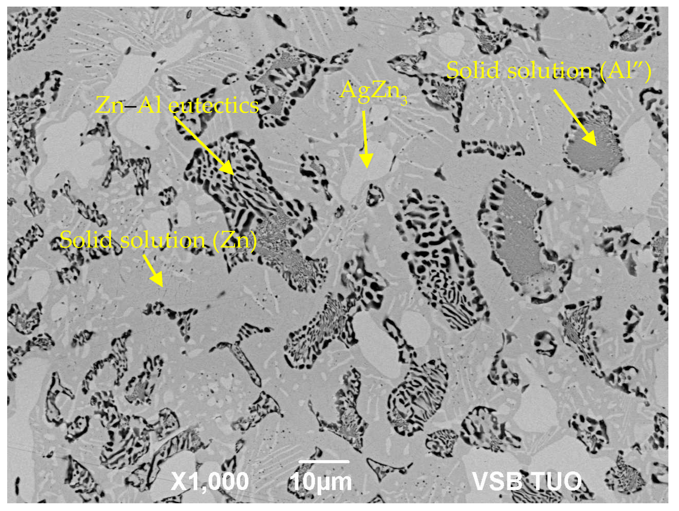
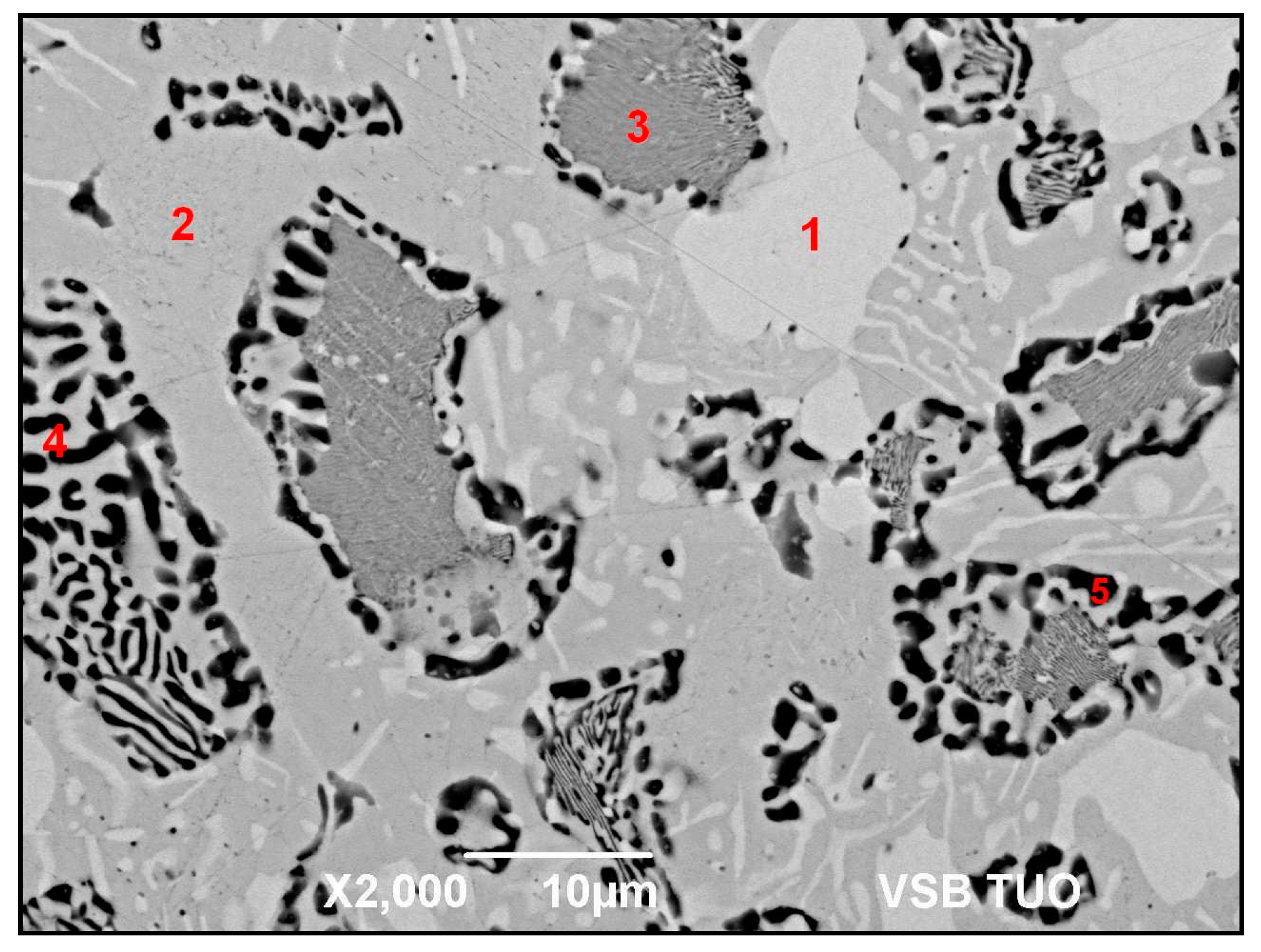
3.2. Microstructure of Zn–Al–Ag Solder

The microstructure of Zn6Al6Ag solder is shown in Figure 6. This microstructure was observed by SEM microscopy in BSE (Back-scattered electrons) study mode. In BSE mode, the measure of darkening is indirectly proportional to the average atomic mass of elements present at the given point (lighter elements are presented as darker, e.g., the solid solution (Al), while heavier elements are presented as brighter, e.g., the solid solution (Zn) and AgZn3 phase).
To determine the chemical composition of the individual components of soldering alloys, local chemical EDX (Energy-dispersive X-ray spectroscopy) microanalysis was performed. The points where the analysis was executed are marked by the numerals in Figure 7 and Table 4, while the results of phase composition are shown in the table under the figure. Spectrum 1 shows the light-gray phase containing the ε phase with 78 wt. % Zn and 22 wt. % Ag without the presence of Al. In accordance with the phase diagram for Ag–Zn (Figure 5), this phase is stable over a wide range of concentrations. The phase may be designated as Ag0.26Zn0.74 or AgZn3. Spectrum 2 shows a medium-gray matrix. It is formed of a zinc solid solution, with dissolved Ag in amounts from 1.3 to 4.5 wt.%, which correspond to the binary diagram (Ag–Zn). Spectrum 3 shows a dark-gray zone, containing the solid solution (Al″) with high Zn content. This phase was formed by a eutectic reaction at a temperature of approximately 380 °C. The Ag presence is minimal here. Spectrum 4 shows a zone formed of eutectic with high Al content (around 31 wt.%) and Zn (around 71 wt.%). Ag content occurred here at the level of 2 wt.%.
Spectrum 5 shows a dark zone detected in eutectic, which proved the presence of solid solution (Al) with considerably lower Zn content than in Spectrum 3.
To confirm and clearly identify phases in the soldering alloy, XRD analysis was performed. The diffraction record of Zn6Al6Ag solder is shown in Figure 8. The record identified Zn that occurred in the form of a βZn solid solution in solder bulk. The analysis also identified the presence of Al and AgZn3 intermetallic phases. The XRD record proves that a wide proportion of this phase was found in solder bulk.

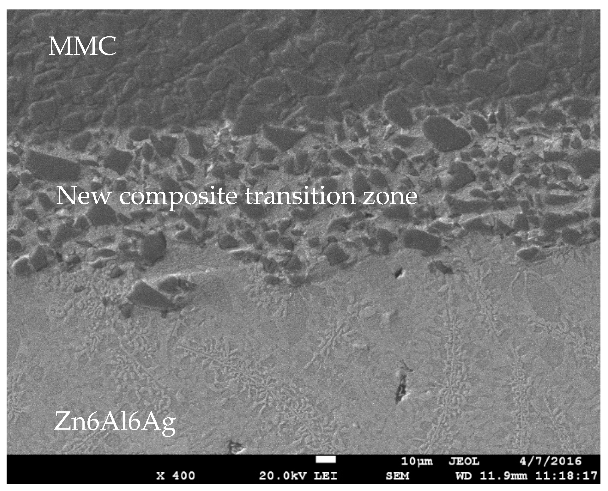
3.3. Analysis of Soldered Joint on the Boundary of MMC/Zn6Al6Ag Joint

The microstructure of the boundary of the MMC/Zn6Al6Ag soldered joint is shown in Figure 9. In soldering the composite materials of Al/Al2O3 with Zn6Al6Ag, a significant dissolution of aluminum from the composite occurred and, thus, a transition zone over a span of up to 75 μm also formed. Movement of the Al2O3 particles also took place in this zone. The volume fraction of ceramic particles in the new composite transition zone were reduced approximately by half.
The bond between the ceramic composite and Zn6Al6Ag solder was formed as follows: the surface oxides on the MMC substrate were firstly disrupted under the molten layer of Zn solder under fluxless soldering in air. Subsequently, dissolution of the aluminum surface of the MMC substrate took place due to the action of molten Zn solder. Through the dissolution of the aluminum matrix of the substrate, the Al2O3 particles, which were initially in the MMC substrate, were also put into motion. The transition zone or solubility band was, thus, formed.
EDX point microanalysis was performed in the transition zone. The results of the point analysis are shown in Figure 10 and Table 5. Measurement was performed at individual points (spectra). From the results of the analysis given in Table 5 under Figure 10, it is obvious that mainly the solid solution (Al) Spectra 1 and 3 occurred in the transition zone.
High-wt.% Al was recorded in both measured spectra, but not in Spectrum 2. From the measurement performed at the point labeled Spectrum 2, the presence of silver was identified in the form of ε–AgZn3 phase. The results of point analysis suggest that the initial grains of the Al/Al2O3 composite were wetted with the new alloy formed of Zn and Ag elements and dissolved Al. The map of individual elements, partially in the transition zone and partially in the solder, is documented in Figure 11.
It is also obvious here that Zn and Al occurred in the transition zone, with non-uniformly distributed Ag. Zn mainly contributed to the formation of a bond between the ceramic composite and Zn solder, but the presence of silver in the transition zone of the bond was also confirmed.

3.4. Analysis of Soldered Bond in the Boundary of Al2O3/Zn6Al6Ag Joint

The microstructure of the transition zone in the Al2O3/Zn6Al6Ag joint is documented in Figure 12. The microstructure shows the surface of the Al2O3 ceramic substrate, which was coarsened by ultrasound assistance. The penetration of solder into the depressions and voids in the ceramic is clearly visible, as well as the wetting of ceramic material with Zn6Al6Ag solder.
The bond with ceramic material was formed as follows: firstly, the surface of the ceramic was disrupted by ultrasound assistance during the soldering process. Portions of zinc and aluminum were oxidized during soldering in air. The oxidized zinc particles were distributed to the boundary with ceramic material, owing to ultrasonic activation. The zinc particles combined with oxides on the surface of the ceramic material, which resulted in wetting and solder penetration into depressions and voids on the substrate surface.
The point EDX analysis of a depression in the Al2O3 substrate with a width of 5 µm is documented in Figure 13 and Table 6. It shows that mainly Zn and Al, as well as partially Ag in the form of oxides, contributed to bond formation at the surface of the Al2O3 ceramic. The points of measurement (Figure 13) in the depressions in Al2O3 ceramic are marked as Spectra 1 to 3. The Zn content was observed from 69.18 to 80.14 wt.%, and the aluminum content was observed from 11.77 to 27.77 wt.%.

3.5. Measurement of Shear Strength in Soldered Joints

The research in this study was primarily oriented toward soldering the substrate made of MMC composite with Al2O3. Owing to a comparison of the results, a measurement of shear strength was also performed with the MMC/Al7075 (AlZn5.5MgCu) combination, followed by the MMC/Cu and Al2O3/Al2O3 combinations. The measurement was performed on four specimens of each material. The results for the average shear strength of joints are documented in Figure 14.
The lowest average shear strength of 23 MPa was obtained with the MMC/Al2O3 combination. In the case of the Al2O3/Al2O3 combination, a higher average shear strength of 44 MPa was observed. Considerably higher shear strength values of 127.5 and 139.5 MPa, respectively, were observed with the MMC/7075 and MMC/Cu soldered joints.
The large differences in the shear strength of MMC/Al2O3, MMC/Al7075, and MMC/Cu joints may be explained by the different mechanisms of bond formation. In the case of MMC and Al7075 materials, the bond is formed by the dissolution of Zn in solder.
Similarly, in the case of copper substrate, the bond is formed by dissolution of the Cu substrate in Zn solder during the formation of the new intermetallic phases. However, in the case of soldering Al2O3 ceramics, no new phase is formed at the ceramic/solder boundary, and diffusion does not take place; therefore, the bond is simply of adhesive character.
Moreover, in soldering the Al2O3/Al2O3 combination, the CTE was the same, and that is why no significant residual stresses were formed, which resulted in higher shear strength compared with the MMC/Al2O3 combination.

3.6. Analysis of Fractured Surfaces

The fractured surfaces of joints were analyzed for more precise identification. Figure 15a shows the documented fractured surface at the boundary of the Al2O3/Zn6Al6Ag joint. We can see that the fractured surface of the Al2O3 substrate remained partially covered with solder. An analysis of the planar distribution of Zn, Al, Ag, and O elements on the fractured surface was performed, as documented in Figure 15b–e. The ceramic substrate represents mainly Al and O elements. The solder is best depicted by Zn and Ag elements.
XRD analysis was performed at the boundary of the Al2O3/Zn6Al6Ag joint. Two majority phases were identified as solid solution (Al) and solid solution (Zn), as well as Al2O3 oxide, which was probably part of the substrate. Several components of the solder oxidized during soldering in air and, therefore, the presence of the AgAlO oxide phase was also confirmed. The record from the XRD analysis is documented in Figure 16.

4. Conclusions

The aim of this research was to study the Zn6Al6Ag soldering alloy and its application for ultrasonic soldering of an Al2O3/composite (Al/Al2O3) combination. It was determined whether the proposed composition would be suitable for soldering ofAl2O3 ceramic and a metal–ceramic substrate (Al/Al2O3) under the defined conditions. The following results were obtained:
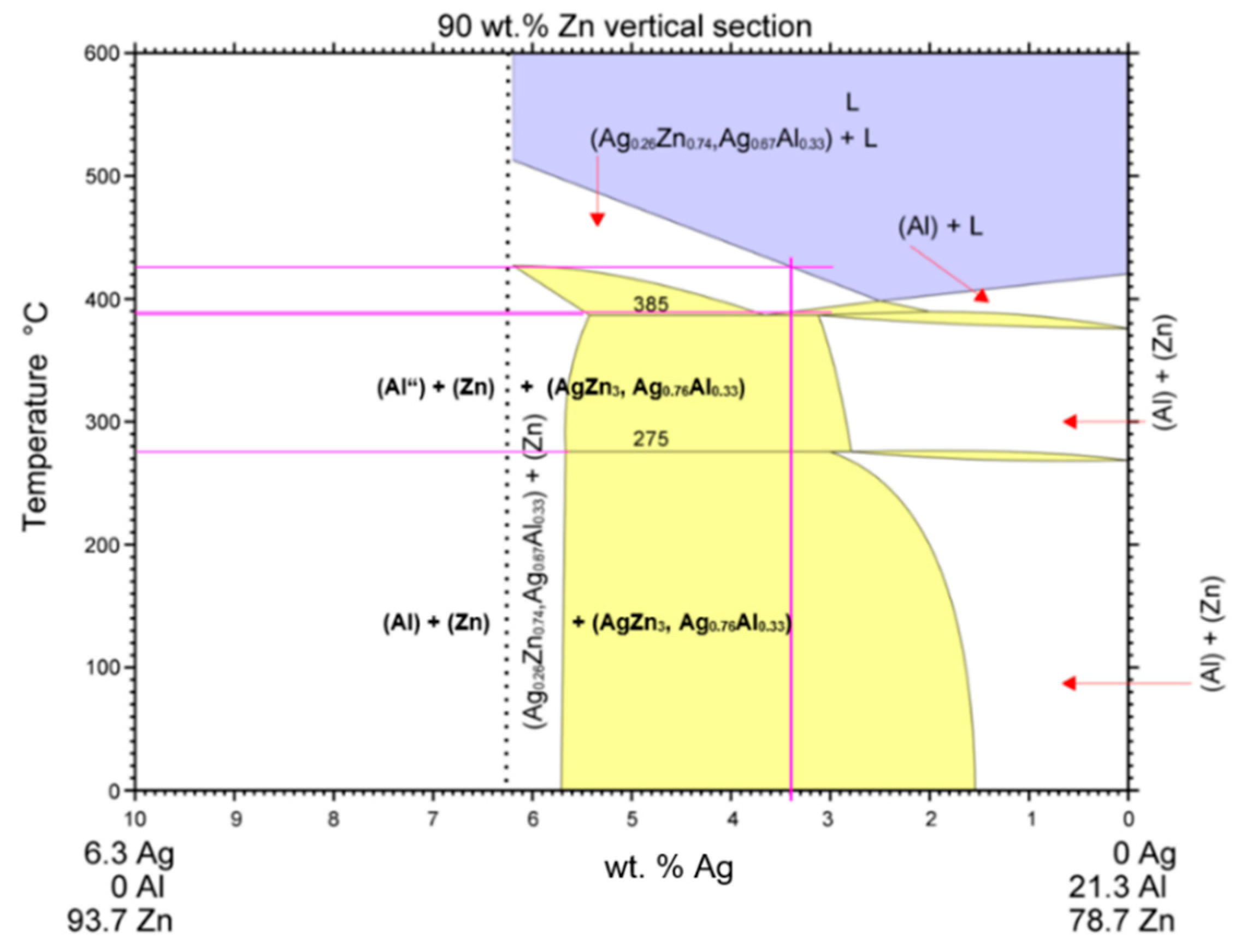
  • DSC analysis was used to determine the melting point of the solder. The DSC curve contained two main peaks with four thermal effects in the Zn–Al–Ag system. The first and smaller peak corresponded to the eutectoid reaction at a characteristic temperature of 275 °C. The second and larger peak corresponded to a eutectic reaction at the characteristic temperature of 385 °C. Next, the reaction at a temperature of 405 °C corresponded to segregation of the AgZn3 phase. The last reaction characterized the melting point of solder at a temperature of 427 °C.
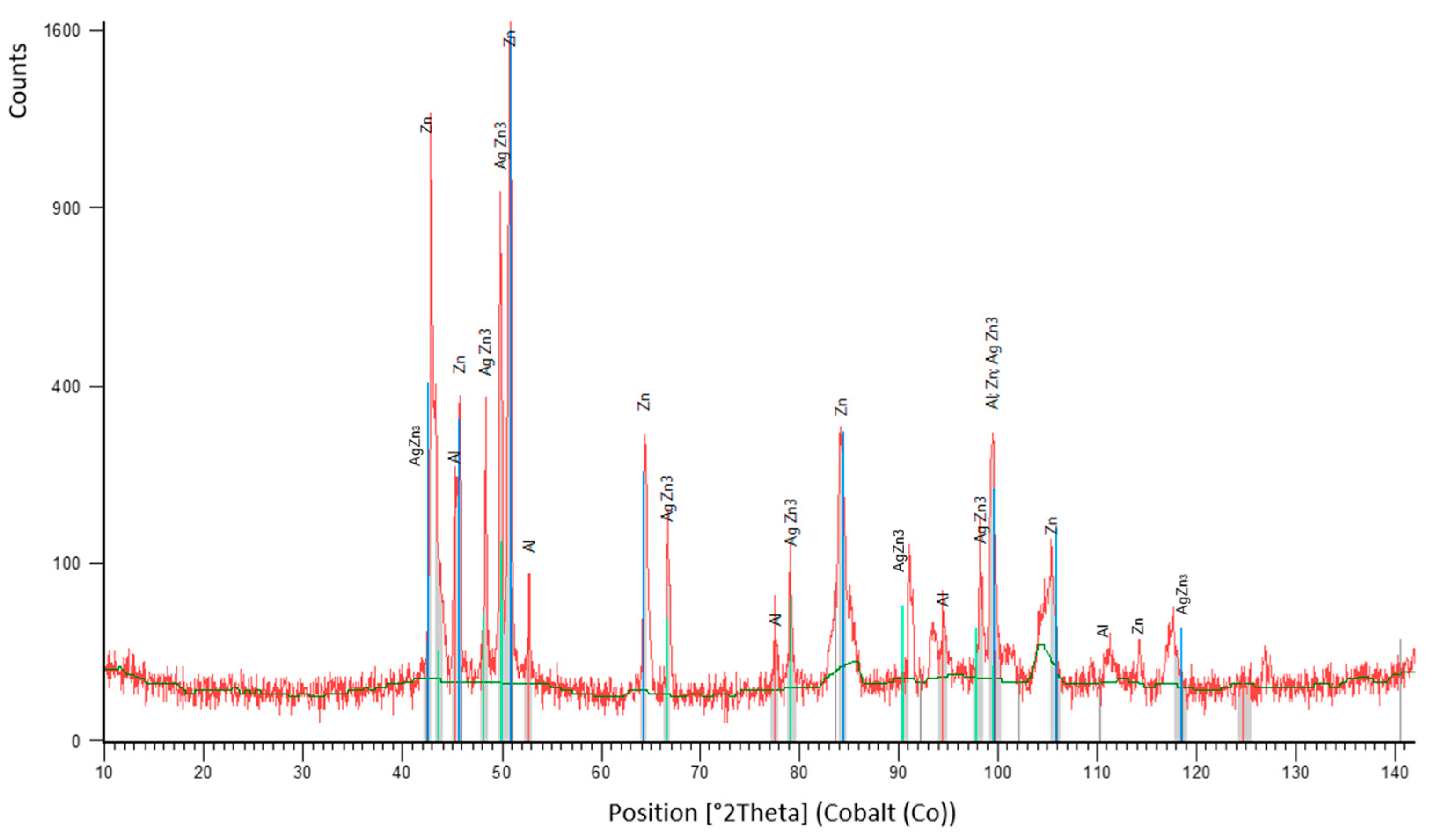
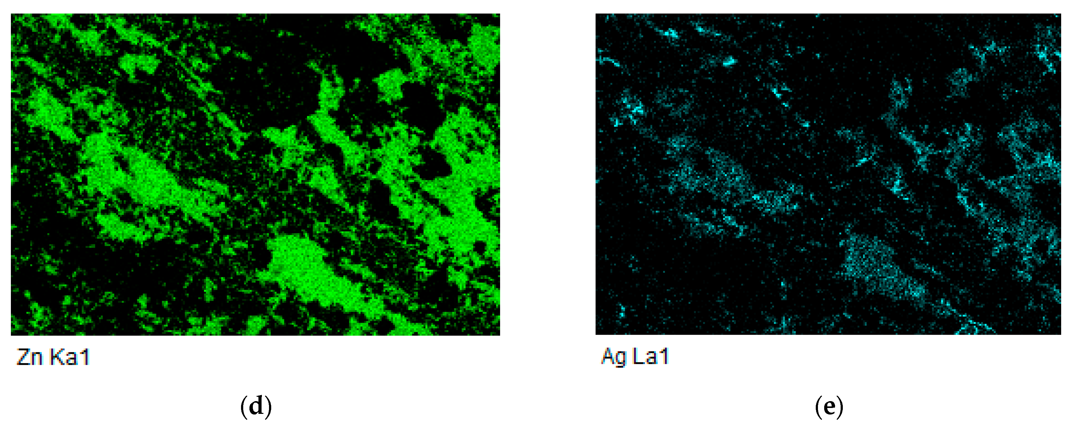
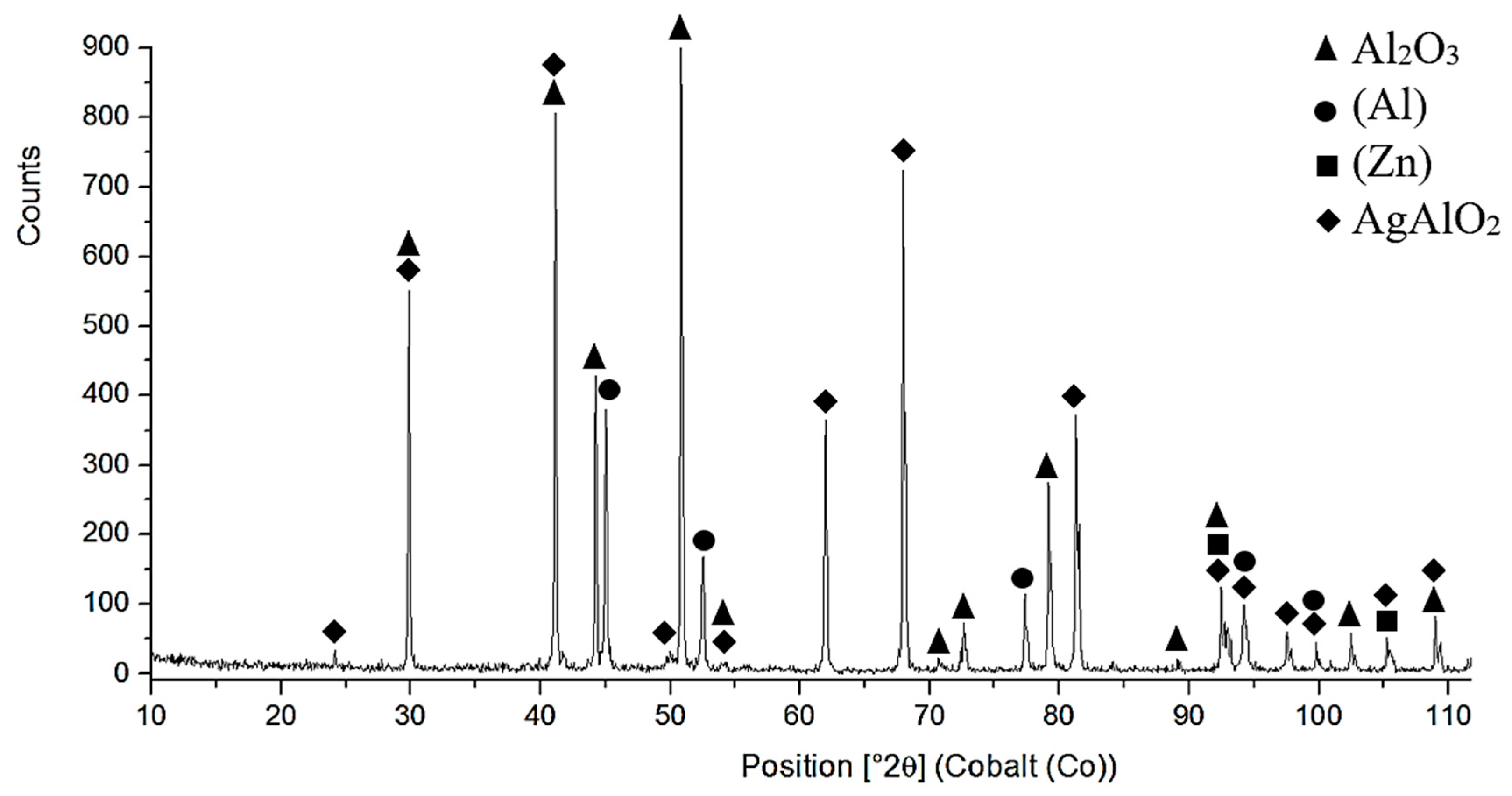
  • The microstructure of Zn6Al6Ag solder consisted of solid solution (Al), solid solution (Zn), and ε–AgZn3 phase, which was proven by EDX and XRD analyses.
  • The bond between the ceramic composite and Zn6Al6Ag solder was formed as follows: firstly, the surface oxides on the MMC substrate were disrupted under the molten layer of zinc solder. Subsequently, the dissolution of the aluminum surface of the MMC substrate took place, owing to the activity of the molten Zn solder. On dissolution of the aluminum matrix of the substrate in the zinc solder, the Al2O3 particles, which were initially in the MMC substrate, were also put into motion. A transition zone was, thus, formed (a band formed of a new composite).
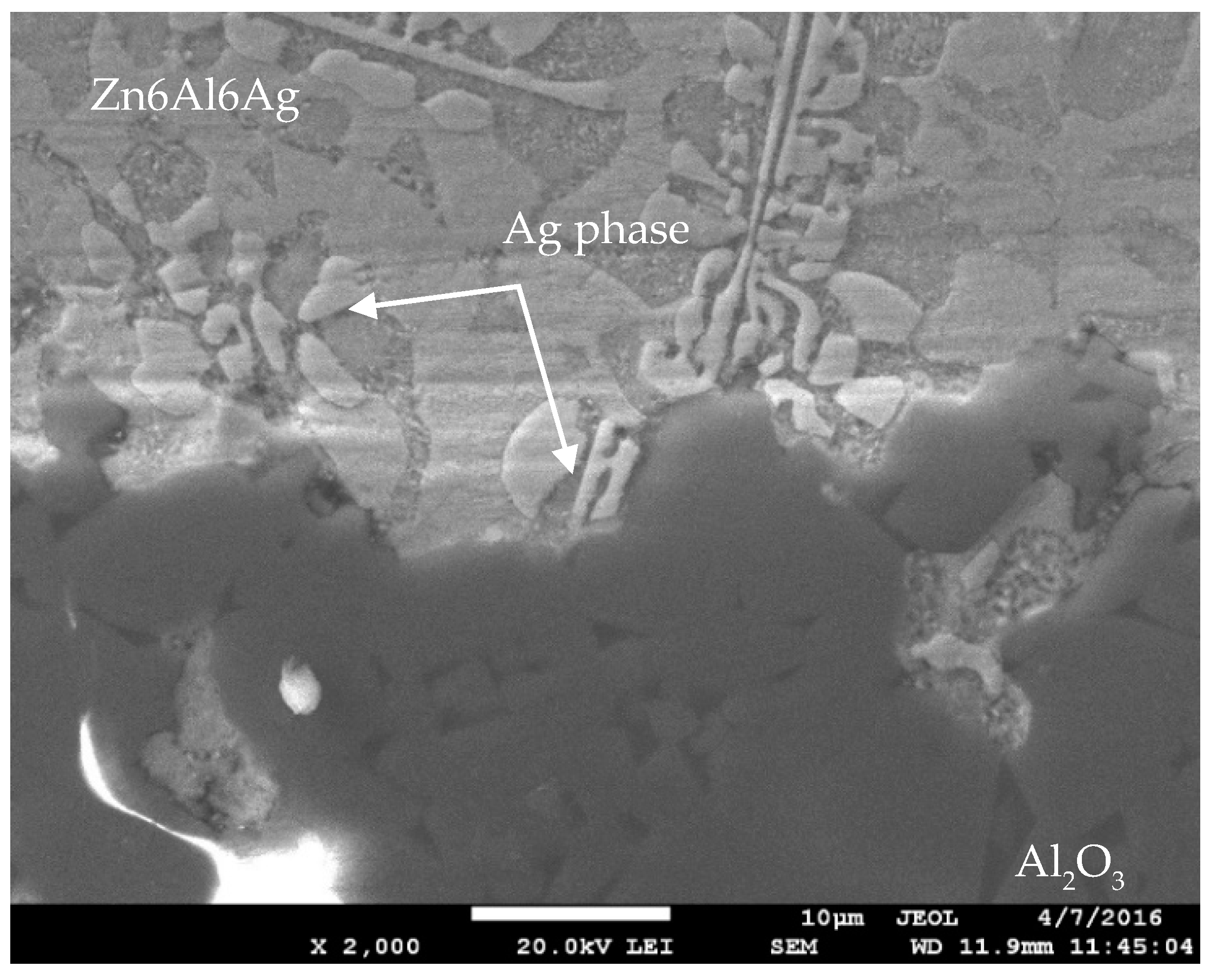
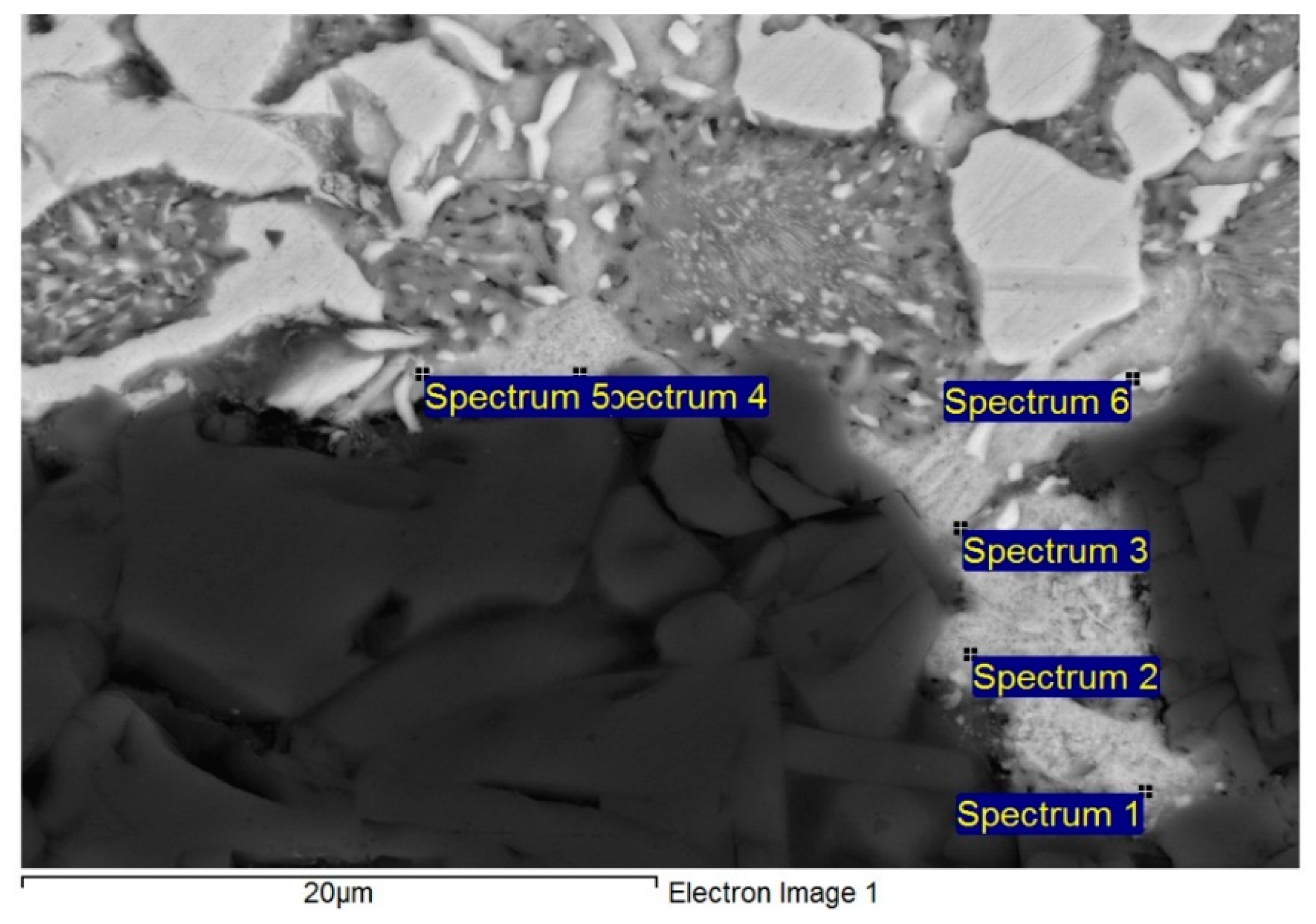
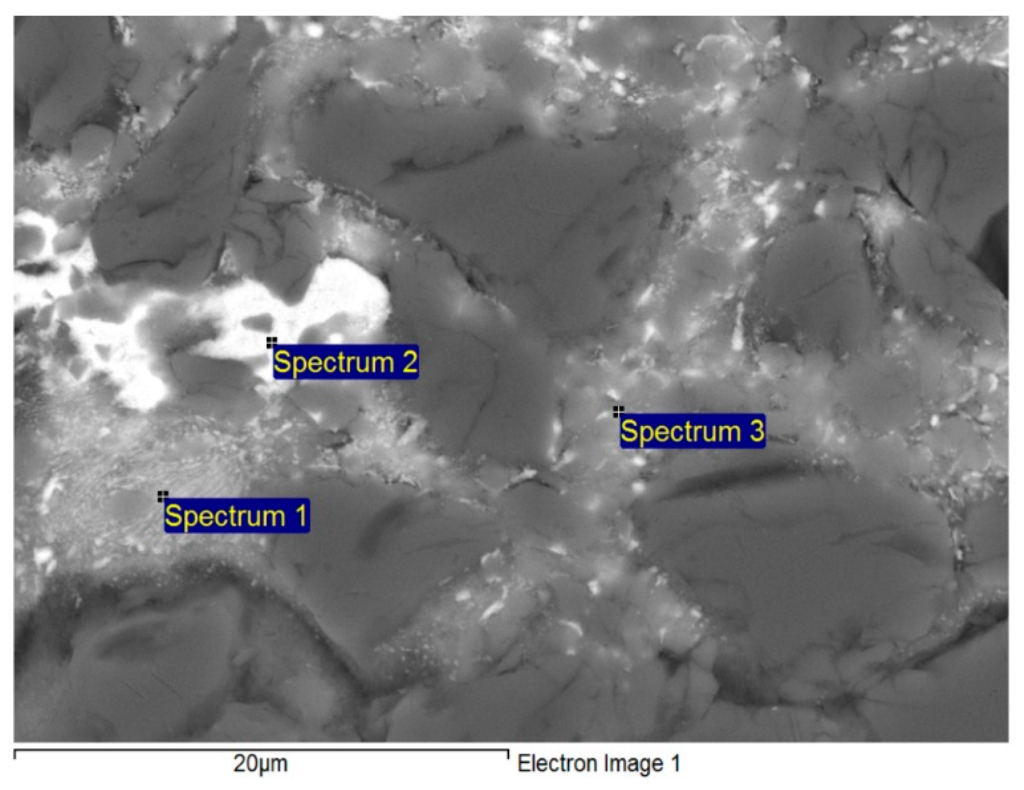
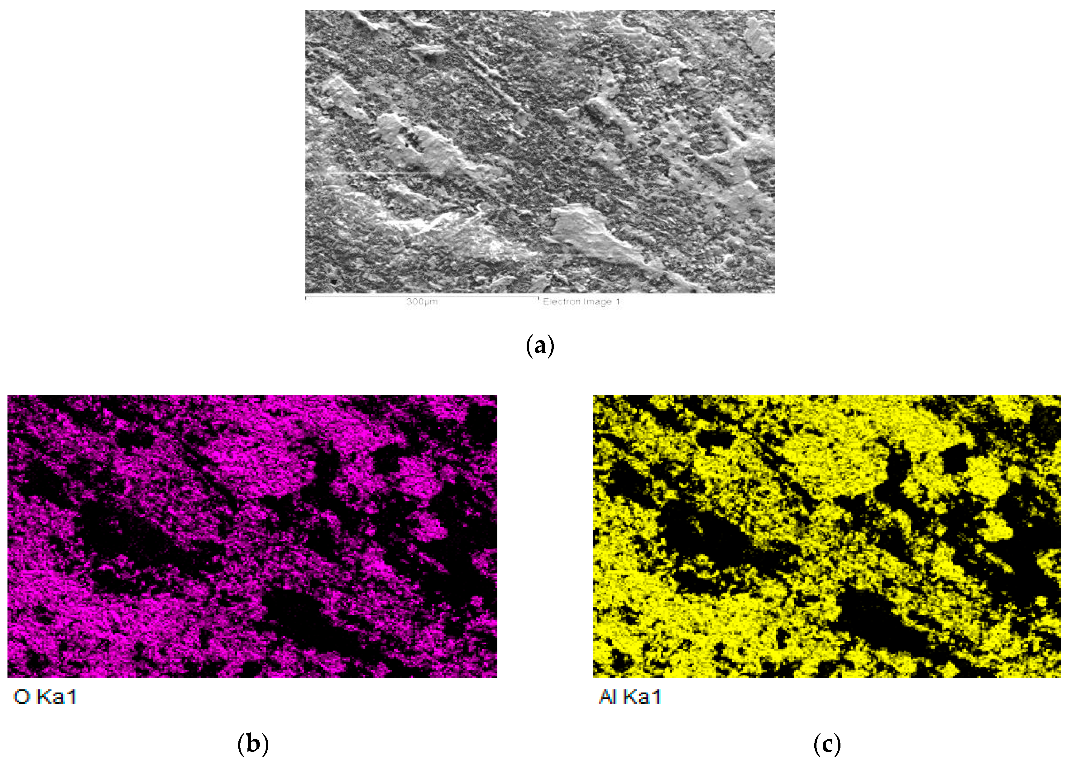
  • The bond of Al2O3 with Zn6Al6Ag solder was formed as follows: in soldering with ultrasound assistance, the surface of the ceramic was firstly disrupted. Portions of Zn and Al were oxidized during soldering in air. Owing to ultrasound activation, the oxidized Zn and Al particles were distributed to the boundary of the ceramic material. The Zn, Al, and Ag particles combined with the oxides on the surfaces of ceramic materials, resulting in wetting and penetration of solder into the recesses on the substrate surfaces.
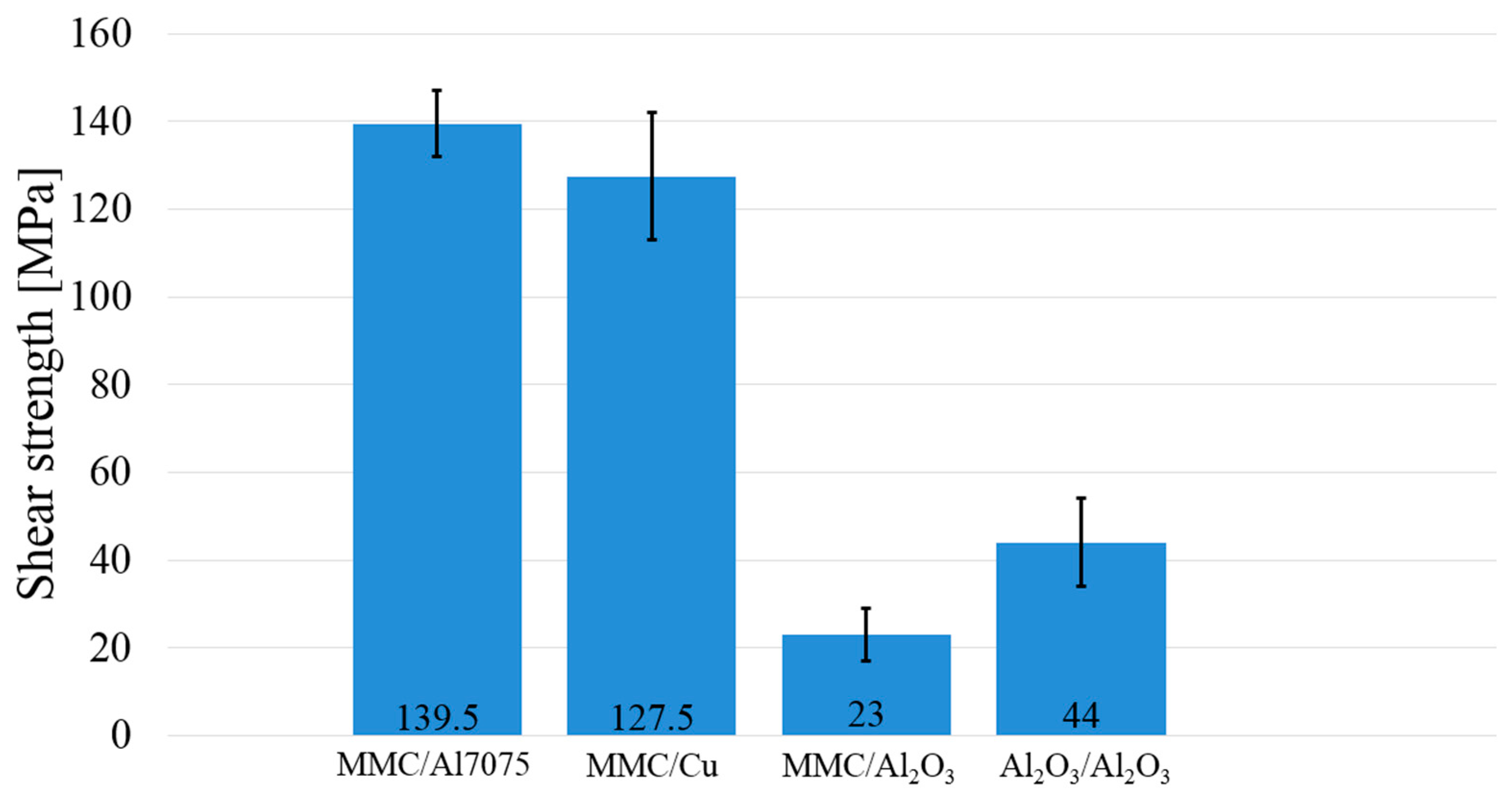
  • In the case of the MMC/Al2O3 combination, the average shear strength attained was 23 MPa. In the case of soldering Al2O3 ceramics, no new phase at the ceramic/solder boundary was formed, and diffusion did not take place; therefore, the bond was merely of an adhesive character.

Author Contributions

Supervision, R.K.; Investigation, I.K.; Formal analysis, J.D. and P.B.; Data curation, M.P. All authors have read and agreed to the published version of the manuscript.

Funding

This research was funded by Slovak Research and Development Agency under contract no. APVV-17-0025; Slovak Scientific Grant Agency VEGA under contract no. VEGA 1/0303/20; Project 1393 – Soldering – Excellent teams and Project Young Researcher excellent teams no. 1392

Acknowledgments

The paper was also prepared in cooperation with the VSB Technical University of Ostrava, FMT Faculty of Materials Science and Technology, Department of Non-Ferrous Metals, Refining, and Recycling.

Conflicts of Interest

The authors declare no conflict of interest.

References

  1. Kaczmar, J.W.; Pietrzak, K.; Włosiński, W. The production and application of metal matrix composite materials. J. Mater. Process. Technol. 2000, 106, 58–67. [Google Scholar] [CrossRef]
  2. Mallik, S.; Ekere, N.; Best, C.; Bhatti, R. Investigation of thermal management materials for automotive electronic control units. Appl. Therm. Eng. 2011, 31, 355–362. [Google Scholar] [CrossRef] [Green Version]
  3. Zweben, C. Metal-matrix composites for electronic packaging. JOM 1992, 44, 15–23. [Google Scholar] [CrossRef]
  4. Kim, J.H.; Jeong, S.W.; Lee, H.M. Thermodynamics aided alloy design and evaluation of Pb-free solders for high-temperature applications. Mater. Trans. 2002, 43, 1873–1878. [Google Scholar] [CrossRef] [Green Version]
  5. Chidambaram, V.; Hald, J.; Hattel, J. Development of Au-Ge based candidate alloys as an alternative to high-lead content solders. J. Alloys Compd. 2010, 490, 170–179. [Google Scholar] [CrossRef]
  6. Kroupa, A.; Andersson, D.; Hoo, N.; Pearce, J.; Watson, A.; Dinsdale, A.; Mucklejohn, S. Current Problems and Possible Solutions in High-Temperature Lead-Free Soldering. J. Mater. Eng. Perform. 2011, 21, 629–637. [Google Scholar] [CrossRef]
  7. Rettenmayr, M.; Lambracht, P.; Kempf, B.; Graff, M. High melting Pb-free solder alloys for die-attach applications. Adv. Eng. Mater. 2005, 7, 965–969. [Google Scholar] [CrossRef]
  8. Suganuma, K.; Kim, S.J.; Kim, K.S. High-Tepmerature Lead-Free Solders: Properties and Possibilities. JOM 2009, 61, 64–71. [Google Scholar] [CrossRef]
  9. Cay, F.; Kurnaz, C. Hot tensile and fatigue of zinc-aluminium alloys produced by gravity and squeeze casting. Mater. Des. 2005, 26, 479–485. [Google Scholar] [CrossRef]
  10. Prach, M.; Kolenak, R. Soldering of Copper with High-Temperature Zn-Based Solders. Proceeding of the 25th DAAAM International Symposium on Intelligent Manufacturing and Automation, Vienna, Austria, 26–29 November 2014; pp. 1370–1375. [Google Scholar]
  11. Haque, A.; Lim, B.H.; Haseeb, A.S.M.A.; Masjuki, H.H. Die attach properties of Zn-Al-Mg-Ga based high-temperature lead-free solder on Cu lead-frame. J. Mater. Sci. Mater. Electron. 2012, 23, 115–123. [Google Scholar] [CrossRef]
  12. Cheng, F.; Gao, F.; Wang, Y.; Wu, Y.; Ma, Z.; Yang, J. Sn addition on the tensile properties of high temperature Zn-4Al-3Mg solder alloys. Microelectron. Reliab. 2012, 52, 579–584. [Google Scholar] [CrossRef]
  13. Shimizu, T.; Ishikawa, H.; Ohnuma, I.; Ishida, K. Zn-Al-Mg-Ga Alloys as Pb-Free Solder for Die-Attaching Use. J. Electron. Mater. 1999, 28, 1172–1175. [Google Scholar] [CrossRef]
  14. Chen, X.; Yan, J.; Ren, S.; Wang, Q.; Wei, J.; Fan, G. Microstructure, mechanical properties, and bonding mechanism of ultrasonic-assisted brazed joints of SiC ceramics with ZnAlMg filler metals in air. Ceram. Int. 2014, 40, 683–689. [Google Scholar] [CrossRef]
  15. Zhang, Y.; Yan, J.; Chen, X.; Cui, Y. Ultrasonic dissolution of brazing of 55% SiCp/A356 composites. Trans. Nonferrous Met. Soc. China 2010, 20, 746–750. [Google Scholar] [CrossRef]
  16. Jinbin, L.; Yunchao, M.; Xiangwei, L.; Jintal, N. A New Method For Soldering Particle-reinforced aluminum metal matrix composites. Mater. Sci. Eng., B 2012, 177, 1759–1763. [Google Scholar]
  17. Gancarz, T.; Pstruś, J.; Fima, P.; Mosinska, S. Thermal properties and wetting behavior of high temperature Zn-Al-In solders. J. Mater. Eng. Perform. 2012, 21, 599–605. [Google Scholar] [CrossRef] [Green Version]
  18. Li, Y.; Zhao, W.; Leng, X.; Fu, Q.; Wang, L.; Yan, J. Microstructure evolution and mechanical properties of ultrasonic-assisted soldering of 2024 aluminum alloys. Trans. Nonferrous Met. Soc. China 2011, 21, 1937–1943. [Google Scholar] [CrossRef]
  19. Wang, Z.; Wang, H.; Liu, L. Study of low temperature brazing of magnesium alloy to aluminum alloy using Sn-xZn solders. Mater. Des. 2012, 39, 14–19. [Google Scholar] [CrossRef]
  20. Xiao, Z.; Ji, H.; Li, M.; Kim, J. Ultrasound-assisted brazing of Cu/Al dissimilar metals using a Zn-3Al filler metal. Mater. Des. 2013, 52, 740–747. [Google Scholar] [CrossRef]
  21. Zhang, L.X.; Shi, J.M.; Li, H.W.; Tian, X.Y.; Feng, J.C. Interfacial microstructure and mechanical properties of ZrB2-SiC-C ceramic and GH99 superalloy joints brazed with a Ti-modified FeCoNiCrCu high-entropy alloy. Mater. Des. 2016, 97, 230–238. [Google Scholar] [CrossRef]
  22. Chen, B.; Xiong, H.; Cheng, Y.; Mao, W.; Wu, S. Microstructure and property of AlN joint brazed with Au-Pd-Co-Ni-V brazing filler. J. Mater. Sci. Technol. 2015, 31, 1034–1038. [Google Scholar] [CrossRef]
  23. Ghosh, S.; Chakraborty, R.; Dandapat, N.; Pal, K.S.; Datta, S.; Basu, D. Characterization of alumina–alumina/graphite/monel superalloy brazed joints. Ceram. Int. 2012, 38, 663–670. [Google Scholar] [CrossRef]
  24. Guo, W.; Zhu, Y.; Wang, L.; Qu, P.; Kang, H.; Chu, P.K. Microstructure evolution and mechanical properties of vacuum-brazed C/C composite with AgCuTi foil. Mater. Sci. Eng., A 2013, 564, 192–198. [Google Scholar] [CrossRef]
  25. Shi, J.M.; Feng, J.C.; Liu, H.; Tian, X.Y.; Zhang, L.X. Vacuum brazing of the Gr/2024Al composite and TC4 alloy using AgCuTi filler alloy with Ni-Al interlayer as auxiliary heat source. J. Alloys Compd. 2017, 694, 672–681. [Google Scholar] [CrossRef]
  26. Massalski, T.B.; Okamoto, H. Binary Alloy Phase Diagrams; ASM International: Materials Park, OH, USA, 1990. [Google Scholar]
Figure 1. Schematic representation of setup of soldered materials.
Metals 10 00343 g001
Figure 2. Soldering procedure.
Metals 10 00343 g002
Figure 3. Schematic representation of the jig for shear strength measurement.
Metals 10 00343 g003
Figure 4. DTA record for the ZnAl6Ag6 alloy at a heating rate of 5 °C/min.
Metals 10 00343 g004
Figure 5. Isoplethic cross-section through the ternary system of Ag–Al–Zn for 90 wt.% Zn [26].
Metals 10 00343 g005
Figure 6. Microstructure of Zn6Al6Ag solder.
Metals 10 00343 g006
Figure 7. EDX analysis of soldering alloy type Zn–Al–Ag.
Metals 10 00343 g007
Figure 8. The X-ray diffraction (XRD) record of Zn6Al6Ag solder.
Metals 10 00343 g008
Figure 9. Microstructure of boundary in the metal–ceramic composite (MMC)/Zn6Al6Ag joint.
Metals 10 00343 g009
Figure 10. EDX point analysis of bond in the boundary of MMC/Zn6Al6Ag joint, the zone with a new composite.
Metals 10 00343 g010
Figure 11. Planar distribution of elements in the boundary of MMC/Zn6Al6Ag soldered joint.
Metals 10 00343 g011
Figure 12. Microstructure of transition zone in Al2O3/Zn6Al6Ag joint.
Metals 10 00343 g012
Figure 13. Point EDX analysis of boundary in Al2O3/Zn6Al6Ag joint.
Metals 10 00343 g013
Figure 14. Measurement of shear strength of the joints fabricated with Zn6Al6Ag solder.
Metals 10 00343 g014
Figure 15. Planar analysis of elements on the fractured surface of Al2O3/Zn6Al6Ag joint: (a) fracture morphology; elements (b) O, (c) Al, (d) Zn, and (e) Ag.
Metals 10 00343 g015aMetals 10 00343 g015b
Figure 16. XRD analysis of fractured surface of Al2O3/Zn6Al6Ag joint.
Metals 10 00343 g016
Table 1. Composition of Zn–Al–Ag alloys and the results of chemical analysis done using the induction-coupled plasma atomic emission spectrometry (ICP-AES) method (wt.%).
SpecimenCharge (wt.%)ICP-AES (wt.%)
ZnAlAgZnAlAg
Zn6Al6Ag88.06.06.088.386.14 ± 0.315.48 ± 0.55
Table 2. Soldering parameters.
ParametersUnitValue
Ultrasound PowerW400
Working frequencykHz40
Amplitudeμm2
Soldering temperature°C430
Time of ultrasound activations5
Table 3. The temperatures of phase transformation under heating in accordance with DSC/DTA analysis.
AlloyHeat
TLT1T2T3
ZnAl6Ag6427406391285
424405385280
Table 4. The phase composition results of Zn-Al-Ag solder.
Spectrum.Zn (wt.%)Al (wt.%)Ag (wt.%)Solder Component
Spectrum 178.2-21.8phase AgZn3
Spectrum 298.7-1.3solid solution (Zn)
Spectrum 377.220.91.9solid solution (Al″)
Spectrum 463.635.50.9Zn–Al eutectic
Spectrum 541.658.10.3solid solution (Al″)
Table 5. The phase composition of MMC/Zn6Al6Ag joint boundary.
SpectrumZn (wt.%)Al (wt.%)Ag (wt.%)Solder Component
Spectrum 147.9344.807.26phase (Al)
Spectrum 276.285.0718.65Phase ε–AgZn3
Spectrum 348.2348.233.54phase (Al)
Table 6. The phase composition of Al2O3/Zn6Al6Ag joint boundary.
Spectrum.Zn (wt.%)Al (wt.%)Ag (wt.%)O (wt.%)
Spectrum 172.179.907.0410.89
Spectrum 273.7610.835.759.66
Spectrum 364.9525.202.807.04
Spectrum 469.0214.642.8413.51
Spectrum 562.0225.694.238.06
Spectrum 657.4214.8011.5116.27

