Article

Study on Grinding and Deformation Fracture Control of Cold Rolled Titanium Strip

1
Institute of Engineering Technology, University of Science and Technology Beijing, Beijing 100083, China
2
Collaborative Innovation Center of Steel Technology, University of Science and Technology Beijing, Beijing 100083, China
3
School of Materials Science and Engineering, University of Science and Technology Beijing, Beijing 100083, China
*
Authors to whom correspondence should be addressed.
Metals 2020, 10(3), 323; https://doi.org/10.3390/met10030323
Submission received: 11 January 2020 / Revised: 24 February 2020 / Accepted: 26 February 2020 / Published: 29 February 2020
(This article belongs to the Special Issue Rolling of Metals)

Abstract

:
Surface defects of titanium strip need to be removed by local grinding, but local cracking or band breaking then occurs during subsequent cold rolling. Tensile properties and deformation resistance of 3 mm thick commercially pure titanium strip with grinding pits on the surface were simulated by a finite-element method using a multi-pass cold-rolling deformation process. The stress and strain of grinding pits with depths of 0.25–2 mm were analyzed. During cold-rolling deformation, the stress and strain in the center of a grinding pit were larger than at the edge region. The strip was first subjected to tensile stress in the rolling direction, which then decreased and gradually changed to compressive stress. Partial stress was larger in the rolling direction than in the transverse direction. When the tensile stress and true strain both exceeded the stress and strain limits during second-pass rolling, the strip with a grinding depth of 2 mm cracked, but shallower grinding pits were repaired. The criterion for cracking during rolling after grinding is that the maximum tensile strain at the bottom of the pit must be less than the critical strain of the material: ln ( 1 + h / H ) ε C r . Results of numerical simulation were verified by the data for cold-rolling tests.

1. Introduction

In the rolling process, metal strips such as those of titanium, stainless steel, and aluminum alloy often have defects, including edge cracking [1], center bursting [2], surface wrinkling [3], pits, and scratches. To improve the yield and obtain high surface quality, surface defects of raw material strips need to be ground until the original defects are eliminated. The influence of grinding on surface quality and dimensional accuracy is then eliminated in subsequent processing. Thickness and width dimensional uniformity of the strip are, however, destroyed by the grinding process, so uneven deformation may occur. Uneven distribution of residual stress in the strip results in cracking and crack growth. These problems can be studied using numerical simulation.
Stress state, material surface roughness, and internal defects, amongst other factors, affect early fractures during a deformation process. Zhao et al. [4] found that with coarsening of copper foil grains, the stress distribution in the foil changed and obvious edge cracks appeared during micro-rolling, based on a ductile fracture mechanism. Zhou et al. [5] conducted rolling-sliding friction tests on pearlitic steel, and found that the chemical composition was uneven in the white corrosion layer, and microcracks were generated at the boundary of this region during plastic deformation. Chen et al. [6] proposed a combination of experimental and numerical tests to study the ductile fracture behavior of Ti-6Al-4V (TC4) alloy under high-strain-rate compression. The experimental and coupled modified Johnson-Cook model was used to analyze flow stress, plasticity, and fracture evolution stages. Wang et al. [7] found that coarse-grained Ti generally exhibits excellent extendibility and ductile fracture, but presents absolutely brittle fracture during torsion deformation, despite its high torsion deformability. This was attributed to the specific fracture mechanism in the torsion, in which microcracks nucleate at the surface layer and propagate from the surface to the interior of the torsioned sample. The nucleation of microcracks is related to plastic deformation and stress concentration, while their propagation depends on the geometry and deformation mode of the specimen. In the cross-wedge rolling of steel, cavities in the center of the workpiece originated around non-metallic inclusions and grew along the shear and tensile stress directions, causing significant shear and tensile deformations [8]. Katani et al. [9] used the Gurson-Tvergaard-Needleman (GTN) model [10] to simulate cavity failure of Ti-6Al-4V, and they found that a large amount of cavities nucleation related to local changes of stress and strain occurred near the two-phase boundary at the low-strength side, which controlled the cracking. The initial average values of porosity, cavity aspect ratio, and cavity spacing ratio played a key role in the fracture process. Li et al. [11] proposed using the variables   Δ J a c (where   Δ J a c is defined to represent the accumulation of the cycle J integral, and the Δ J a c reflects the crack growth resistance) and Δ J a c ´ (where Δ J a c ´ is the rate of Δ J a c ) to describe fatigue crack growth behavior of a commercially pure titanium (CP-Ti) fracture surface under different loads. Zhu et al. [12] and Briffod et al. [13] studied the effects of different deformation parameters, crystallographic orientation, and geometric compatibility on crack generation and propagation of TC4 alloy.
Rolling fracture is mainly classified into internal and surface defect fractures. Internal defect fractures are caused by internal particles of the alloy. Ahmed et al. [14] conducted hot-rolling tests on Al-4.5Cu-3.4Fe, and found that the fractured particles were oriented in the rolling direction (RD) and the degree of orientation increased with an increase in the degree of rolling. The fracture of coarse grains caused by second-phase (Al3Fe) particles seriously affected growth of the pores and the manner in which the pores were connected. In the hot-rolling of W-Y2O3 alloy, the fracture mechanism was similar, and the presence of internal particles caused obvious fracture anisotropy [15]. The roll-gap shape factor [16] also affects internal defects of rolling. Surface defect fractures are mainly caused by defects such as surface holes and dents and subsequent grinding pits. The size and aspect ratio of the holes determine the final shape of the defects [17].
The phenomenon of nucleation, growth, and expansion of pores and microcracks caused by large metal deformation is known as ductile damage. The Lemaitre continuous-damage mechanics model [18] is used to study this process using mechanical variables. Based on the Lemaitre model of cold strip rolling, Soyarslan [19] and Mashayekhi [20] used damage-coupling finite-element simulations to study the influence of the friction coefficient and reduction on the crack and tear of cold continuous-rolling strips. Sun et al. [21,22,23] used the GTN damage model and shear-modified GTN model to predict the influence of rolling parameters on edge crack initiation and propagation during cold rolling of silicon steel. An isotropic elastic-plastic damage model, eight-node hexahedral solid element for reduction and integration, and damage variables were used to determine the cause of failure of the element. For small deformation damage, triaxial compressive stress is the main cause of material fracture during hot rolling. Dwivedi et al. [24] performed finite-element simulation of a small-deformation hot-rolling process to analyze the damage caused by complex stress and strain, in which the friction coefficient and roll speed were calculated by Dieter’s classical theory. The rolling simulation considered an explicit dynamic criterion, displacement at failure was taken as unity and the exponential law parameter was taken as 2, a CPE4R four-node plane strain element was used, and the damage analysis unit type was R2D2. Zhang et al. [25] established a coupled thermo-mechanical damage finite-element model of temperature change, edge cracking, and rolling force for the rolling of a magnesium alloy plate and strip. Damage in the rolling process was found to be the result of cavity expansion, shear deformation, and accumulated plastic strain.
Using the combination of finite-element numerical simulation and rolling tests, the deformation of commercially pure titanium (CP-Ti) strip at different depths of cold rolling was analyzed to determine whether the sheet would crack. The results of this study have an important guiding role in optimizing the grinding and cold-rolling process to improve the material yield.

2. Materials and Methods

2.1. Cold Rolling and Physical Parameters

Six-pass reversible rolling was used to simulate the cold-rolling of CP-Ti strip containing grinding pits. The thickness of the raw material was 3 mm; the thicknesses after each sequential step of rolling were 3 mm, 2 mm, 1.4 mm, 1 mm, 0.75 mm, 0.6 mm, and 0.5 mm. The rolling parameters are shown in Table 1.
The deformation resistance parameters applicable to simulation are added in the paper, as shown in Table 2.
The stress-strain curve of the material, obtained in a tensile test, is shown in Figure 1. The material had an ultimate fracture strain of 0.49 (the real strain was 0.40) and a tensile strength of 302 MPa.

2.2. Mesh Generation and Geometric Model

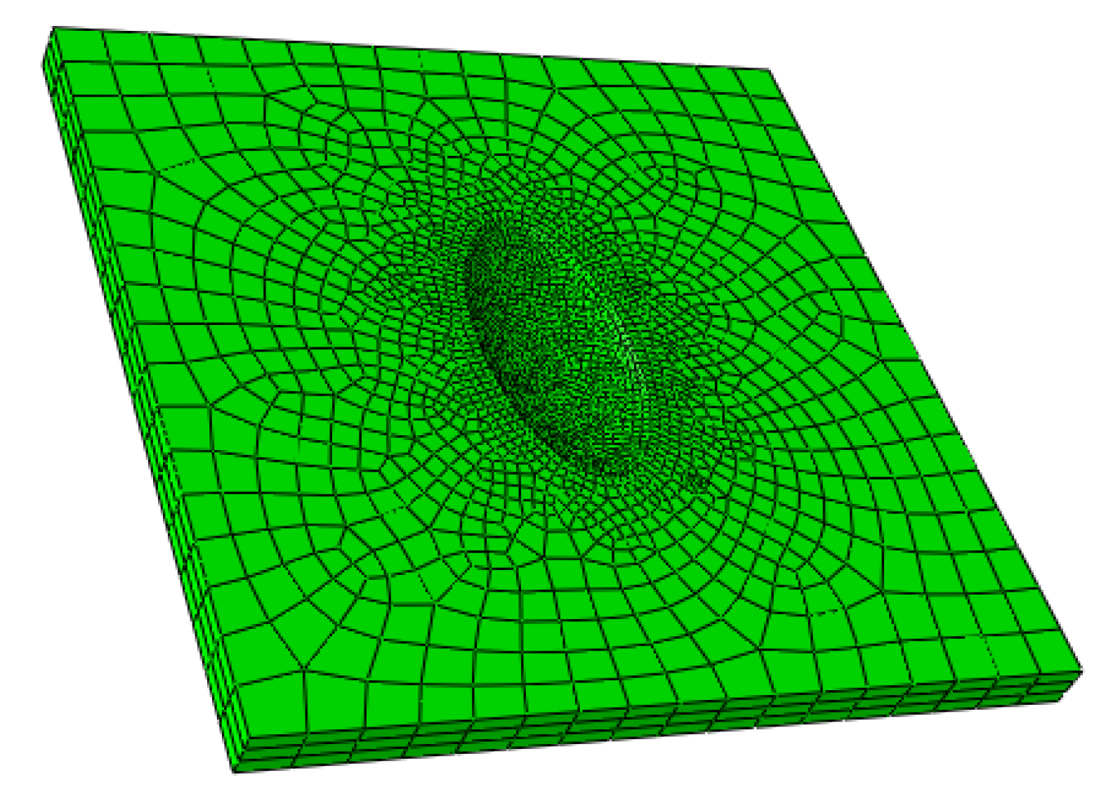
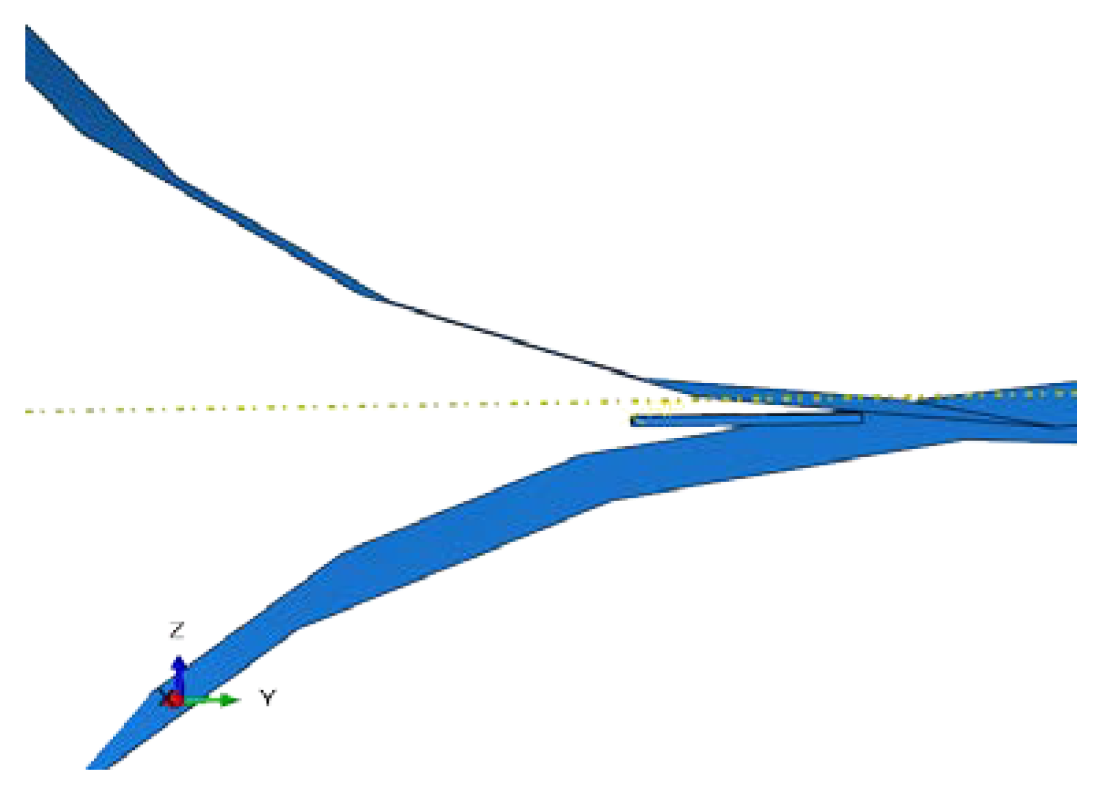
When establishing a finite-element model, it is important to select the type of cell: the form of the divided grid will have a direct impact on the calculation accuracy and scale [26]. The cells were divided by a hexahedral mesh (C3D8R). The key to solving the crack problem was to calculate the stress field at the end of the crack. To maintain calculation accuracy, a modified computational grid was designed as a cracked singular element and was only locally encrypted in the surrounding area. Mesh generation of a cold-rolled sheet was shown in Figure 2. A three-layer grid was set for all thickness directions, and the mesh discretization met geometric, physical, and technical requirements. After the division was completed, the number of cells in each model was approximately 4000 and the number of nodes was approximately 5000. The stress and strain changes of the rolled piece during the rolling process were studied, so the rolled piece was set as an elastoplastic body and the roll was set as a discrete rigid body. The geometric model considered only two work rolls, was shown in Figure 3.

2.3. Boundary and Initial Conditions

The rolling stock and work roll had two contact modes during the cold-rolling numerical simulation process: the first was that the grinding portion was in contact with the work roll body; the second was contact of the remaining portion with the work roll body. During rolling, the rolling piece gradually moved forward to reach the roll gap so that the rolling process could be started by frictional biting of the piece by the work roll body. The friction coefficient was constant during the rolling process and the contact type was surface contact. The friction coefficient between the two materials was set to 0.12.
Eleven analysis steps were set in the rolling process, five of which were used to control the distance between the roll gaps and the direction in which the rolling stock moved to achieve reversible rolling. The initial speed of the rolled piece was set to 500 mm/s. Before entering the roll, the set speed was cancelled and the rolling stock was allowed to rely on inertia to enter the next pass. During the rolling process, the rolling stock moved in the y-direction by the initial speed and had no displacement constraint in other directions; the rolls had no displacement in all directions and only rotated about the center line. The edge of a roll was restrained so that its displacement in all directions was zero and rotation could only occur about the x-axis. The rotation speed of the rolls was 7.85 rad/s.

3. Results

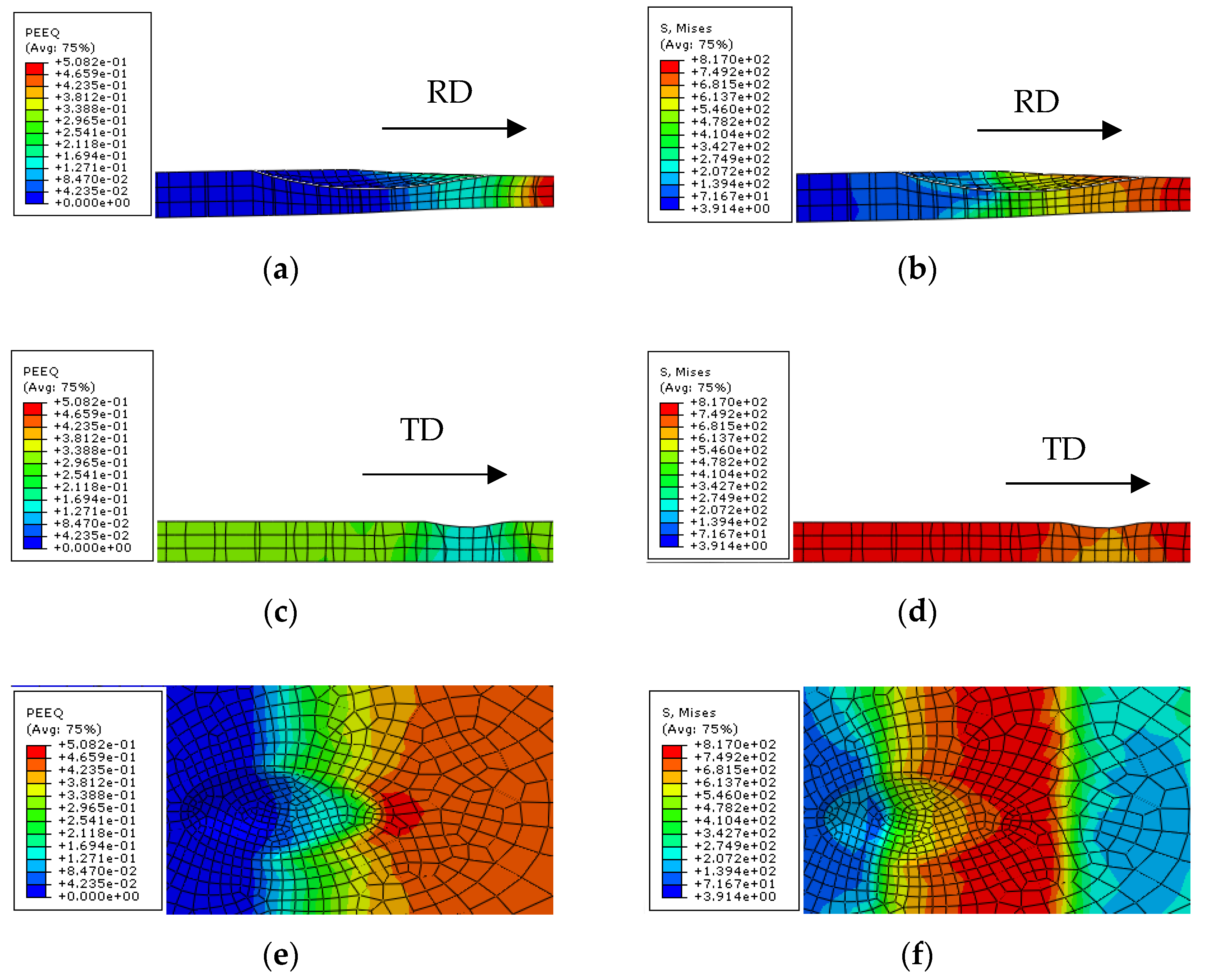
Stress-strain cloud diagrams generated during the first-pass rolling of the 3 mm titanium strip surface with a 0.25 mm grinding depth pit are shown in Figure 4, where PEEQ is the equivalent strain and S is the Mises stress. The grinding pits were eliminated after the first-pass rolling.
The stress and strain cloud diagrams show that the stress increased rapidly as the sheet entered the roll. As the rolling piece gradually entered the roll, the rate of the stress increase gradually decreased; the upper surface received greater stress than the lower surface. As grinding approached the central area of the pit, the stress became larger. On completion of rolling, the residual stress and equivalent effect variable in the edge region of the grinding were significantly higher than in other positions. Stress and strain data processing were performed at the center point of the pit and observed with time.
The rolling reduction of the first pass was 1 mm, so strips with ground depths of 1.5 mm and 2 mm (greater than the first-pass reduction) were analyzed. The stress-strain cloud diagrams are shown in Figure 5. The grinding pits were not eliminated after the first-pass rolling. Compared with the first pass, the second pass had larger equivalent strains on the normal direction (ND) and transverse direction (TD) faces; the equivalent strains at the front and back ends of the RD plane were the opposite. Residual stress in the front end of ND was larger than that in the back end and there was strong residual stress in the middle of the RD.
The stress and strain changes in the center of the multi-pass rolling process are shown in Figure 6 for a grinding pit of 0.25 mm depth. The center point of the pit was first subjected to tensile stress in the x-direction (TD) and then the tensile stress gradually changed to compressive stress when entering the rolling zone; in the y-direction (RD), compressive stress was applied and, as the rolling process progressed, compressive stress was converted into tensile stress. The tensile stress at the grinding center exceeded the tensile strength, but its strain was only 0.38, which did not exceed the ultimate strain. The two fracture conditions required for a metallic material are to reach the limit of its fracture strength and to exceed its ultimate strain. In the z-direction (ND), tensile stress was first applied; as the rolling process progressed, the tensile stress gradually decreased and transformed into compressive stress.
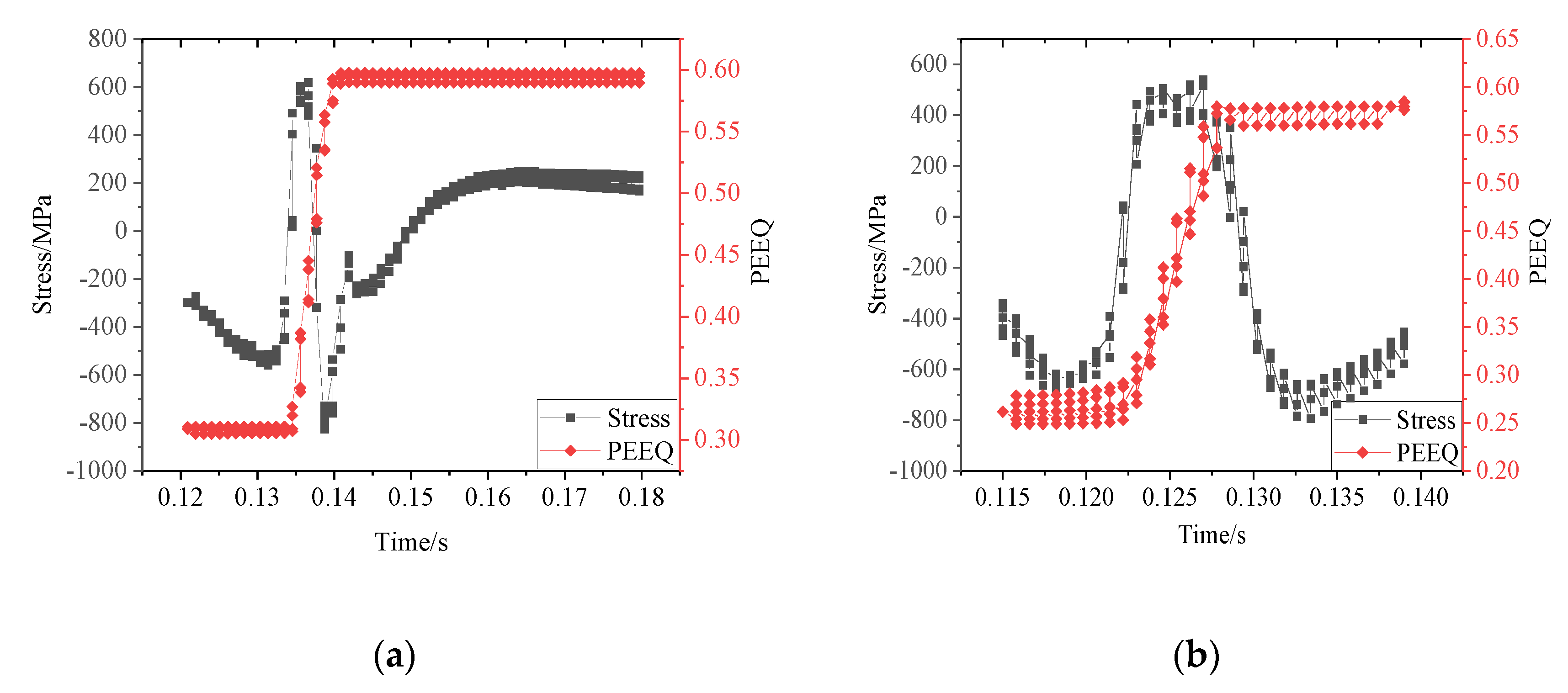
Figure 7 and Figure 8 show the relationships between the tensile stress and strain of the CP-Ti strip for grinding pit depths of 0.25 mm, 0.5 mm, and 0.75 mm, respectively, during the first-pass rolling interval. The RD stress at the bottom of the 0.25 mm pit did not reach the tensile strength (312 MPa) of the material, so it did not break after the first pass (fracture condition 1: reaching the breaking strength limit; 2: reaching the elongation limit). Although the partial stresses at the bottoms of the 0.5 mm and 0.75 mm pits exceeded the tensile strength of the material, the strains did not reach the strain limit, so the bottoms of the pits did not fracture after the first rolling. Analysis of changes in stress and strain during the second pass with time showed that when the center point produced strain, the RD stress became negative, that is, it was subject to compressive stress. Combined with data from the stress-strain cloud diagrams, it was concluded that the surface grinding trace disappeared after the first pass of rolling, so the center point would not be affected by compressive stress in the RD; in other words, the material would not form cracks in the subsequent rolling process.
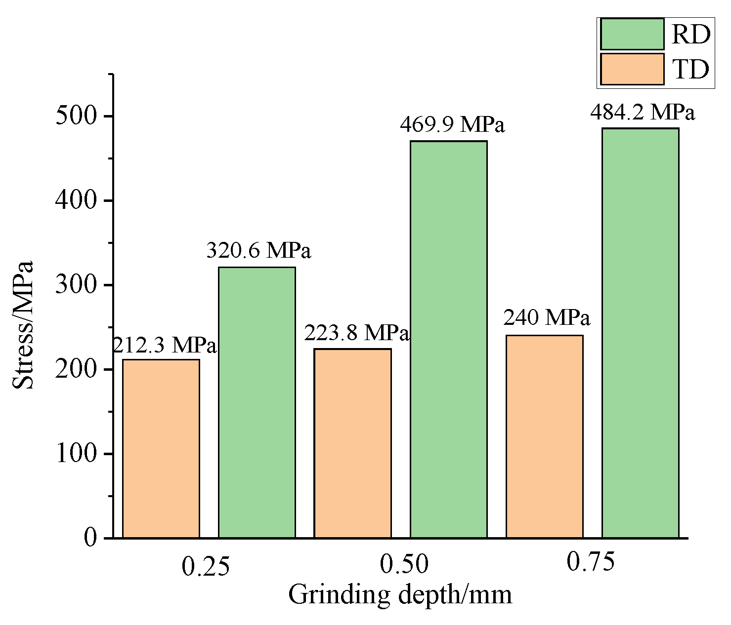
Figure 9 shows that the transverse tensile stress of the CP-Ti strip during the cold-rolling process was small and the tensile stress in the RD was larger. It was therefore necessary to analyze the relationship between the stress and strain of the materials with time in the RD. When the stress and strain exceeded the critical point of fracture during the cold-rolling process, the CP-Ti strip would crack.
After two passes of rolling, the surface of the strip with a 1.5 mm grinding depth had become flat, while that with a 2 mm depth still had a little pit. In the second-pass stress-strain cloud diagram for 2 mm grinding depth, the stress and strain at the center point were higher than at the edge portion, which is why the strip was easily broken at the center after grinding. As mentioned above, the grinding center point had the greatest influence on the tensile stress during the rolling process and the strain at the center point could not reach the ultimate strain during the first pass. We therefore directly analyzed the relationship between RD stress and strain with time for the second passes of strips with 1.5 mm and 2 mm grinding depths, as shown in Figure 10.
It is necessary to pass the tensile test to obtain the ultimate fracture strain ( ε C r ). It could be determined whether cracking occurred by reviewing the results of numerical simulation, comparing the tensile stress of the material with its fracture strength, and comparing the relationship between ε C r and the calculated maximum tensile strain. A cracking criterion was thus proposed.
Using the stress-strain curves of the second-pass rolling, we determined that when the strain of the 1.5 mm grinding depth center point reached ultimate strain, partial stress in the RD had become compressive stress, so the material would not break. After the second pass, the surface of the material had been flattened and subsequent passes would only be subjected to compressive stress, so the final material would not crack. When the stress of the 2 mm grinding depth center point was 520 MPa (the tensile strength was 302 MPa), the strain reached 0.6, which exceeded the ultimate strain, so the material cracked after being subjected to tensile stress in the RD. Combined with the numerical simulation results, the conditions for preventing cracking of a grinding are given by:
ln ( 1 + h H ) ε C r ,
where H is strip thickness (mm) and h is grinding depth (mm).
Parameters of the 1.5 mm grinding depth cold-rolling simulation were substituted into Equation (1) to obtain ln ( 1 + h H ) = 0.4 : the ultimate fracture strain was 0.49 (the real strain was 0.40), so the material would not crack; substituting 2 mm into ln ( 1 + h H ) = 0.51 showed that the material would crack.

4. Cold-Rolling Test Verification

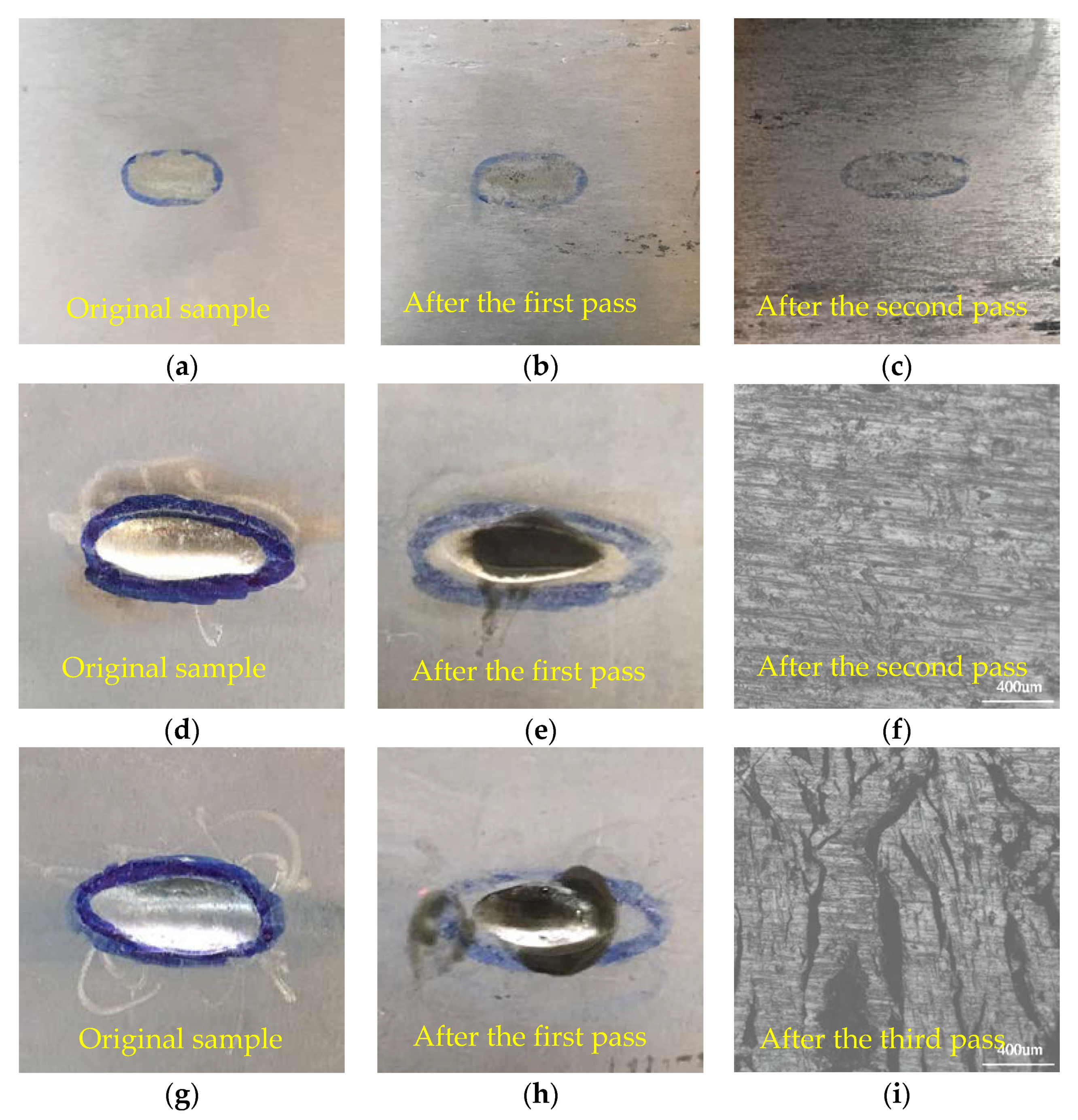
Three 100 mm × 40 mm pieces of hot-rolled CP-Ti sheets were cut and then ground in the center. The shape of the grind was oval, with long and short axes of 20 mm and 10 mm, respectively. The grinding depths were 0.25 mm, 1.5 mm, and 2 mm. Cold-rolling tests were carried out using a four-roll cold-rolling mill. The thickness of raw material for cold rolling was 3 mm, and the thickness of titanium strip after each pass was 2.5 mm, 1.5 mm, 1.0 mm, 0.8 mm, 0.6 mm, and 0.4 mm respectively. A maximum of 6 passes are rolled. After each pass of rolling, use a microscope to observe whether there is a crack in the center of the grinding position. If there are cracks, stop the subsequent pass rolling.
As shown from the test results in Figure 11, the grinding trace of CP-Ti sheets with a grinding depth of 0.25 mm disappeared after the first pass and no cracks were produced thereafter. After the second pass with 1.5 mm grinding depth, the grinding trace disappeared and there was no cracking. After the third pass, the grinding trace of a depth of 2 mm disappeared and the grinding center cracked. These data were consistent with the numerical simulation results.
Because of the work hardening in the cold working process, the deformation from the previous pass can accumulate to the next pass, causing the grinding position to crack due to the accumulated strain and tensile stress. Work hardening and tensile stress during cold rolling cause fracture, but it can be eliminated by recrystallization annealing. Based on calculations and test results, it is recommended that the titanium strips should be annealed and subsequently rolled before the cavities nucleation merges to cause fracture, which can avoid cracking in the grinding zone and breakage during the rolling process. Alternatively, limit the grinding depth according to the thickness of titanium strip. After the intermediate recrystallization annealing, further grinding is carried out to eliminate the defects, so as to prevent the cracking of the grinding center in the subsequent rolling.

5. Conclusions

(1) During rolling, the stress and strain at the grinding center were larger than those at its edge, so the center was easily cracked during the rolling process.
(2) By decomposition of the stress in the grinding center of the rolling zone, it was found that the effect of RD stress was greater than that of transverse stress, so the material was likely to exhibit transverse fracture. When the material was in strain, the RD of the grinding center was first affected by the tensile stress, then the tensile stress decreased and gradually changed into compressive stress.
(3) In the cold-rolling simulation of strips with different grinding depths, only the strip with 2 mm grinding depth simultaneously exceeded the limiting values of tensile stress and true strain in the second-pass RD, that is,   ln ( 1 + h H ) ε C r , so the material cracked. Grinding was repaired in strips with smaller grinding depths.

Author Contributions

Conceptualization, W.Y. and E.D.; methodology, J.Z.; model, Z.Z.; validation, J.Z., J.S. and G.G.; formal analysis, J.Z.; investigation, J.Z.; resources, Z.Z.; data curation, Z.Z.; writing—original draft preparation, J.Z.; writing—review and editing, J.Z.; visualization, J.Z.; supervision, W.Y.; project administration, W.Y.; funding acquisition, W.Y. All authors have read and agreed to the published version of the manuscript.

Funding

This research was funded by "13th Five Years Plan" National Key R&D Project (No. 2016YFB030 1200).

Acknowledgments

We thank Kathryn Sole, from Liwen Bianji, Edanz Group China (www.liwenbianji.cn/ac), for editing the English text of a draft of this manuscript.

Conflicts of Interest

The authors declare no conflict of interest.

References

  1. Hubert, C.; Dubar, L.; Dubar, M.; Dubois, A. Finite Element simulation of the edge-trimming/cold rolling sequence: Analysis of edge cracking. J. Mater. Process. Technol. 2012, 212, 1049–1060. [Google Scholar] [CrossRef]
  2. Lin, D.; Wang, L.; Meng, F.Q.; Cui, J.Z.; Le, Q.C. Effects of second phases on fracture behavior of Mg-10Gd-3Y-0.6Zr alloy. Trans. Nonferrous Met. Soc. China 2010, 20, 421–425. [Google Scholar] [CrossRef]
  3. Kwon, H.C.; Lee, H.W.; Kim, H.Y.; Lm, Y.T.; Park, H.D.; Lee, D.L. Surface wrinkle defect of carbon steel in the hot bar rolling process. J. Mater. Process. Technol. 2009, 209, 4476–4483. [Google Scholar] [CrossRef]
  4. Zhao, J.W.; Huo, M.S.; Ma, X.G.; Jia, F.H.; Jiang, Z.Y. Study on edge cracking of copper foils in micro rolling. Mater. Sci. Eng. A 2019, 747, 53–62. [Google Scholar] [CrossRef]
  5. Zhou, Y.; Mo, J.L.; Cai, Z.B.; Deng, C.G.; Peng, J.F.; Zhu, M.H. Third-body and crack behavior in white etching layer induced by sliding–rolling friction. Tribol. Int. 2019, 140, 105882. [Google Scholar] [CrossRef]
  6. Chen, G.; Ren, C.Z.; Lu, L.P.; Ke, Z.H.; Qin, X.D.; Ge, X. Determination of ductile damage behaviors of high strain rate compression deformation for Ti-6Al-4V alloy using experimental numerical combined approach. Eng. Fract. Mech. 2018, 222, 499–520. [Google Scholar] [CrossRef]
  7. Wang, L.N.; Shi, Y.D.; Zhang, Y.L.; Bai, Y.; Lei, S. Ductile-to-brittle fracture of CP titanium with torsion deformation. Mater. Lett. 2018, 217, 263–266. [Google Scholar] [CrossRef]
  8. Yang, C.P.; Dong, H.B.; Hua, Z.H. Micro-mechanism of central damage formation during cross wedge rolling. J. Mater. Process. Technol. 2018, 252, 322–332. [Google Scholar] [CrossRef]
  9. Katani, S.; Madadi, F.; Atapour, M.; Rad, S.Z. Micromechanical modelling of damage behavior of Ti–6Al–4V. Mater. Des. 2013, 49, 1016–1021. [Google Scholar] [CrossRef]
  10. Tvergaard, V.; Needleman, A. Analysis of the cup-cone fracture in a round tensile bar. Acta Metall. 1984, 32, 157–169. [Google Scholar] [CrossRef]
  11. Li, J.; Su, C.Y.; Lu, L.; Zhang, p.; Chang, L.; Miao, X.T.; Zhou, B.B.; He, X.H.; Zhou, C.Y. Investigation on fatigue crack growth behavior for commercial pure titanium at different crack tip plastic deformed levels. Theor. Appl. Fract. Mech. 2019, 100, 1–13. [Google Scholar] [CrossRef]
  12. Zhu, Y.C.; Zeng, W.D.; Zhao, Y.Q. Influence of Deformation Parameters on Fracture Mechanism of Ti40 Titanium Alloy. Rare Metal Mater. Eng. 2017, 46, 1207–1213. [Google Scholar]
  13. Briffod, F.; Bleuset, A.; Shiraiwa, T.; Enoki, M. Effect of crystallographic orientation and geometrical compatibility on fatigue crack initiation and propagation in rolled Ti-6Al-4V alloy. Acta Mater. 2019, 177, 56–67. [Google Scholar] [CrossRef]
  14. Ahmed, S.; Ahsan, Q.; Kurny, A.S.W. Effect of rolling on tensile and fracture of Al-4.5Cu-3.4Fe cast composite. J. Mater. Technol. 2007, 182, 215–219. [Google Scholar] [CrossRef]
  15. Zhao, M.Y.; Zhou, Z.J.; Zhong, M.; Tan, J. Effect of hot rolling on the microstructure and fracture behavior of a bulk fine-grained W–Y2O3 alloy. Mater. Sci. Eng. A 2015, 646, 19–24. [Google Scholar] [CrossRef]
  16. Turczyn, S. The effect of the roll-gap shape factor on internal defects in rolling. J. Mater. Process. Technol. 1996, 60, 275–282. [Google Scholar] [CrossRef]
  17. Nioi, M.; Pinna, C.; Celotto, S.; Swart, E.; Farrugia, D.; Husain, Z.; Ghadbeigi, H. Finite element modelling of surface defect evolution during hot rolling of Silicon steel. J. Mater. Process. Technol. 2019, 268, 181–191. [Google Scholar] [CrossRef]
  18. Lemaitre, J. A continuous damage mechanics model for ductile fracture. J. Eng. Mater. Technol. Trans. ASME 1985, 107, 83–89. [Google Scholar] [CrossRef]
  19. Soyarslan, C.; Tekkaya, A.E. Prevention of internal cracks in forward extrusion by means of counter pressure: A numerical treatise. Steel Res. Int. 2009, 80, 671–679. [Google Scholar]
  20. Mashayekhi, M.; Torabian, N.; Poursina, M. Continuum damage mechanics analysis of strip tearing in a tandem cold rolling process. Simul. Model. Pract. Theory 2011, 19, 612–625. [Google Scholar] [CrossRef]
  21. Yan, Y.X.; Sun, Q.; Chen, J.J.; Pan, H.L. The initiation and propagation of edge cracks of silicon steel during tandem cold rolling process based on the Gurson–Tvergaard–Needleman damage model. J. Mater. Process. Technol. 2013, 213, 598–605. [Google Scholar] [CrossRef]
  22. Sun, Q.; Chen, J.J.; Li, X.X.; Pan, H.L. Parametric Study of Edge Crack of Silicon Steel Strip in Cold Rolling based on a Shear Modified GTN Damage Model. Procedia Mater. Sci. 2014, 3, 1632–1637. [Google Scholar] [CrossRef] [Green Version]
  23. Sun, Q.; Zan, D.Q.; Chen, J.J.; Pan, H.L. Analysis of edge crack behavior of steel sheet in multi-pass cold rolling based on a shear modified GTN damage model. Theor. Appl. Fract. Mech. 2015, 80, 259–266. [Google Scholar] [CrossRef]
  24. Dwivedi, S.; Rana, R.S.; Rana, A.; Rajpurohit, S.; Purohit, R. Investigation of damage in small deformation in hot rolling process using FEM. Mater. Today Proc. 2017, 4, 2360–2372. [Google Scholar] [CrossRef]
  25. Zhang, D.F.; Dai, Q.W.; Fang, L.; Xu, X.X. Prediction of edge cracks and plastic-damage analysis of Mg alloy sheet in rolling. Trans. Nonferrous Met. Soc. China 2011, 21, 1112–1117. [Google Scholar] [CrossRef]
  26. Xing, J.Z.; Li, J. ANSYS modeling method and mesh generation. China Water Transp. 2006, 9, 116–118. [Google Scholar]
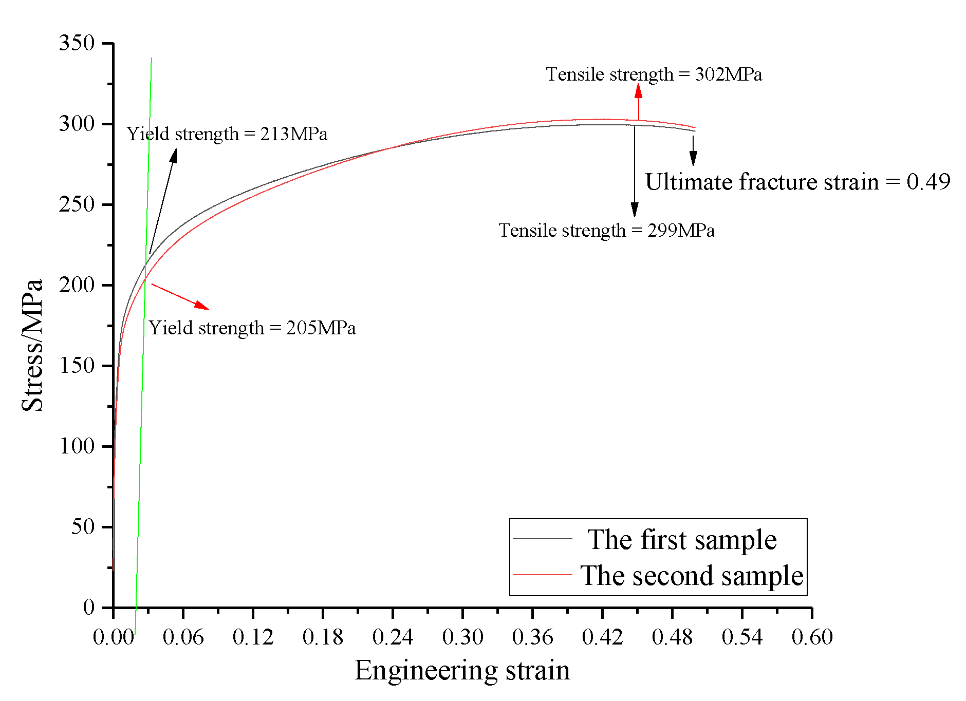
Figure 1. Stress-strain curve of test material.
Metals 10 00323 g001
Figure 2. Mesh generation of a cold-rolled sheet.
Metals 10 00323 g002
Figure 3. Rolling model.
Metals 10 00323 g003
Figure 4. Stress-strain cloud diagrams of the rolling deformation zone for a strip with 0.25 mm grinding depth. Rolling direction (RD) (a) strain and (b) stress in cross section; transverse direction (TD) (c) strain and (d) stress in cross section; (e) stress and (f) strain cloud diagrams of the ground pit in the deformation zone.
Metals 10 00323 g004
Figure 5. Stress-strain cloud diagrams of the deformation zone in first-pass rolling of strip with 1.5 mm grinding depth. Rolling direction (RD) (a) strain and (b) stress in cross section; transverse direction (TD) (c) strain and (d) stress in cross section; (e) stress and (f) strain cloud diagrams of ground pit in the deformation zone.
Metals 10 00323 g005
Figure 6. Partial stress at the center of a 0.25 mm pit. Center-point (a) stress of first-pass rolling and (b) strain of each rolling pass.
Metals 10 00323 g006
Figure 7. (a) Changes in stress and strain with time for a strip with a 0.25 mm grinding depth (first pass); (b) changes of stress and strain with time for a strip with a 0.5 mm grinding depth (first pass).
Metals 10 00323 g007
Figure 8. Changes in stress and strain with time for a strip with a 0.75 mm grinding depth, showing deformation of (a) first and (b) second passes.
Metals 10 00323 g008
Figure 9. Maximum values of TD and RD stresses of pit center during the first pass deformation zone.
Metals 10 00323 g009
Figure 10. Changes in RD partial stress and strain with time in the second pass of strips with (a) 1.5 mm grinding depth and (b) 2.0 mm grinding depth.
Metals 10 00323 g010
Figure 11. Contrasts in results of cold-rolling tests for strips with grinding depths of (ac) 0.25 mm, (df) 1.5 mm, and (gi) 2 mm.
Metals 10 00323 g011
Table 1. Parameters of cold-rolling simulation.
CP-Ti StripRoll
Density (kg·m−3)Elastic Modulus (MPa)Poisson ratioSize (m)Length (m)Diameter (m)
4510108,5440.30.05 × 0.05 × 0.0031.250.5
Table 2. Deformation resistance parameters of cold-rolling cracking.
ε ˙ = 10 4 s 1 ε ˙ = 10 2 s 1 ε ˙ = 10 0 s 1 ε ˙ = 10 1 s 1
σεσεσεσε
3230324040004300
4300.074520.075240.075860.07
5010.165240.166050.166870.16
5640.265960.257020.267440.26
6120.356220.357260.368020.35
6700.456840.457610.458160.45