Multi-Objective Optimization of Intermediate Roll Profile for a 6-High Cold Rolling Mill


Abstract
:1. Introduction
2. Coupling Model of Roll Profile and Strip Flatness
2.1. Calculation of Roll Gap Profile of SmartCrown Intermediate Roll
2.2. Calculation of Contact Pressure Distribution between Rolls
2.3. Calculation of Cold Rolled Strip Flatness
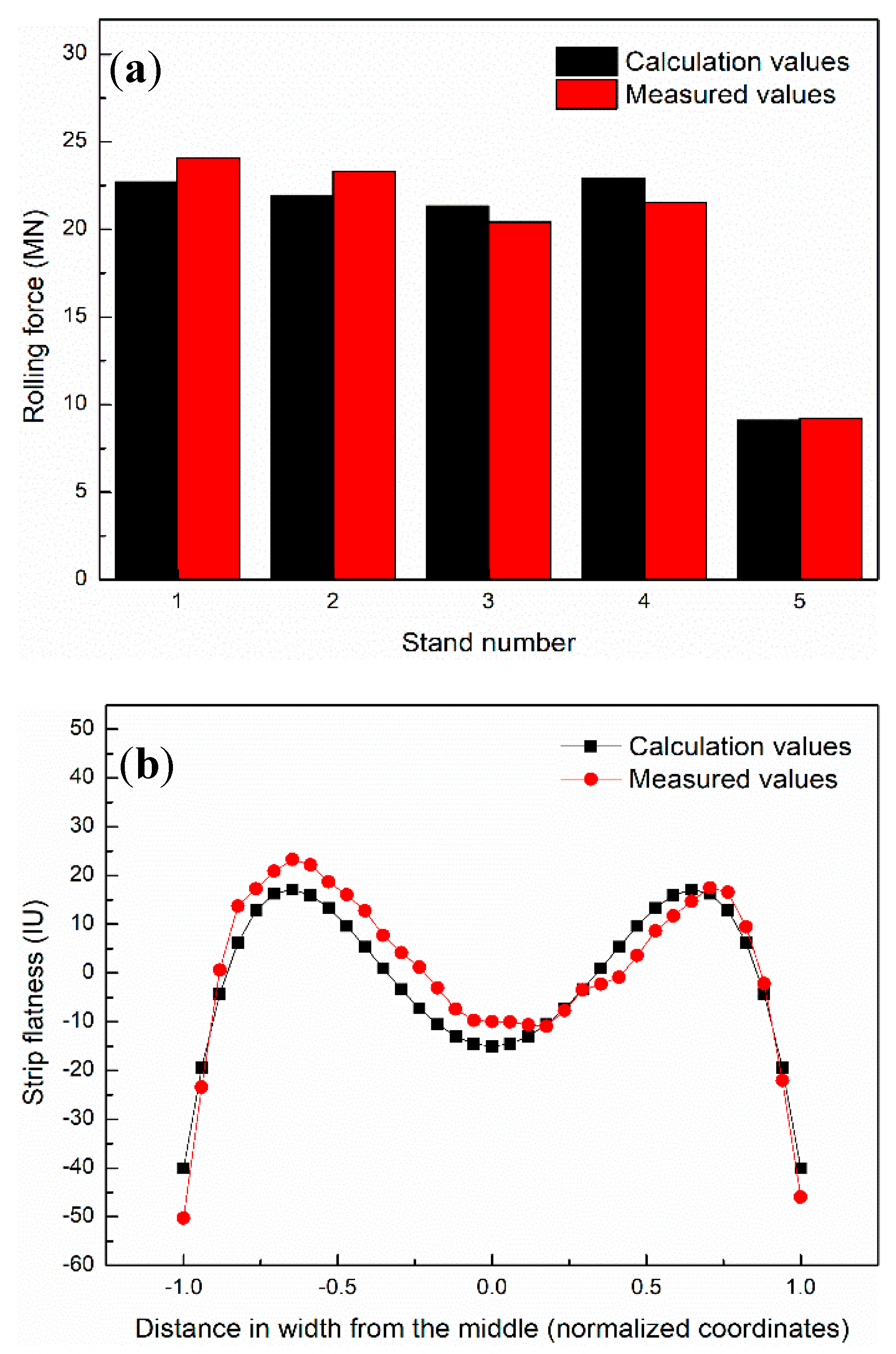
2.4. Verification of the Coupling Model
3. Flatness Control Characteristics of SmartCrown Intermediate Roll
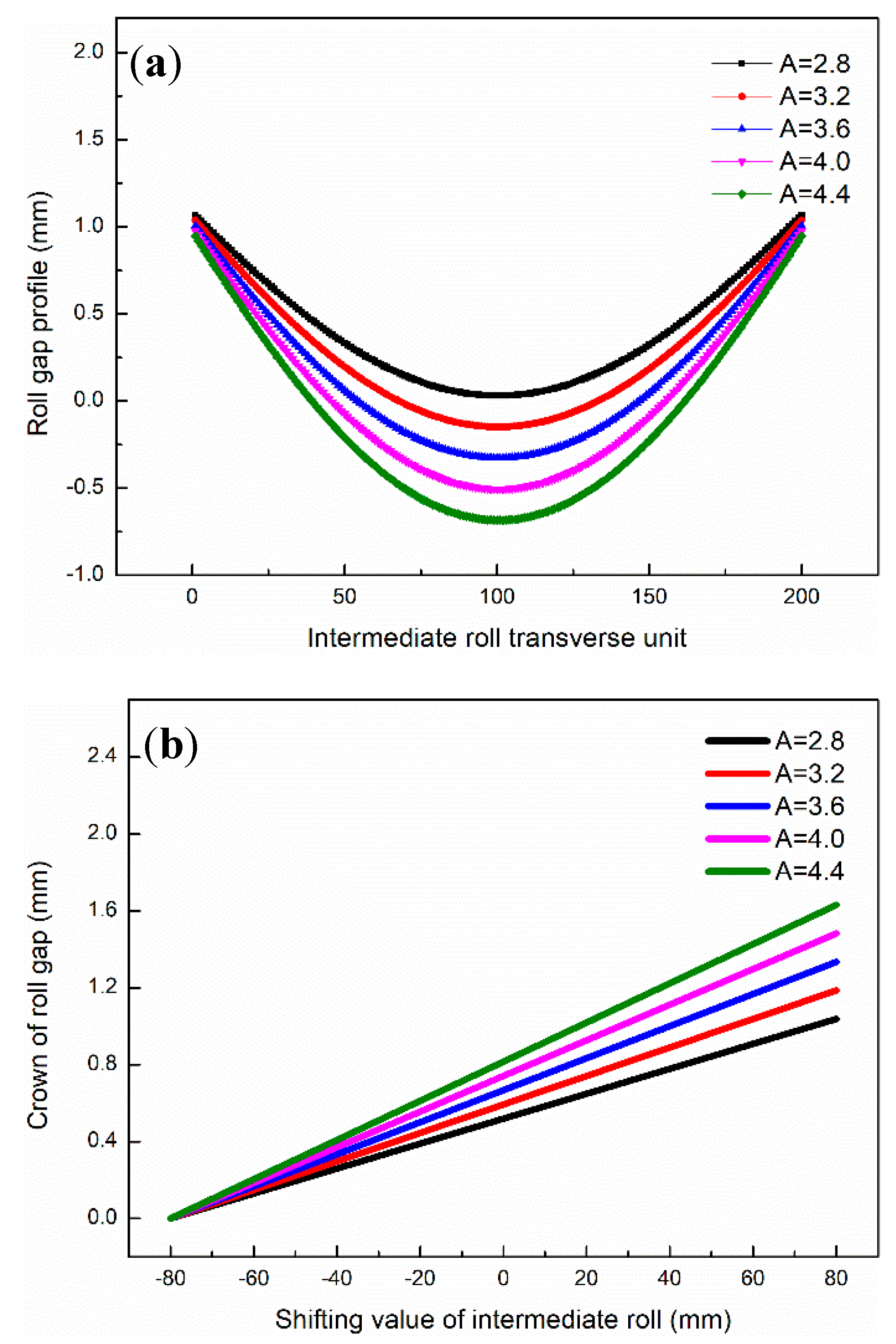
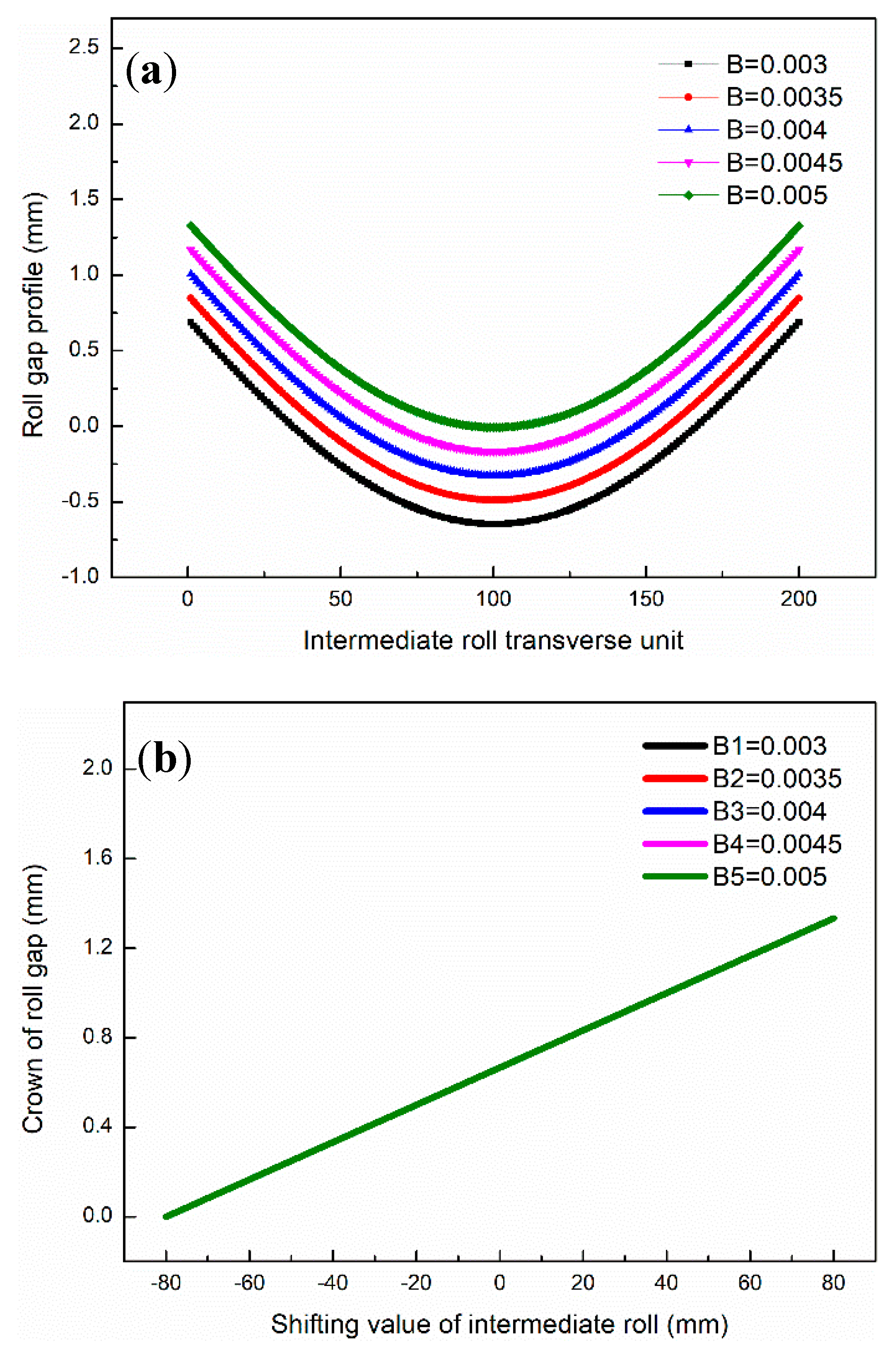
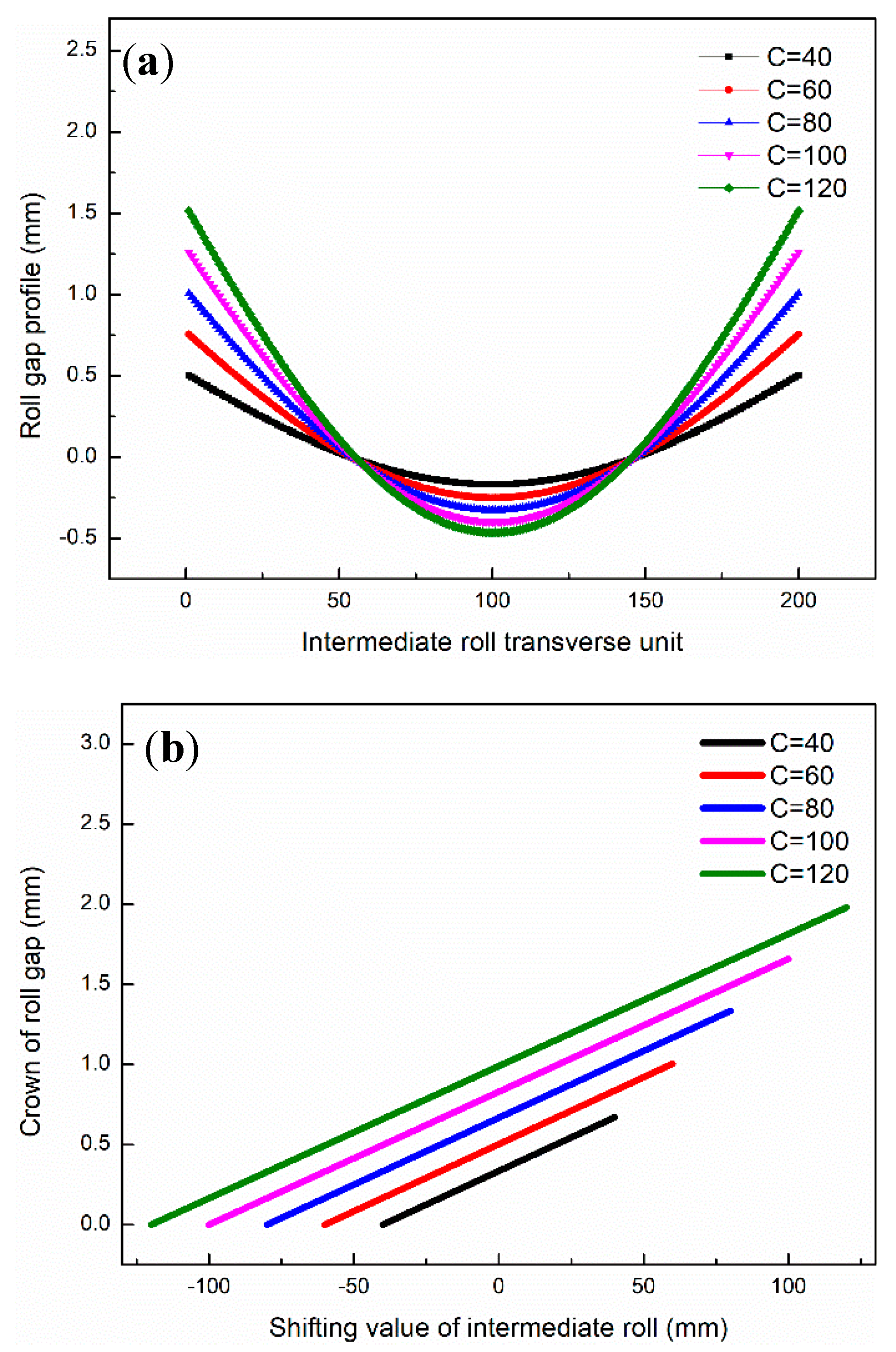
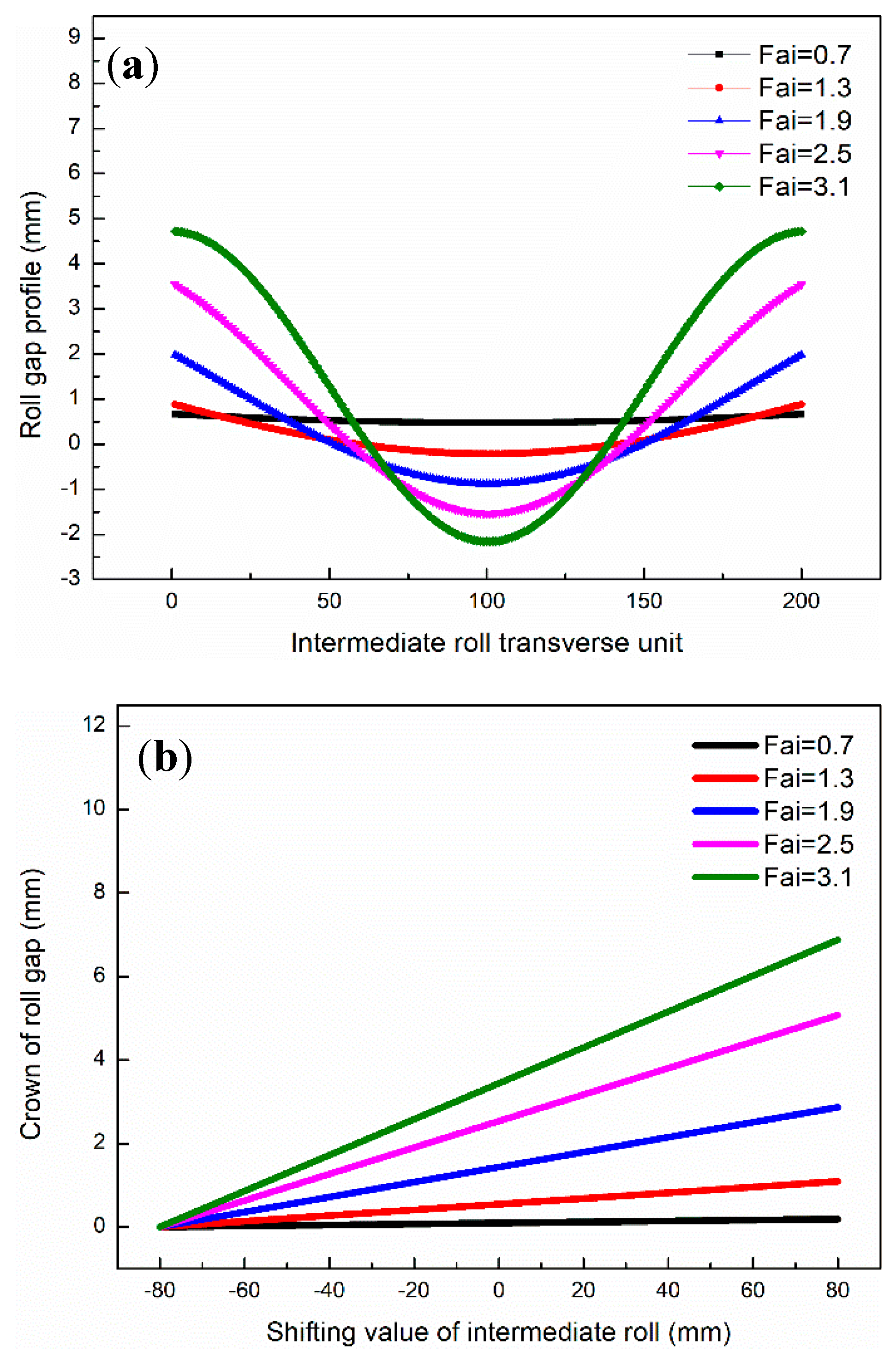
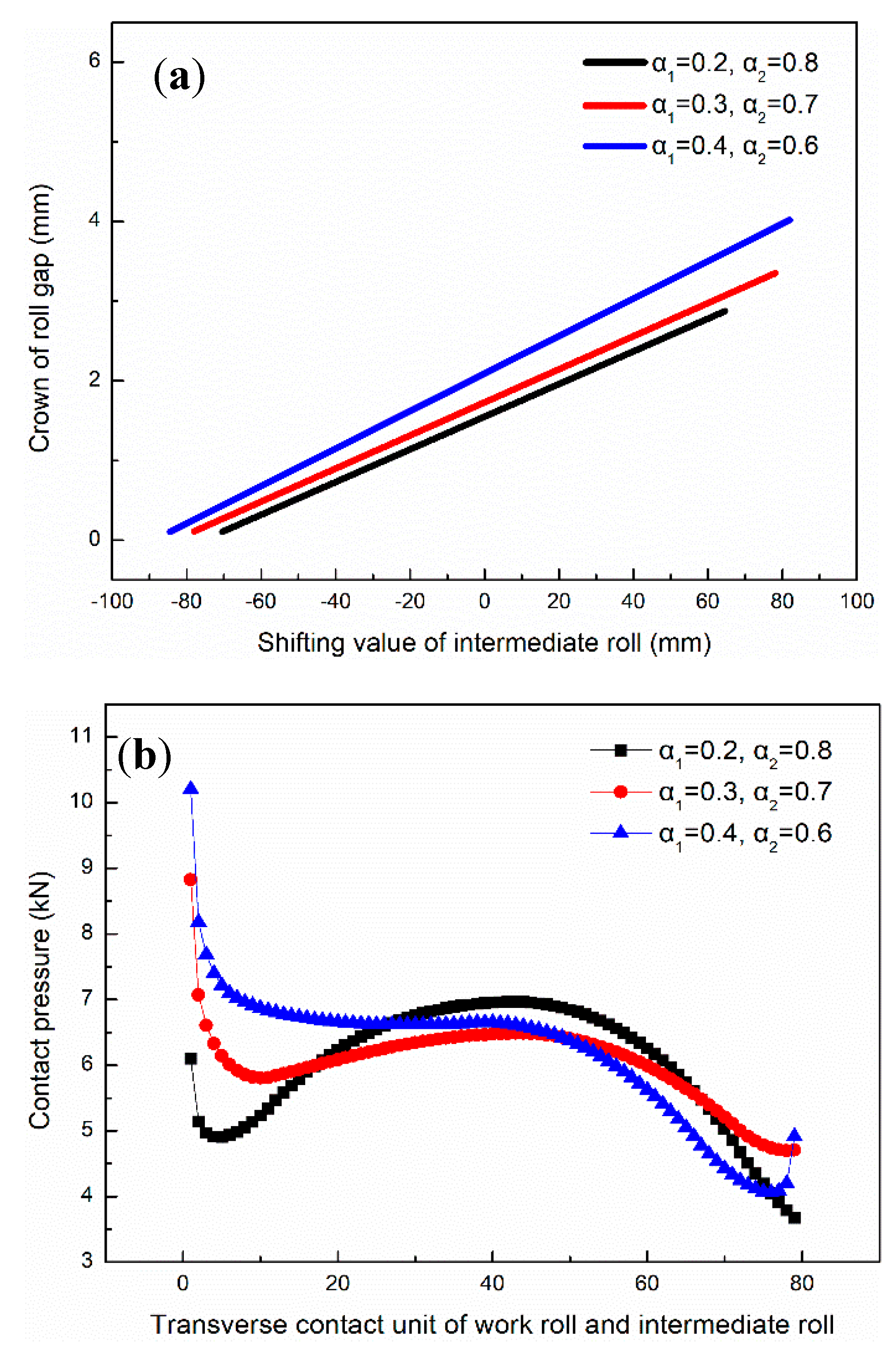
3.1. Effect of Profile Parameters on Roll Gap
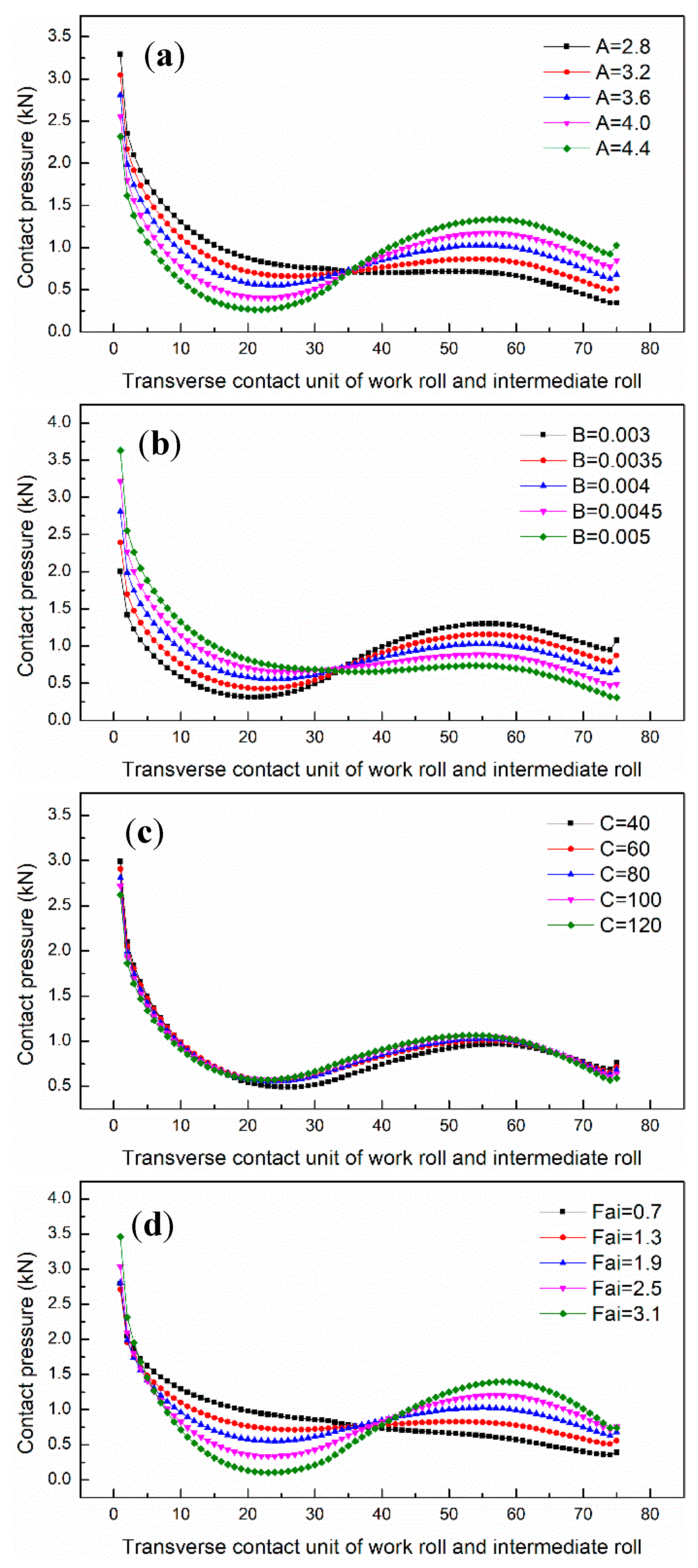
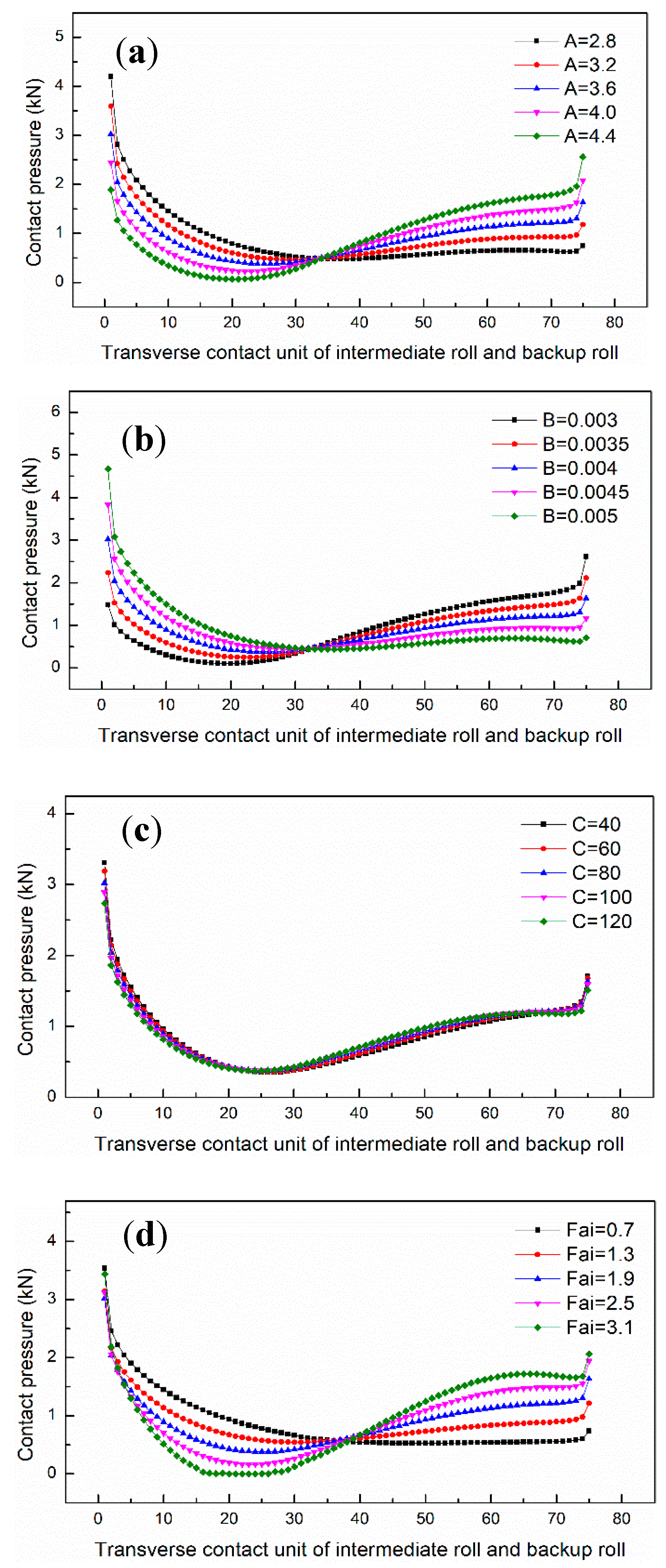
3.2. Effect of Profile Parameters on Contact Pressure Between Rolls
3.3. Effect of Profile Parameters on Strip Flatness
4. Multi-Objective Optimization of SmartCrown Intermediate Roll
4.1. Multi-Objective Functions
4.2. Constraint Conditions
4.3. Roll Profile Parameters Optimization Procedure
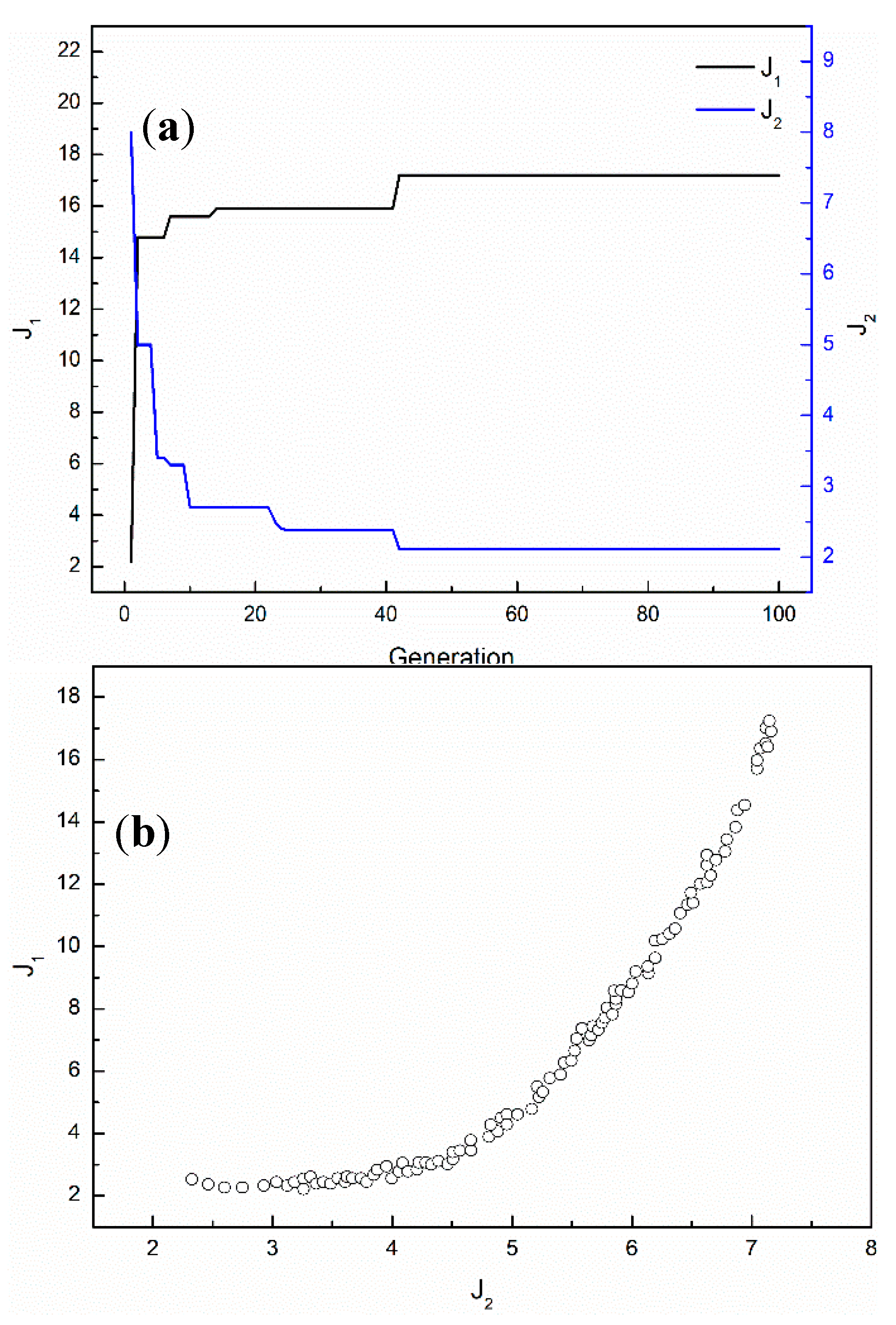
4.4. Multi-Objective Optimization Results
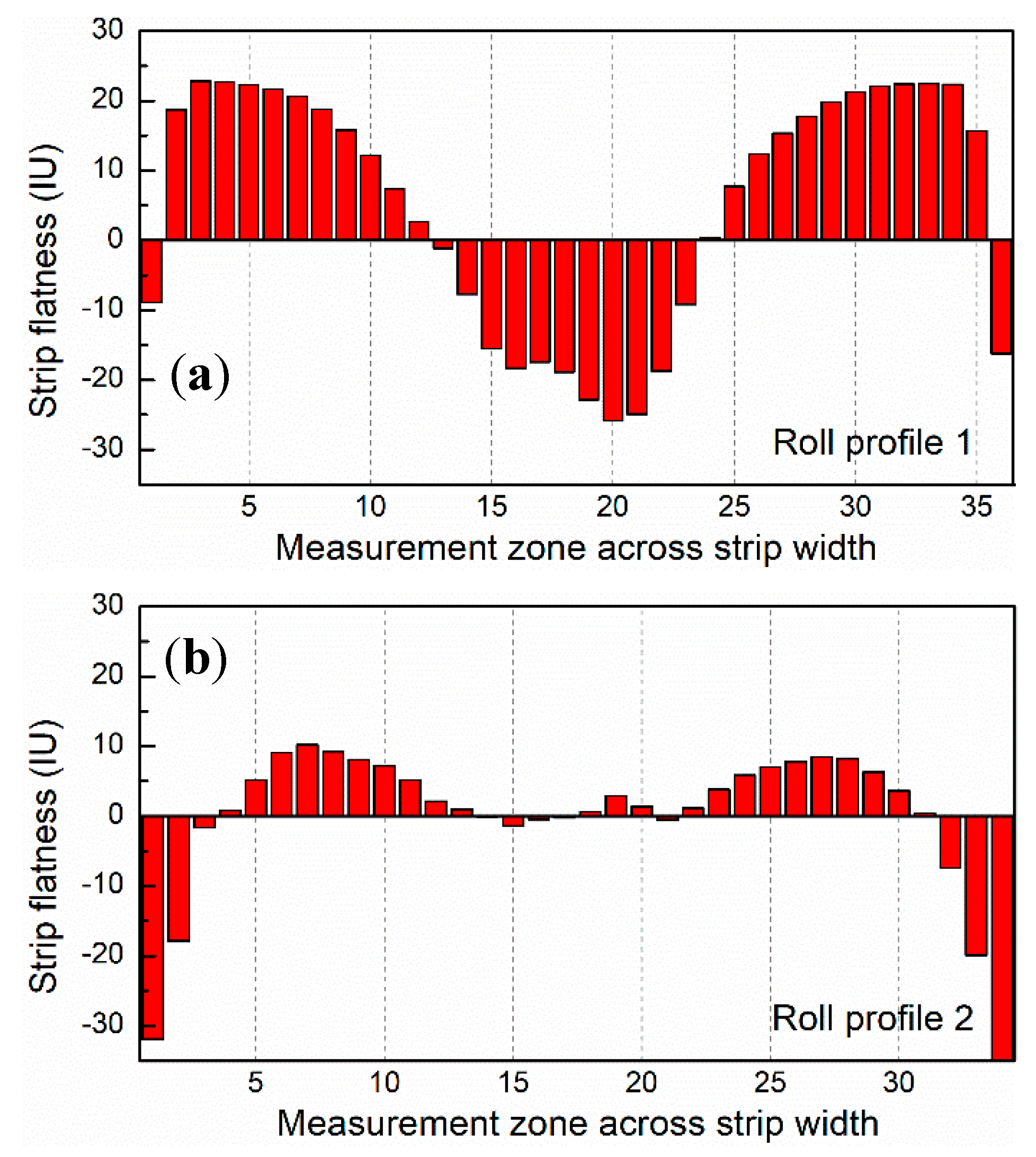
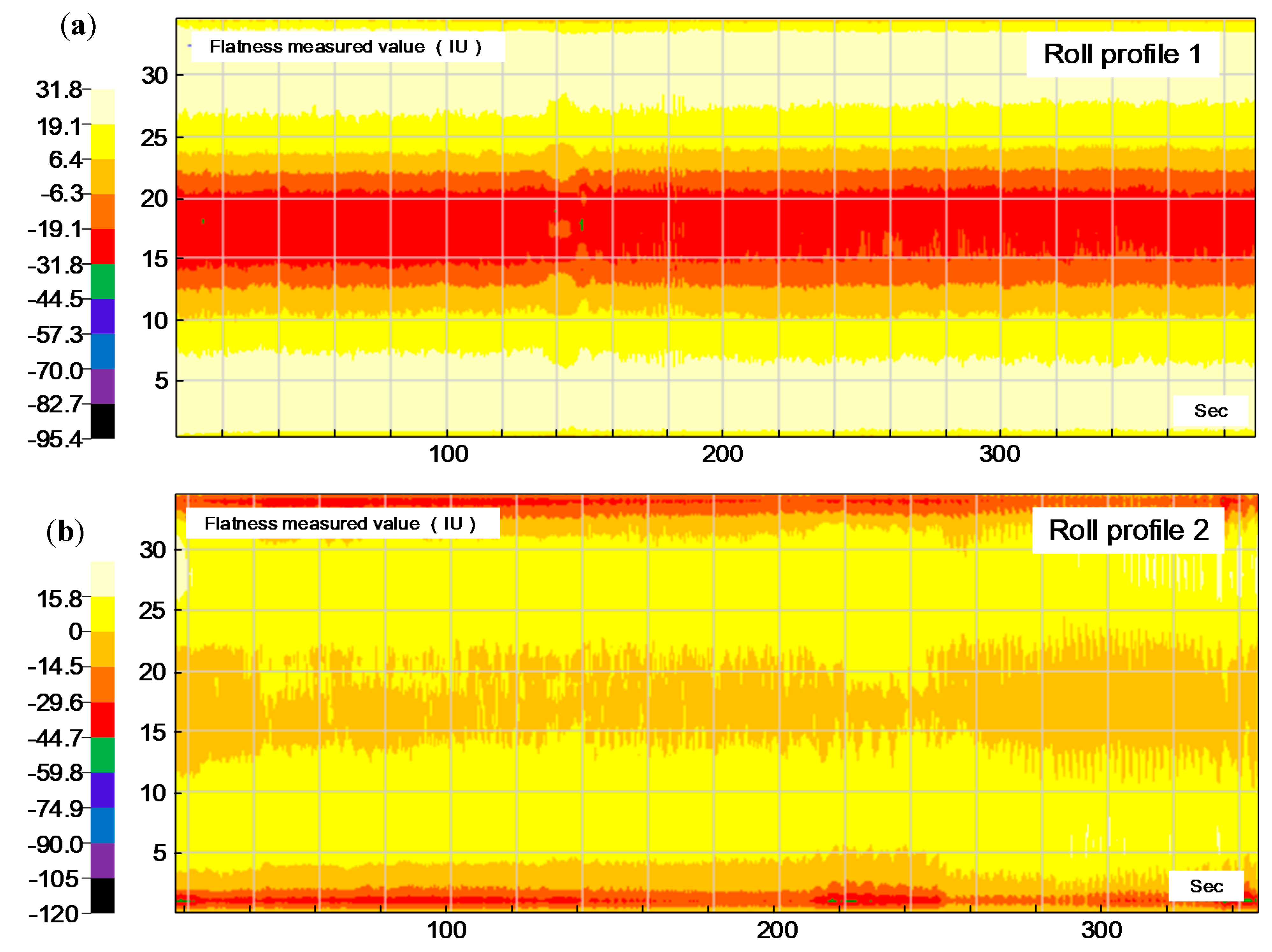
5. Industrial Test and Application
6. Conclusions
- A Coupling model of roll profile and strip flatness was established and verified. The relative error of the rolling force that was calculated by the model was less than 6.5%, and the absolute error of flatness was within 10 IU. The provided coupling model has an acceptable accuracy to meet the requirements of the present study.
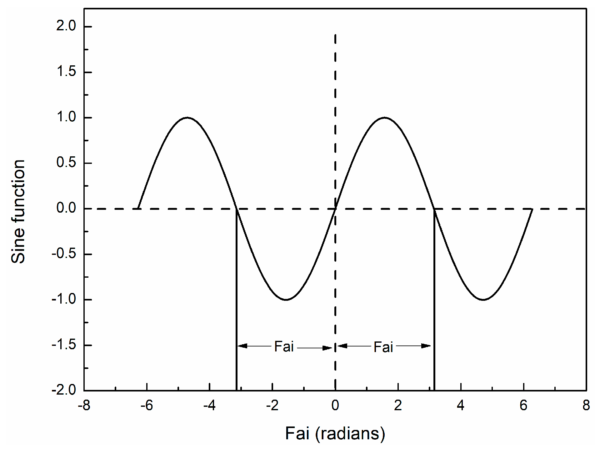
- The influence trend of roll profile parameters A and B on contact pressure between rolls and strip flatness is quite the opposite. Fai had a significant effect on controlling the quadric strip flatness.
- The roll profile parameters were optimized based on the NSGA-II, and the optimal roll profile parameters of 4.419, 0.004804, 78, and 1.396 are proposed for A, B, C, and Fai, respectively. The optimal roll profile parameters were applied to a 1740 mm six-high five stand tandem cold rolling mills, and the flatness quality was significantly improved.
Author Contributions
Funding
Acknowledgments
Conflicts of Interest
List of symbols
| yu | Third-order CVC upper roll profile |
| a, b, c, d | Coefficient of third-order CVC upper roll profile to be determined |
| x | Coordinate of the roll transverse units |
| ysu(x) | SmartCrown roll profile of upper roll |
| ysb(x) | SmartCrown roll profile of bottom roll |
| A, B, C, Fai | SmartCrown roll profile parameter to be determined |
| L | Length of the roll |
| s | Shifting distance of the rolls |
| ysu1(x) | SmartCrown roll profile of upper roll after shift |
| ysb1(x) | SmartCrown roll profile of bottom roll after shift |
| g(x) | Roll gap profile |
| Ce | Equivalent crown of the roll gap |
| Pi | Rolling force of unit i |
| Bs | Strip width |
| K | Deformation resistance of the strip |
| Tp | Influence coefficient of tension |
| Qp | External frictional stress state influence coefficient |
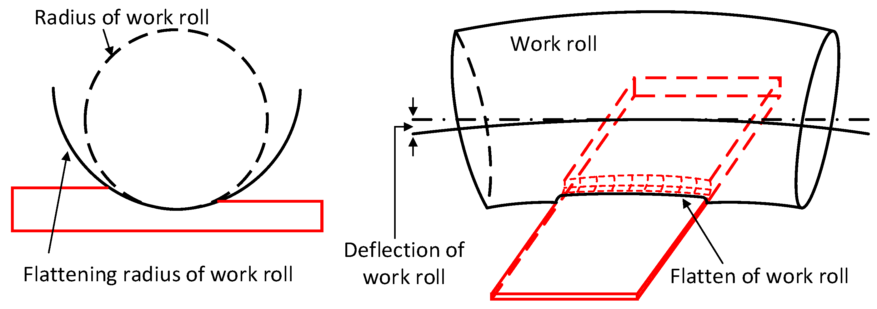
| R′ | Flattening radius of the work roll |
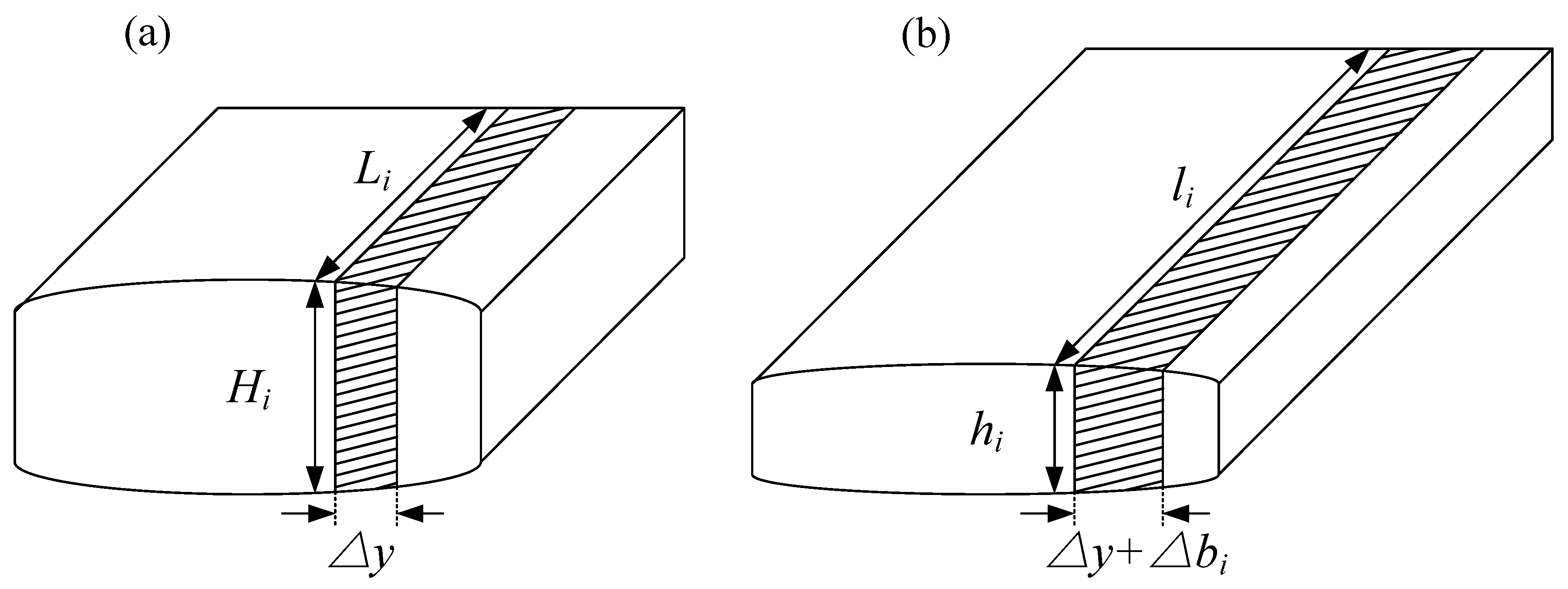
| Hi, △Hi | Entry strip thickness of unit i, incremental of entry strip thickness of unit i |
| hi, △hi | Exit strip thickness of unit i, incremental of exit strip thickness of unit i |
| tf, tb | Front and back tension |
| μ | Friction coefficient |
| qi | Contact pressure between work roll and intermediate roll of unit i |
| FWB, FIB | Work roll and intermediate roll bending force |
| RWN, RIN | Number of work roll and intermediate roll transverse unit |
| Qi | Contact pressure between intermediate roll and backup roll of unit i |
| YWi, YIi | Elastic deflection of work roll and intermediate roll |
| GW | Influence function matrix of work roll bending force |
| gw | Influence function of work roll bending force |
| YWIi | Flatten between work roll and intermediate roll |
| YWIL/2 | Flatten of the roll center |
| MIi, MWi | Profile of the intermediate roll and the work roll |
| DW, DI | Diameter of work roll and intermediate roll |
| EW, EI | Young’s modulus of work roll and intermediate roll |
| νW, νI | Poisson’ ratio of work roll and intermediate roll |
| GWI | Influence function matrix of roll flatten |
| gwi | Influence function of roll flatten |
| qci | Contact pressure between work roll and intermediate roll, which to be recalculated |
| m | Calculation times of contact pressure between work roll and intermediate roll |
| λ | Smoothing constant |
| ∑p | Total rolling force |
| ∑q | Total contact pressure between work roll and intermediate roll |
| ε | Accuracy requirement |
| hl/2 | Thickness in the center of the strip |
| YWSi | Work roll flatten caused by the rolling force |
| YWSL/2 | Work roll flatten caused by the rolling force in the center of the strip |
| Li, △Li | Entry strip length of unit i, incremental of entry strip length of unit i |
| li, △li | Exit strip length of unit i, incremental of exit strip length of unit i |
| △y | Strip width of unit i |
| △bi | Lateral spread of unit i |
| Average entry and exit strip length of all strip transverse units | |
| Average entry and exit strip thickness of all strip transverse units | |
| QWImax, QWImin | Maximum and minimum value of contact pressure between work roll and intermediate roll |
| J1max, J1min | Maximum and minimum values corresponding to the first objective |
| J2max, J2min | Maximum and minimum values corresponding to the second objective |
| α1, α2 | Weight coefficients of objective 1 and objective 2 |
References
- Abdelkhalek, S.; Montmitonnet, P.; Legrand, N.; Buessler, P. Coupled approach for flatness prediction in cold rolling of thin strip. Int. J. Mech. Sci. 2011, 53, 661–675. [Google Scholar] [CrossRef]
- Tran, D.; Tardif, N.; Limam, A. Experimental and numerical modeling of flatness defects in strip cold rolling. Int. J. Solids. Struct. 2015, 69–70, 343–349. [Google Scholar] [CrossRef]
- Zhao, J.; Wang, X.; Yuan, Q.; Wang, Q.; Liu, C.; Song, G. High precision shape model and presetting strategy for strip hot rolling. J. Mater. Process. Technol. 2019, 265, 99–111. [Google Scholar] [CrossRef]
- Wang, Q.; Li, X.; Hu, Y.; Sun, J.; Zhang, D. Numerical Analysis of Intermediate Roll Shifting–Induced Rigidity Characteristics of UCM Cold Rolling Mill. Steel. Res. Int. 2018, 89, 1700454. [Google Scholar] [CrossRef]
- Li, X.; Zhang, J.; Chen, X.; Cao, J.; Li, H. Improvement on strip flatness of cold temper mills by modifying roll contour shape. J. Univ. Sci. Technol. Beijing 2004, 11, 251–255. [Google Scholar]
- Wang, X.; Li, F.; Wang, L.; Zhang, X.; Dong, L. Development and application of roll contour configuration in temper rolling mill for hot rolled thin gauge steel strip. Ironmak. Steelmak. 2013, 39, 163–170. [Google Scholar] [CrossRef]
- He, H.; Liu, Y.; Yang, Q.; Wang, X.; Wang, S.; Wang, Q. Symmetry variable taper work roll technology for silicon steel profile control in hot strip mills. Ironmak. Steelmak. 2019. [Google Scholar] [CrossRef]
- Bald, W.; Beisemann, G.; Feldmann, H.; Schultes, T. Continuously variable crown (CVC) rolling. Iron Steel Eng. 1987, 64, 32–41. [Google Scholar]
- Bald, W.; Klamma, K. CVC technology for cold rolling mills-plant examples. Iron Steel Eng. 1988, 65, 24–28. [Google Scholar]
- He, A.; Kong, F.; Shao, J. Novel curved roll contour technology for profile control in hot strip mills. Ironmak. Steelmak. 2014, 42, 55–62. [Google Scholar] [CrossRef]
- Lu, C.; Tieu, A.; Jiang, Z. A design of a third-order CVC roll profile. J. Mater. Process. Technol. 2002, 125–126, 645–648. [Google Scholar] [CrossRef]
- Berger, S.; Hoen, K.; Hof, H.; Krämer, S.; Seidel, J.; Sudau, P. Evolution of CVC Plus® technology in hot rolling mills. Metall. Res. Technol. 2008, 105, 44–49. [Google Scholar] [CrossRef]
- Shao, J.; He, A.; Sun, W.; Yang, Q.; Guan, C.; Wang, Z. Research and application of VCR plus technology in hot strip mills. In Proceedings of the 2nd International Conference on Mechanic Automation and Control Engineering, Hohhot, China, 15–17 July 2011; pp. 5120–5123. [Google Scholar]
- Li, H.; Zhang, J.; Cao, J.; Meng, L. Analysis of crown control characteristics for SmartCrown work roll. Adv. Mater. Res. 2010, 156–157, 1261–1265. [Google Scholar] [CrossRef]
- Yang, G.; Cao, J.; Zhang, J.; Lu, H.; Jia, S.; Zeng, W. SmartCrown work roll contour of a 4-hi tandem cold rolling mill. J. Univ. Sci. Technol. Beijing 2006, 28, 669–671. [Google Scholar]
- Yang, G.; Cao, J.; Zhang, J.; Jia, S.; Tan, R. Backup roll contour of a SmartCrown tandem cold rolling mill. J. Univ. Sci. Technol. Beijing 2008, 15, 357–361. [Google Scholar] [CrossRef]
- Cao, J.; Chai, X.; Li, Y.; Kong, N.; Jia, S.; Zeng, W. Integrated design of roll contours for strip edge drop and crown control in tandem cold rolling mills. J. Mater. Process. Technol. 2018, 252, 432–439. [Google Scholar] [CrossRef]
- Wang, X.; Li, F.; Li, B.; Zhu, G.; Li, B.; Zhang, B. VCR back-up roll and negative work roll contour design for solving roll spalling and transfer bar profile problems in hot strip mill. Ironmak. Steelmak. 2013, 37, 633–640. [Google Scholar] [CrossRef]
- Deb, K.; Agrawal, S.; Pratap, A.; Meyarivan, T. A fast elitist non-dominated sorting genetic algorithm for multi-objective optimization: NSGA-II. Lect. Notes Comput. Sci. 2000, 1917, 849–858. [Google Scholar]
- Coello, C.; Becerra, R. Evolutionary multiobjective optimization in materials science and engineering. Mater. Manuf. Process. 2009, 24, 119–129. [Google Scholar] [CrossRef]


| Name | Value |
|---|---|
| Work roll diameter/length (mm) | 430/1740 |
| Intermediate roll diameter/length (mm) | 500/1990 |
| Backup roll diameter/length (mm) | 1310/1750 |
| Strip width (mm) | 1250 |
| Strip thickness before/after rolled (mm) | 2.3/1.7 |
| Material | DP780 |
| Front/back tension (MPa) | 140/110 |
| Work roll/intermediate roll bending force (kN) | 300/300 |
| Intermediate roll shifting (mm) | 0 |
© 2020 by the authors. Licensee MDPI, Basel, Switzerland. This article is an open access article distributed under the terms and conditions of the Creative Commons Attribution (CC BY) license (http://creativecommons.org/licenses/by/4.0/).
Share and Cite
Jin, X.; Li, C.-s.; Wang, Y.; Li, X.-g.; Gu, T.; Xiang, Y.-g. Multi-Objective Optimization of Intermediate Roll Profile for a 6-High Cold Rolling Mill. Metals 2020, 10, 287. https://doi.org/10.3390/met10020287
Jin X, Li C-s, Wang Y, Li X-g, Gu T, Xiang Y-g. Multi-Objective Optimization of Intermediate Roll Profile for a 6-High Cold Rolling Mill. Metals. 2020; 10(2):287. https://doi.org/10.3390/met10020287
Chicago/Turabian StyleJin, Xin, Chang-sheng Li, Yu Wang, Xiao-gang Li, Tian Gu, and Yong-guang Xiang. 2020. "Multi-Objective Optimization of Intermediate Roll Profile for a 6-High Cold Rolling Mill" Metals 10, no. 2: 287. https://doi.org/10.3390/met10020287
APA StyleJin, X., Li, C.-s., Wang, Y., Li, X.-g., Gu, T., & Xiang, Y.-g. (2020). Multi-Objective Optimization of Intermediate Roll Profile for a 6-High Cold Rolling Mill. Metals, 10(2), 287. https://doi.org/10.3390/met10020287