Article

Mechanical Properties, Thermal Stability and Microstructures of W-Re-ZrC Alloys Fabricated by Spark Plasma Sintering

1
Guangdong Provincial Key Laboratory of Advanced Welding Technology, Guangdong Welding Institute (China-Ukraine E.O. Paton Institute of Welding), Guangzhou 510650, China
2
Key Laboratory of Materials Physics, Institute of Solid State Physics, Chinese Academy of Sciences, Hefei 230031, China
*
Authors to whom correspondence should be addressed.
Metals 2020, 10(2), 277; https://doi.org/10.3390/met10020277
Submission received: 13 January 2020 / Revised: 13 February 2020 / Accepted: 14 February 2020 / Published: 20 February 2020

Abstract

:
Tungsten materials, used as friction stir welding tools, undergo severe plastic deformation and even collapse at high operating temperatures. In order to improve the low-temperature toughness and high-temperature strength, W-10wt.%Re-0.5wt.%ZrC alloys were processed by high-energy ball milling and subsequent spark plasma sintering. Single solid-solution W-Re powders with typical body-centered cubic structures were achieved when the milling time increases to 50 h. The microhardness, tensile properties, thermal stability and microstructures of this sintered W-10wt.%Re-0.5wt.%ZrC alloys were investigated. Synergetic effects of the solute Re and nanosized dispersion particles induce improvements in low-temperature toughness and high-temperature strength. The alloy suffers ductile fracture at 300 °C, which is about 400 °C and 300 °C lower than that of the spark plasma sintered pure W and W-0.5wt.%ZrC, respectively. Besides, this W-10wt.%Re-0.5wt.%ZrC has a high ultimate tensile strength of 818 MPa and uniform elongation of ~ 8.1% at 300 °C. Moreover, the microstructures and hardness remain stable even after 1500 °C anneal. Based on a detailed microstructure analysis, the mechanisms for the enhanced strength, low-temperature ductility and high thermal stability are proposed and discussed. Grain boundary mobility is impeded by the kinetics constraint through dispersed particles pinning and solute Re atoms dragging, which leads to improved thermal stability. The formation of Zr-C-O particles is most probably attributed to ZrC particles capturing and interacting with impurity oxygen during sintering.

1. Introduction

Friction stir welding (FSW) is a solid-state welding process using nonconsumable tools and has been successfully used in the joining of aluminum alloys with a low melting point. The application space for FSW will be greatly expanded when it can be widely used in the joining of materials with a higher melting point, e.g., steels and titanium alloys. Whereas a long-term operation for jointing at high softening temperatures, FSW tools undergo severe plastic deformation and even collapse at high temperatures above 900 °C [1,2], which can cause significant negative impacts on the jointing quality [3]. Therefore, tool materials should offer desirable comprehensive properties at elevated temperatures, including excellent high-temperature toughness, high microstructure stability and outstanding wear resistance [4]. Due to the high-temperature application and high durability, refractory metals—in particular, tungsten (W) materials—meet part of the requirements and have become main candidates for FSW tools [3,4,5,6,7]. However, the issues that inherent embrittlement and property degradation of tungsten materials during FSW still exist, impeding FSW use in high melting point material joints.
According to prior works, adding rhenium (Re) as a solute element is an effective toughening strategy for pure tungsten, which normally exhibits inherent brittleness and a relatively high ductile-brittle transition temperature (DBTT) [8,9]. Alloying Re atoms in W lattices leads to an increase in the number of available slip planes and a decreased stress level to initiate plastic deformation, resulting in a desirable ductility [10]. Moreover, the addition of Re increases the recrystallization temperature, which reflects alloying Re and can cause thermodynamic reduction to improve the microstructure stability [11]. Thus, the W-25%Re alloy has been synthesized and become the candidate material that can be processed as a tool for the FSW of steels [6]. However, the wear rate of tools made by W-25%Re is still high and will quickly degrade [1]. Meanwhile, W-25%Re tools have been reluctantly used for several years due to the high contents of Re and the rather expensive cost of Re [1,4].
Another effective approach that overcomes embrittlement and improves tensile strength at low temperatures is dispersing second-phase particles, e.g., oxide and carbide, in the tungsten matrix [12,13,14,15,16,17,18,19]. The oxide and carbide can refine grain size, resulting in an increased grain boundary (GB) volume and density. That is to say, the tendency of the contaminant (e.g., O, N and P) segregation at GBs is to some extent relieved, and thus, the GB cohesion could be strengthened and the embrittlement can be driven down [20,21]. With regard to increasing GB cohesion for improving the ductility, there have been a number of recent findings on the oxide/carbide dispersion strengthened W (ODS/CDS-W) alloys, which are commonly processed by sintering and, subsequently, hot deformation [18,19,22,23]. For example, ODS-W fabricated by powder metallurgy can (pressing, sintering and hot forging) achieve a favorable low-temperature ductility and fracture in a ductile manner approximately at 200 °C [12]. Based on the interface design, Xie et al. also reported that W-0.5wt.%ZrC alloy plates, processed by sintering and hot rolling, exhibit a flexural strength of 2.5 GPa and a strain of 3% at room temperature (RT) [18]. Similarly, nanograined W-1.1%TiC material fabricated through grain boundary sliding-based microstructural modification (GSMM) strategy exhibits a high fracture strength up to about 4.4 GPa and an appreciable flexural ductility at RT [13,23]. However, the fabrication procedure of this GSMM W-1.1%TiC is overcomplex, as well as the size of the final product is limited. A word of caution is in order here. Although the low-temperature ductility can be improved in the aforementioned ODS/CDS alloys to some extent, their applications for tool materials remain challenging. As an example, the high-temperature strength of the W-0.5wt.%ZrC alloy decreases from 991 MPa (RT) to 582 MPa (500 °C) [18]. Moreover, some large oxide or carbide particles located at GBs will trigger significant stress concentration and cracking, leading to a decrease in toughness [12].
Minor fractions of hafnium carbide (HfC), utilizing the synergy of solute element and oxide/carbide dispersions, have been added to fabricate W-Re-HfC alloys for FSW tools in order to improve the mechanical properties and thermal stability [1,4]. HfC addition improves high-temperature strength but sacrifices the toughness of tools, causing intergranular fracture after FSW. This intergranular failure was due to micron-sized particles located at GBs, resulting in crack initiation by stress concentration [24]. It is generally believed that particle size brings significant effects in mechanical and thermal properties. However, the potential synergy effects of solution elements and dispersions have not been completely exerted. The particle distribution impacts on the properties and microstructure stability of W-Re-based tools are few investigated and reported. These remaining issues deserve to be investigated in detail for the purpose of realizing the full potential of tungsten-based tools in applications.
In this work, the primary focus is to fabricate W-Re-ZrC alloys by mechanical alloying (MA) and subsequent spark plasma sintering (SPS) that can achieve fast densification at a relatively low temperature in a short time [16]. The MA powders for SPS are processed with a set of milling times (i.e., 5, 10, 20, 30, 40 and 50 h). Additionally, synergetic effects of the solute Re and nanosized dispersion particles on the microstructures, tensile properties and thermal stability of SPSed specimens are investigated.

2. Methods

2.1. W-Re-ZrC Alloy Powder Processing

W (~3 μm, purity > 99.9%); Re (~325 mesh, purity > 99.8%) and ZrC (~80 nm, purity > 99.5%) powders were used for the high-energy MA of W-10wt.% Re-0.5wt.% ZrC (WRZ) alloys. These mixed powders were milled for different times (i.e., from 5 to 50 h) in WC/Co vessels with WC/Co balls (8 mm in diameter) in an Ar-H2 (95:5) mixture atmosphere. The ball-to-powder ratio was 8:1, and the rotation speed was 350 rpm/min.

2.2. Consolidation via SPS

Powders were collected and divided into four different groups based on the corresponding milling time: 20, 30, 40 and 50 h. Powders were subjected into a mold and sintered into disc-shaped products with the dimension of about 20 mm in diameter and 1 mm in thickness, via SPS (Furnace SE-607, FCT Group, Rauenstein, Germany). The sintering program is shown in Figure 1. The pressure was maintained at 64 MPa (20 kN) during the whole sintering process. Notice that the SPSed specimens using four different groups of powders are labeled as materials A, B, C and D (see Table 1), respectively.

2.3. Microstructural Caracterization, Tensile Tests and Thermal Stability

Phase characteristic in these powders after different milling times was studied by powder X-ray diffraction patterns (XRD, X′pert Powder, Malvern Panalytical Ltd., Almelo, Netherlands). The powder morphology was observed by a field emission scanning electron microscope (SEM, Sirion200, Thermo Fisher Scientific Inc., Hillsboro, OR, USA). The metallography of SPSed specimens was obtained by an optical microscope (OM, AX10, Carl Zeiss AG, Oberkochen, Germany). Before the metallographic observation, the SPSed specimens were processed with several rounds of mechanical polishing, then etched using a solution comprised of 10% potassium ferricyanide and 10% sodium hydroxide aqueous solution. The average grain size of W was measured based on over 300 grains in different optical microscope graphs. A transmission electron microscope (TEM, JEM-2000FX, JEOL Ltd., Akishima, Japan) was used to study the microstructure and particle distribution of WRZ alloys. The energy-dispersive X-ray spectroscopy (EDS, INCA, Oxford Instruments plc, Abingdon, United Kingdom) installed respectively on the SEM and TEM was employed for elemental analysis. Vickers hardness was measured with a low-load hardness tester at a load of 200 N and at a constant indentor dwell time of 30 s. After indentation, the length of each of the two diagonals of the square-shaped Vickers indentation was immediately measured by optical microscopy with a magnification of 300 and an error of measurement of ±1 µm.
For tensile tests, all SPSed specimens were polished into a dog bone-shaped flat with a cross section of 1.5 × 0.75 mm2 and a gauge length of 5 mm, as shown in Refeence [15]. The tensile tests were carried out at various temperatures from room temperature (RT) to 700 °C in Ar atmosphere using an Instron-5967 universal testing machine (Instron, Norwood, MA, USA) at a constant speed of 0.1 mm/min. For thermal stability tests, these specimens were polished and then isochronally annealed at various temperatures ranging from 1300 °C to 1800 °C for 1 h in vacuum. The heating and cooling rates were all 10 °C/min during the heat treatments. Grain growth is a microstructural transformation as a function of the changed annealing temperature. The quantitative metallography analysis was adopted to describe the grain growth behaviors.

3. Results and Discussion

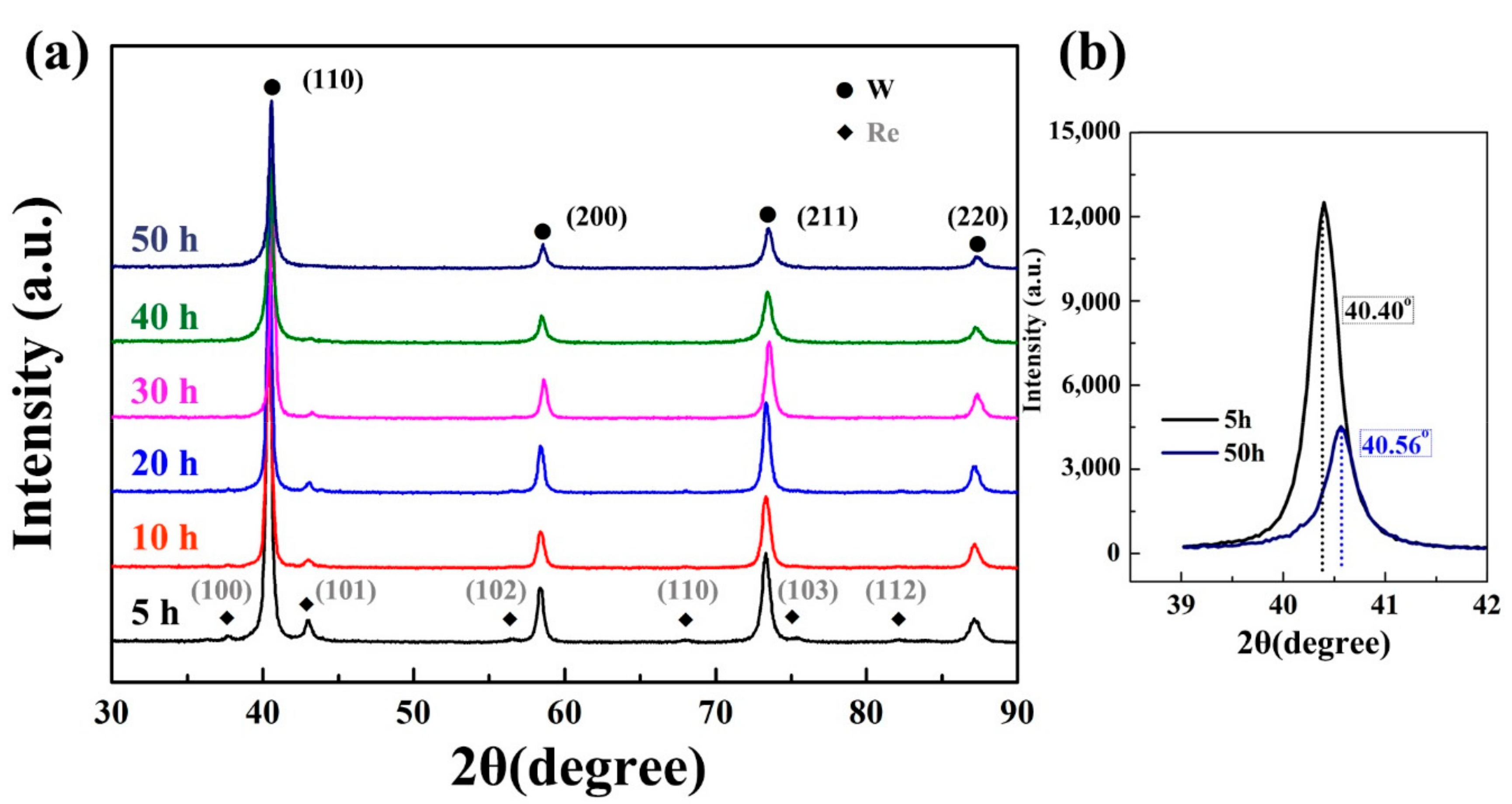
XRD patterns of WRZ powders at various milling times are shown in Figure 2. Both diffraction peaks of tungsten (W) and rhenium (Re) are indexed for 5-h milled powders. It is worth mentioning that diffraction peaks corresponding to ZrC are not detected due to the relatively low content of 0.5wt.%. As the milling time is less than 30 h, the hexagonal close-packed (HCP) structured Re is always detectable. The intensities of Re peaks decrease in a time-dependent manner as milling time increases to 40 h and 50 h, suggesting that Re atoms are dissolved into the W matrix. Furthermore, the peak position of the indexed W phase shifts to the high angle, resulting from a shrinking lattice of the W matrix. For example, the position of the (110) diffraction peaks of 5-h and 50-h milled powders shift from 40.40° to 40.56°, respectively, as shown in Figure 2b. The lattice contraction of the W matrix is attributed to smaller Re atoms (atomic radius:188 pm) replacing W atoms (atomic radius:193 pm) in their lattice positions. That is to say, a W(Re) solid solution is constructed after the high-energy MA, with a milling time up to 50 h, which can be further confirmed by the merely indexed diffraction peaks of the BCC-structured W(Re) and the absence of HCP-structured Re peaks. This W(Re) solid solution is also observed in the reported ball-milled W-Re materials [25,26].
Figure 3 shows the morphology of powders as a function of the milling time. After 10-h milling, some tungsten powders are changed from original polygon morphology, as indicated by the red arrows in Figure 3a, into flake shapes. With increasing milling times up to 30 h, more W powders are deformed into flake shapes under the effect of the impact force. Some particles weld together and form large sheet powders, as indicated by the selected yellow circles in Figure 3b. When the milling time increases to 40 h, more pieces of powders undergo fragmentation of fragile flakes due to work hardening and stress concentration [27,28]. The inclination to fracture predominates over squeezing, leading to more particles being refined instead of flattened. The WRZ powders milled for 50 h (see Figure 3d) finally exhibit a refined flake morphology, with an average diameter of 150–200 nm in the radial direction.
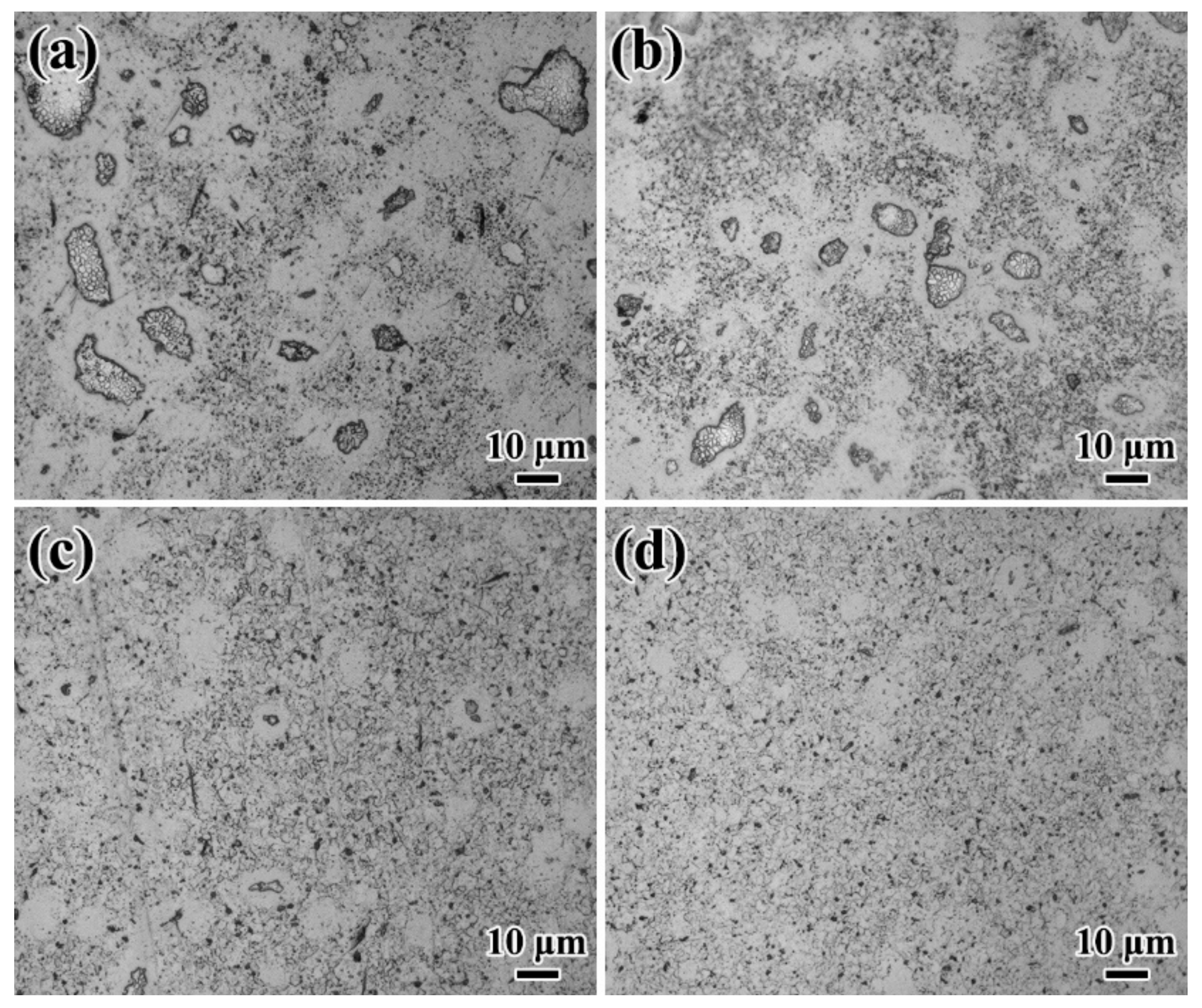
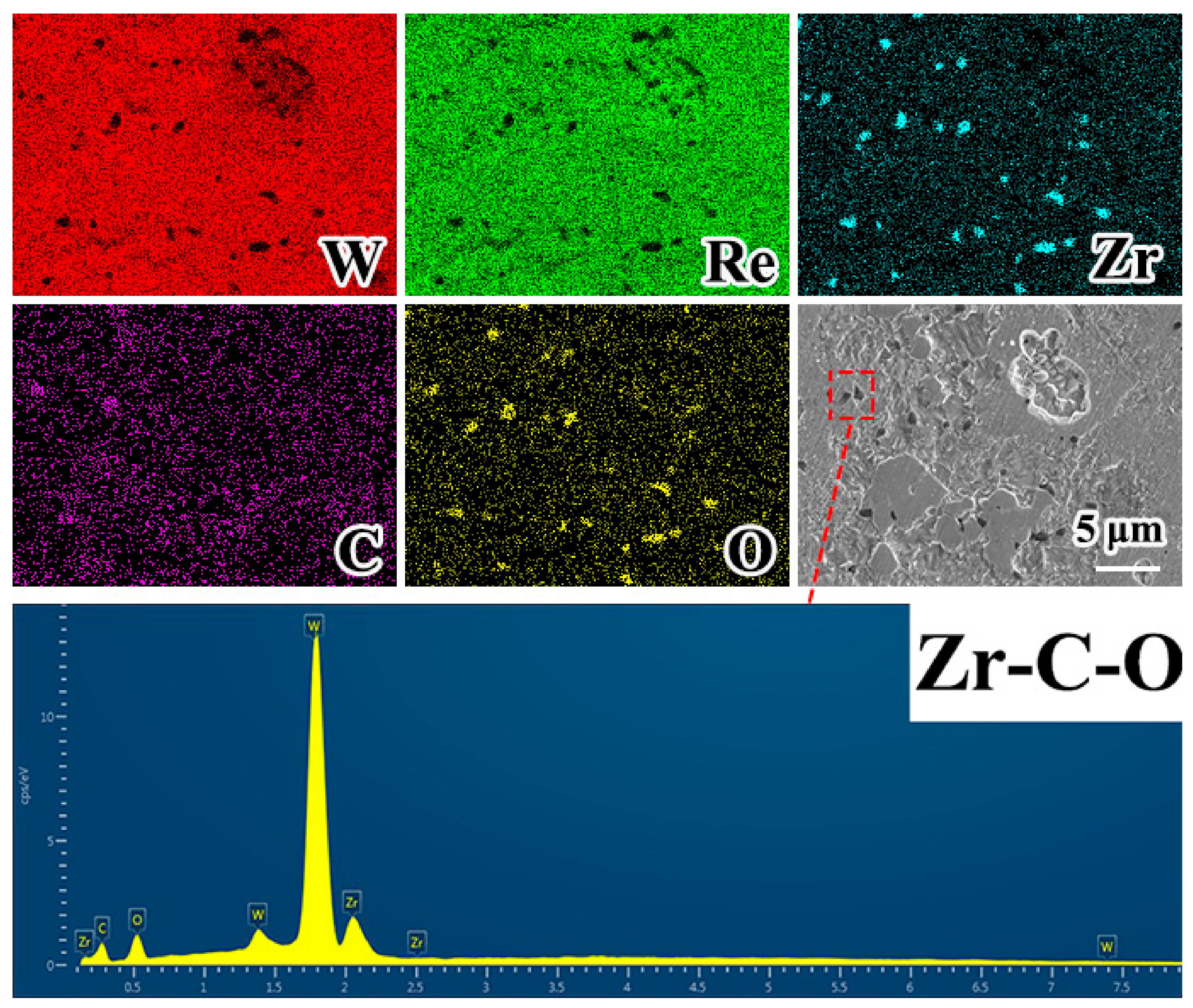
The density and the grain size of various SPSed specimens are listed in Table 1. The density increases with the milling time. Material D possesses the highest density of 19.12 g/cm3 among all four samples, along with a Vickers microhardness of 5.21 GPa, as shown in Table 1. The metallographic analysis for different samples were performed through the OM, as displayed in Figure 4. Obvious dark zones (in OM view) that consist of small grains are surrounded by the white zones without etching, as shown in Figure 4a–c. To confirm the element distribution, EDS line-scan (zone 1 in Figure 5) and mapping (Figure 6) analysis are conducted. EDS results of the obvious protrusion of Re signals along with weak W signals implies that Re is not completely dissolved due to the short milling time, and thus, retains the Re phase after sintering. The existence of the white zone (zone 2 in Figure 5) reveals that the Re signals are weaker as the areas are closer to the W matrix. The Re concentration in the white zones leads to the formation of the sigma phases due to the wide solubility [29,30]. For the material D (Figure 4d), the micron-sized dark zones are not observed, and the solid solution W phase with an average grain size of 2.53 μm coexists with a small amount of sigma phase. The small “black spot” marked by a red square in Figure 6 is identified as a Zr-C-O compound based on EDS mapping analysis. The formation of Zr-C-O particles is most probably attributed to ZrC particles capturing impurity oxygen during sintering. Due to the inevitably nonuniform particle distribution of ZrC during the milling process, the agglomeration of Zr-C-O particles is to some extent inevitable. The mechanism of the formation of such compounds will be discussed in the next section. The results analyzed through the metallographic images of the SPSed samples match well with those of the XRD results. The phases existing in powders can be inherited by the SPSed specimens. When the milling time is less than 40 h, Re phases are also obviously detected in the sintered materials A, B and C. When the milling time is up to 50 h, no Re phases can be found in material D. That is to say, SPS has limited effects on promoting alloying and solid solution because of the short sintering time (e.g., the holding time at 1300 °C, 1600 °C and 1800 °C is only 10, 15 and 5 min, respectively). Increased sintering and hold time could contribute to the formation of single-solid solution phases, whereas concurrent grain growth inevitably occurs as well. Therefore, alloying W-Re solid solution powders can ensure the bulk state, for example, of a single BCC structure within refined grains after SPS.
The engineering stress-strain curves of material D at various temperatures ranging from 300 to 700 °C are shown in Figure 7a. The ultimate tensile strength (UTS) and uniform elongation (UE) of the WRZ alloy (material D) and other reported W alloys tested at various temperatures are summarized in Figure 7b,c. The WRZ alloy shows typical brittle fractures at 200 °C with a UTS of 742 MPa. As the WRZ alloy tested at 300 °C, the UTS is as large as ∼ 818 MPa and the UE is ∼ 8.1%. With an increase in the tested temperature, the UTS slightly decreases by 2.3% to 799 MPa, 6.7% to 763 MPa, 10.5% to 732 MPa and 17.7% to 673 MPa for the specimens tested at 400 °C, 500 °C, 600 °C and 700 °C, respectively. In contrast, for other reported SPSed tungsten materials, such as pure W (W) [14], W-0.5wt.%ZrC (WZC) [17] and W-0.2wt.%Zr-1.0wt.%Y2O3 (WZY) [14], they all exhibit low strength and obvious brittle fractures below 500 °C. That is to say, the present WRZ alloy achieves a considerable plasticity in relatively low temperatures. The UST of WZY achieves the highest value of 610 MPa among the three reported samples at 500 °C. Meanwhile, all UTS values of WZR alloys (see Figure 7b) are higher than that of the aforementioned materials, which reflects that the solid solution strengthening of the Re addition can significantly improve high-temperature strength. However, the uniform elongation of the WRZ sample tested at 600 °C is 7.3%, which is only 30% of the UE value of the W-0.5wt.%ZrC-1wt.%Re (WRZC) [30] (see Figure 7c). This reduced elongation may come from undesirable brittle sigma phases, which will cause a loss of plasticity.
To explore the thermal stability of WRZ alloys, the evolutions of the microstructure and microhardness after annealing at various temperatures for 1 h are revealed, as shown in Figure 8. When the annealing temperature is up to 1500 °C, some grains are slightly grown, along with a hardness decrease from 5.21 GPa to 5.02 GPa. When the annealing temperature is increased to 1600 °C, obvious normal grain growth occurs, and the average grain size increases from the initial 2.53 μm to 3.54 μm. Meanwhile, the corresponding hardness decreases to 4.73 GPa. When the annealing temperature is further increased to 1800 °C, the hardness significantly decreases to 4.41 GPa, as quantified by the average grain size of 6.48 μm. Compared to the thermal stability SPSed WZC alloy [31], in which significant grain growth occurs after annealing at 1200 °C, extra Re addition can inhibit GBs mobility at elevated temperatures and naturally further increase the thermal stability. That is to say, the increased thermal stability of WRZ alloys is attributed to the combined effects of alloying Re and ZrC dispersions through the kinetics constraint of impeding GB migration [18,32].
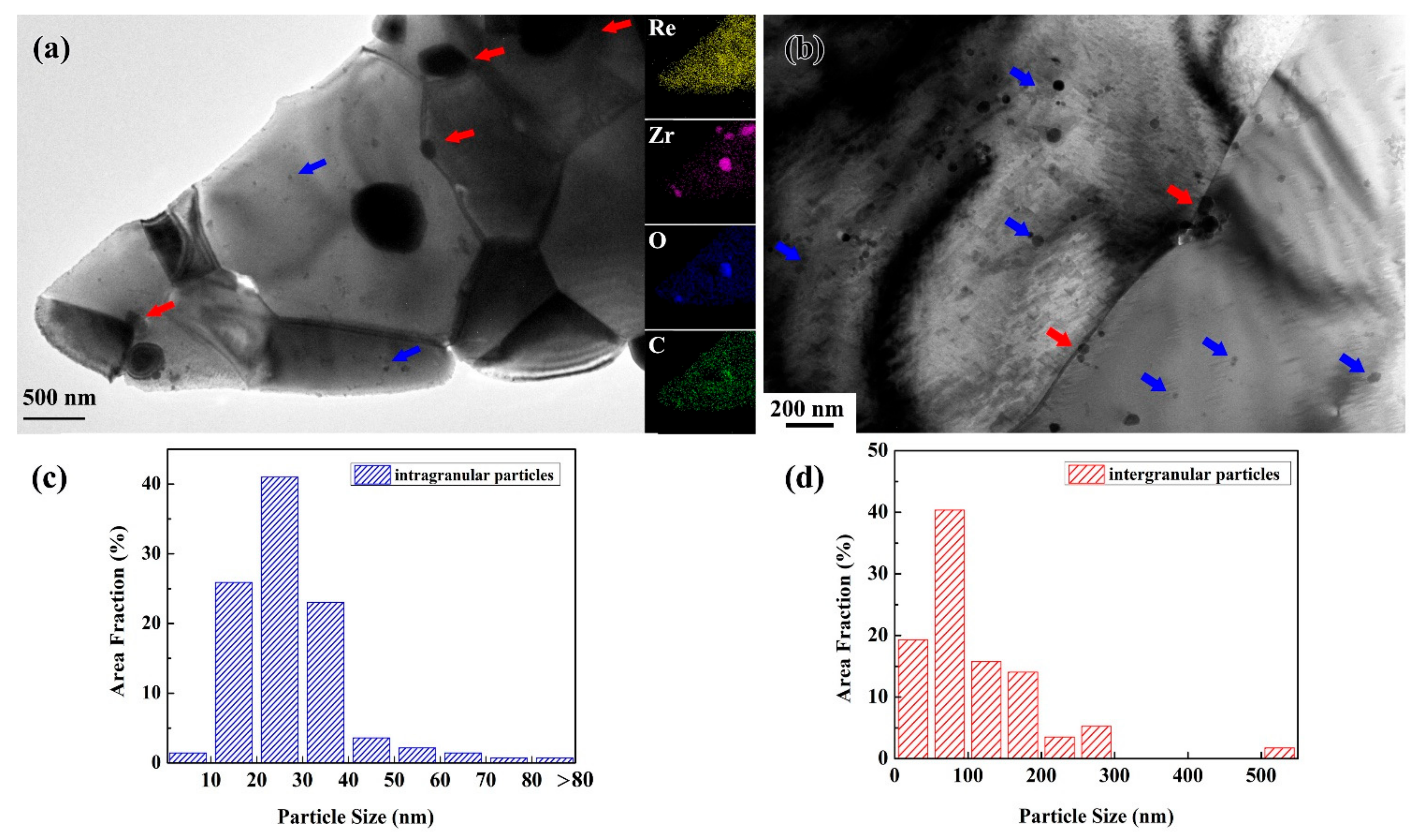
To reveal the influence of microstructures on such comprehensive properties, the microstructures of the WRZ alloy are characterized by TEM in detail, as displayed in Figure 9 and Figure 10. For WRZ alloys, most intragranular nanoscale particles are harmoniously dispersed in the grain interior, and minor ones are observed with large sizes at the submicron scale (see Figure 9a,b). The size of intragranular particles are in the range from 14.6 to 532.8 nm, with an average value of 47.8 nm (see Figure 9c). Meanwhile, the intergranular particles with an average value of 184.5 nm are obviously larger than that of the intragranular particles (see Figure 9d). The particles at the submicron scale are detected with the coexistence of Zr, C and O signals, which come from ZrC particles capturing impurity oxygen to form Zr-C-O compounds during sintering (see the inset in Figure 9a). The particle distribution implies that nanosized particles in the WRZ alloy are predominantly in the grain interior rather than at the grain boundaries. Intuitively, these dispersed particles in the grain interior could pin dislocations during deformation, and thus, strengthen WRZ alloys. Meanwhile, these structures also reveal enhanced kinetic constraints on GBs mobility as an aspect of thermal stability. EDS mapping images of the selected areas imply that Re is uniformly dissolved, resulting in an extensive solution strengthening, which reveals that solute Re dragging inhibits the GBs’ mobility, and thus, increases the microstructure stability. In addition, due to the high-energy MA and fast sintering, some severely deformed powders are fast consolidated into bulk pieces within the dislocation remaining, becoming another source to increase strength (see Figure 10a). High-resolution transmission electron microscopy (HRTEM) and the representative inverse fast Fourier transform (IFFT) images are employed to further clarify the phases of the selected two particles in Figure 10b. The HRTEM and corresponding IFFT images of the particle marked by a blue square show lattice fringes, with the distances of 0.281 nm and of 0.236 nm, match well with those of the (11-1) and (200) planes of the face-center cubic ZrC, respectively, as shown in Figure 10c. The HRTEM and IFFT images of the particle marked by the yellow square exhibits an approximate distance of 0.283 nm, which corresponds to that of the (111) and (1-11) planes of the ZrO2 phase with a monoclinic structure (PDF code: 01-072-1669), as shown in Figure 10d. Oxide formation is attributed to the high free oxygen concentration in powders and the interaction occurring between ZrC and oxygen during sintering [33,34]. Ball milling inevitably brings the indraught of impurity oxygen in powders [27], which is influential to GB embrittlement [13,23]. It has been recognized that the brittle fracture in W mainly occurs along GBs, as a consequence of the GBs weakening induced by the impurity (e.g., N and O) segregation at the GBs [13,21]. The nanosized carbide added in MA can capture the deleterious impurities, e.g., oxygen, segregated at GBs, contributing to the high improvement in low-temperature toughness and strength of tungsten. On the other hand, the forming stable particles at GBs are effective to strengthen GBs’ cohesion, since these intergranular particles work like a doorbolt locking GBs. Yet, note that the submicron-sized particles located at GBs will trigger a significant stress concentration, causing interfacial decohesion or particle cracking upon loading. Therefore, to develop the W alloy having a superior strength-ductility synergy, the particle size and distribution should be carefully tailored in a more controllable manner, which deserves to be investigated in depth in future works.

4. Conclusions

W-10wt.% Re-0.5wt.% ZrC alloys are fabricated by high-energy MA and subsequent SPS. The 50-h milled powders exhibit a single BCC structured solid-solution phase with an average particle diameter of 150 ~ 200 nm. WRZ alloys exhibit a high UTS of 818 MPa, along with a UE of 8.1% at 300 °C. The UTS slightly decreases by 17.7% to 673 MPa at 700 °C. Improvements in high-temperature strength and low-temperature toughness are attributed to the synergetic effects of the alloying Re and doping nanosized dispersions with an average size of 47.8 nm, both of which can pin down dislocations and GBs during deformation. Based on the microstructure evaluation, carbide particles capture impurity oxygen, indraught from long-term MA, to form Zr-C-O compounds. This strategy can offer another source to increase tensile strength, but ductility sacrifice also exists due to the formation of submicron-scale particles which tend to decohesion at a limit strain. As an aspect for thermal stability, WRZ alloys can keep grain stabilization when the annealing temperature is up to 1500 °C, which is also resulted from synergetic effects. Alloying Re causes the thermodynamic reduction of the driving forces for grain coarsening. Meanwhile, nanosized dispersions, uniformly distributed in the grain interior and at GBs, can inhibit GB mobility through kinetic constraints.

Author Contributions

Conceptualization, S.M. and Y.Z.; investigation, S.M., Z.X., Y.L. and J.T.; writing—original draft, S.M. and writing—review and editing, S.M., Y.L., Y.Z. and Q.F. All authors have read and agreed to the published version of the manuscript.

Funding

This research was funded by the GDAS’ Special Fund Projects of the Construction of the Domestic First-Class Research Organization (2019GDASYL-0103076) and Talent Introduction (2016GDASRC-0203), the Key Areas Research and Development Program of Guangdong Province (2019B090921003) and the Science and Technology Plan Project of Guangzhou City (201704030038 and 201807010068).

Acknowledgments

The authors would also like to thank the Analysis and Testing Center of the Institute of Solid State Physics, Chinese Academy of Sciences.

Conflicts of Interest

The authors declare no conflict of interest.

References

  1. Liu, F.C.; Hovanski, Y.; Miles, M.P.; Sorensen, C.D.; Nelson, T.W. A review of friction stir welding of steels: Tool, material flow, microstructure, and properties. J. Mater. Sci. Technol. 2018, 34, 39–57. [Google Scholar] [CrossRef]
  2. Mishra, R.S.; Ma, Z.Y. Friction stir welding and processing. Mater. Sci. Eng. R Rep. 2005, 50, 1–78. [Google Scholar] [CrossRef]
  3. Prado, R.A.; Murr, L.E.; Soto, K.F.; McClure, J.C. Self-optimization in tool wear for friction-stir welding of Al 6061 + 20% Al2O3 MMC. Mater. Sci. Eng. A 2003, 349, 156–165. [Google Scholar] [CrossRef]
  4. Thompson, B.T. Tool Degradation Characterization in the Friction Stir Welding of Hard Metals. Ph.D. Thesis, The Ohio State University, Columbus, OH, USA, 2010. [Google Scholar]
  5. Rai, R.; De, A.; Bhadeshia, H.K.D.H.; DebRoy, T. Review: Friction stir welding tools. Sci. Technol. Weld. Join. 2011, 16, 325–342. [Google Scholar] [CrossRef]
  6. Weinberger, T.; Enzinger, N.; Cerjak, H. Microstructural and mechanical characterisation of friction stir welded 15-5PH steel. Sci. Technol. Weld. Join. 2009, 14, 210–215. [Google Scholar] [CrossRef]
  7. Reynolds, A.P.; Hood, E.; Tang, W. Texture in friction stir welds of Timetal 21S. Scr. Mater. 2005, 52, 491–494. [Google Scholar] [CrossRef]
  8. Klopp, W.D.; Raffo, P.L.; Witzke, W.R. Mechanical Properties of Dilute Tungsten-Rhenium Alloys; NASA: Washington, DC, USA, 1966. [Google Scholar]
  9. Geach, G.; Hughes, J. The alloys of rhenium with molybdenum or with tungsten and having good high temperature properties. In Plansee Proceeding; Pergamon Press: London, UK, 1955; pp. 245–253. [Google Scholar]
  10. Romaner, L.; Ambrosch-Draxl, C.; Pippan, R. Effect of Rhenium on the Dislocation Core Structure in Tungsten. Phys. Rev. Lett. 2010, 104, 195503. [Google Scholar] [CrossRef] [PubMed]
  11. Savitskii, E.M.; Tylkina, M.A.; Ipatova, S.I.; Pavlova, E.I. Properties of tungsten-rhenium alloys. Met. Sci. Heat Treat. Met. 1960, 2, 483–486. [Google Scholar] [CrossRef]
  12. Battabyal, M.; Schäublin, R.; Spätig, P.; Baluc, N. W–2wt.%Y2O3 composite: Microstructure and mechanical properties. Mater. Sci. Eng. A 2012, 538, 53–57. [Google Scholar] [CrossRef]
  13. Kurishita, H.; Matsuo, S.; Arakawa, H.; Sakamoto, T.; Kobayashi, S.; Nakai, K.; Okano, H.; Watanabe, H.; Yoshida, N.; Torikai, Y.; et al. Current status of nanostructured tungsten-based materials development. Phys. Scr. 2014, T159, 014032. [Google Scholar] [CrossRef]
  14. Liu, R.; Xie, Z.M.; Hao, T.; Zhou, Y.; Wang, X.P.; Fang, Q.F.; Liu, C.S. Fabricating high performance tungsten alloys through zirconium micro-alloying and nano-sized yttria dispersion strengthening. J. Nucl. Mater. 2014, 451, 35–39. [Google Scholar] [CrossRef]
  15. Miao, S.; Xie, Z.M.; Yang, X.D.; Liu, R.; Gao, R.; Zhang, T.; Wang, X.P.; Fang, Q.F.; Liu, C.S.; Luo, G.N.; et al. Effect of hot rolling and annealing on the mechanical properties and thermal conductivity of W-0.5wt.% TaC alloys. Int. J. Refract. Met. Hard Mater. 2016, 56, 8–17. [Google Scholar] [CrossRef]
  16. Wang, R.; Xie, Z.M.; Wang, Y.K.; Song, J.P.; Fang, Q.F.; Liu, R.; Jiang, Y.; Yang, J.F.; Zhang, T.; Wang, X.P.; et al. Fabrication and characterization of nanocrystalline ODS-W via a dissolution-precipitation process. Int. J. Refract. Met. Hard Mater. 2019, 80, 104–113. [Google Scholar] [CrossRef]
  17. Xie, Z.; Liu, R.; Fang, Q.; Zhang, T.; Jiang, Y.; Wang, X.; Liu, C. Microstructure and Mechanical Properties of Nano-Size Zirconium Carbide Dispersion Strengthened Tungsten Alloys Fabricated by Spark Plasma Sintering Method. Plasma Sci. Technol. 2015, 17, 1066–1071. [Google Scholar] [CrossRef] [Green Version]
  18. Xie, Z.M.; Liu, R.; Miao, S.; Yang, X.D.; Zhang, T.; Wang, X.P.; Fang, Q.F.; Liu, C.S.; Luo, G.N.; Lian, Y.Y.; et al. Extraordinary high ductility/strength of the interface designed bulk W-ZrC alloy plate at relatively low temperature. Sci. Rep. 2015, 5, 16014. [Google Scholar] [CrossRef]
  19. Zhao, M.; Zhou, Z.; Zhong, M.; Tan, J. Effect of hot rolling on the microstructure and fracture behavior of a bulk fine-grained W–Y2O3 alloy. Mater. Sci. Eng. A 2015, 646, 19–24. [Google Scholar] [CrossRef]
  20. Barbour, J.P.; Charbonnier, F.M.; Dolan, W.W.; Dyke, W.P.; Martin, E.E.; Trolan, J.K. Determination of the Surface Tension and Surface Migration Constants for Tungsten. Phys. Rev. 1960, 117, 1452–1459. [Google Scholar] [CrossRef]
  21. Tran Huu, L.; Morniroli, J.P.; Gantois, M.; Lahaye, M. Brittle fracture of polycrystalline tungsten. J. Mater. Sci. 1985, 20, 199–206. [Google Scholar] [CrossRef]
  22. Zhao, M.; Zhou, Z.; Ding, Q.; Zhong, M.; Arshad, K. Effect of rare earth elements on the consolidation behavior and microstructure of tungsten alloys. Int. J. Refract. Met. Hard Mater. 2015, 48, 19–23. [Google Scholar] [CrossRef]
  23. Ishijima, Y.; Kannari, S.; Kurishita, H.; Hasegawa, M.; Hiraoka, Y.; Takida, T.; Takebe, K. Processing of fine-grained W materials without detrimental phases and their mechanical properties at 200–432K. Mater. Sci. Eng. A 2008, 473, 7–15. [Google Scholar] [CrossRef]
  24. Liu, G.; Zhang, G.J.; Jiang, F.; Ding, X.D.; Sun, Y.J.; Sun, J.; Ma, E. Nanostructured high-strength molybdenum alloys with unprecedented tensile ductility. Nat. Mater. 2013, 12, 344–350. [Google Scholar] [CrossRef] [PubMed]
  25. Neikov, O.D. Chapter 3—Mechanical Alloying. In Handbook of Non-Ferrous Metal Powders, 2nd ed.; Neikov, O.D., Naboychenko, S.S., Yefimov, N.A., Eds.; Elsevier: Oxford, UK, 2019; pp. 91–124. [Google Scholar]
  26. Suryanarayana, C. Recent advances in the synthesis of alloy phases by mechanical alloying/milling. Met. Mater. 1996, 2, 195–209. [Google Scholar] [CrossRef]
  27. Suryanarayana, C. Mechanical alloying and milling. Prog. Mater Sci. 2001, 46, 1–184. [Google Scholar] [CrossRef]
  28. Ivanov, E.Y.; Suryanarayana, C.; Bryskin, B.D. Synthesis of a nanocrystalline W–25 wt.% Re alloy by mechanical alloying. Mater. Sci. Eng. A 1998, 251, 255–261. [Google Scholar] [CrossRef]
  29. Leonhardt, T. Properties of tungsten-rhenium and tungsten-rhenium with hafnium carbide. JOM 2009, 61, 68–71. [Google Scholar] [CrossRef]
  30. Yang, X.D.; Xie, Z.M.; Miao, S.; Liu, R.; Jiang, W.B.; Zhang, T.; Wang, X.P.; Fang, Q.F.; Liu, C.S.; Luo, G.N.; et al. Tungsten-zirconium carbide-rhenium alloys with extraordinary thermal stability. Fusion Eng. Des. 2016, 106, 56–62. [Google Scholar] [CrossRef]
  31. Xie, Z.M.; Zhang, T.; Liu, R.; Fang, Q.F.; Miao, S.; Wang, X.P.; Liu, C.S. Grain growth behavior and mechanical properties of zirconium micro-alloyed and nano-size zirconium carbide dispersion strengthened tungsten alloys. Int. J. Refract. Met. Hard Mater. 2015, 51, 180–187. [Google Scholar] [CrossRef]
  32. Humphreys, F.J.; Hatherly, M. Chapter 5—The Mobility and Migration of Boundaries. In Recrystallization and Related Annealing Phenomena, 2nd ed.; Humphreys, F.J., Hatherly, M., Eds.; Elsevier: Oxford, UK, 2004; pp. 121–167. [Google Scholar]
  33. Rama Rao, G.A.; Venugopal, V. Kinetics and mechanism of the oxidation of ZrC. J. Alloys Compd. 1994, 206, 237–242. [Google Scholar] [CrossRef]
  34. Katoh, Y.; Vasudevamurthy, G.; Nozawa, T.; Snead, L.L. Properties of zirconium carbide for nuclear fuel applications. J. Nucl. Mater. 2013, 441, 718–742. [Google Scholar] [CrossRef]
Figure 1. The temperature profile of the spark plasma sintering (SPS) process.
Metals 10 00277 g001
Figure 2. (a) X-ray diffraction (XRD) patterns of milled W-10wt.% Re-0.5wt.% ZrC (WRZ) powders as a function of milling time. (b) The (110) diffraction peaks of 5-h milled and 50-h milled WRZ powders.
Metals 10 00277 g002
Figure 3. SEM images of the 10-h milled powders (a), 30-h milled powders (b), 40-h milled powders (c) and 50-h milled powders (d).
Metals 10 00277 g003
Figure 4. Optical micrograph images of the spark plasma sinter (SPS)ed WRZ: material A (a), material B (b), material C (c) and material D (d).
Metals 10 00277 g004
Figure 5. Energy-dispersive X-ray spectroscopy (EDS)-line scan analysis showing the profile of tungsten and rhenium elements on the etched surface of WRZ alloys (material A).
Metals 10 00277 g005
Figure 6. EDS analysis of the surface of WRZ alloys (material A).
Metals 10 00277 g006
Figure 7. Tensile behavior (a) of a SPSed WRZ (material D), the ultimate tensile strength (UTS) (b) and uniform elongation (UE) (c) of SPSed W, WRZ, W-0.5wt.%ZrC (WZC), W-0.2wt.%Zr-1.0wt.%Y2O3 (WZY) and W-0.5wt.%ZrC-1wt.%Re (WRZC).
Metals 10 00277 g007
Figure 8. Optical micrograph images of as-sintered material D samples (a), annealed samples at 1500 °C (b), 1600 °C (c), 1700 °C (d), 1800 °C (e) and the average grain size and hardness (f) of annealed material D samples at various temperatures.
Metals 10 00277 g008
Figure 9. Transmission electron microscope (TEM) micrographs (a) and (b) of the material D sample and size distributions of intragranular (c) and intergranular (d) particles.
Metals 10 00277 g009
Figure 10. The TEM image of dislocation remaining of the material D sample after fast sintering (a), selected particles (b) and the high-resolution (HR)TEM and inset inverse fast Fourier transform (IFFT) (selected areas as indicated by arrows) images of corresponding particles in the blue circle (c) and in the yellow circle (d), respectively.
Metals 10 00277 g010
Table 1. Milling time, density, microhardness and grain size of W-10wt.% Re-0.5wt.% ZrC (WRZ) materials A, B, C and D, respectively.
SpecimensMilling Time (h)Density (g/cm3)Hardness (GPa)Grain Size (μm)
Material A2018.96 ± 0.014.87 ± 0.16-
Material B3019.02 ± 0.035.06 ± 0.18-
Material C4019.08 ± 0.035.15 ± 0.112.91 ± 0.24
Material D5019.12 ± 0.025.21 ± 0.062.53 ± 0.17