CMT-Based Wire Arc Additive Manufacturing Using 316L Stainless Steel: Effect of Heat Accumulation on the Multi-Layer Deposits


Abstract
1. Introduction
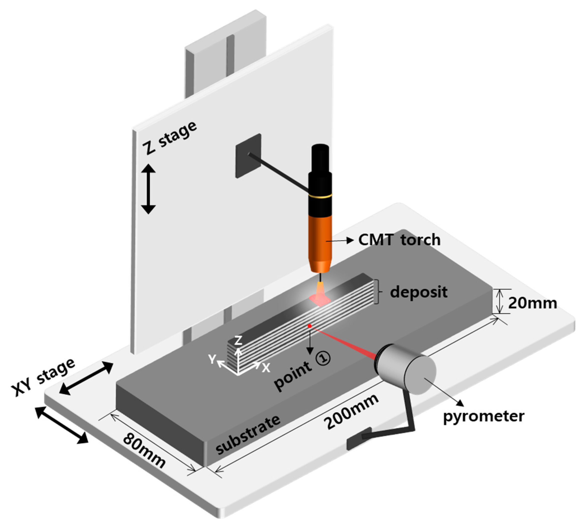
2. Experimental Setup
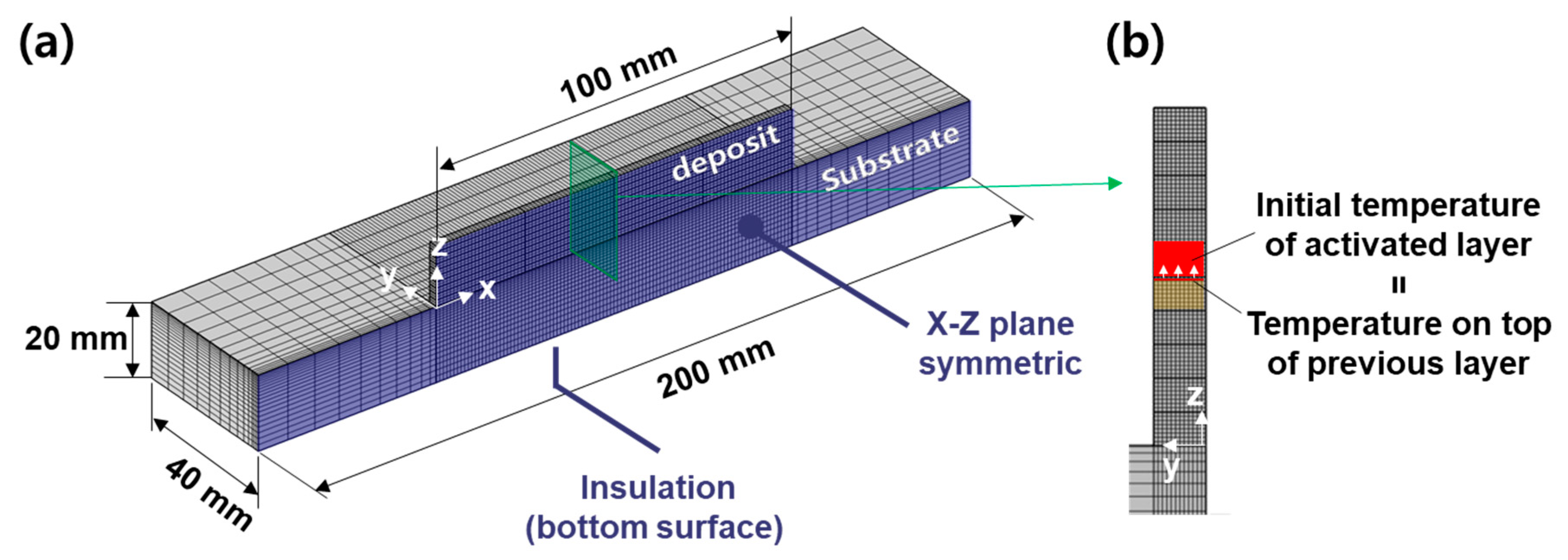
3. Finite Element Model
4. Results and Discussion
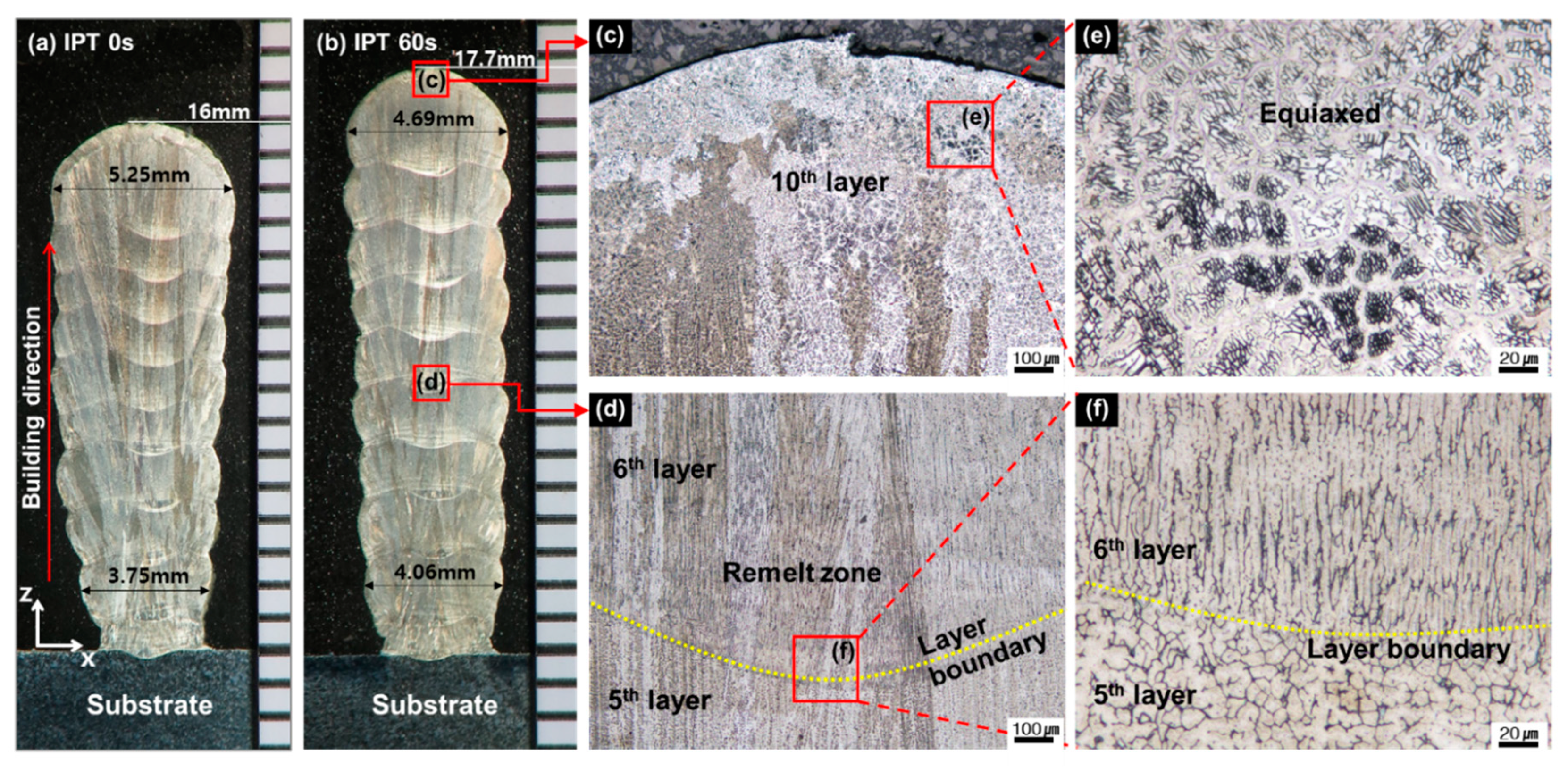
4.1. Microstructures
4.2. Experimental Validation Using the Numerical Model
5. Conclusions
- (1)
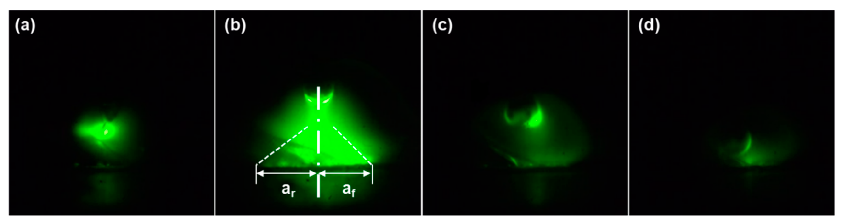
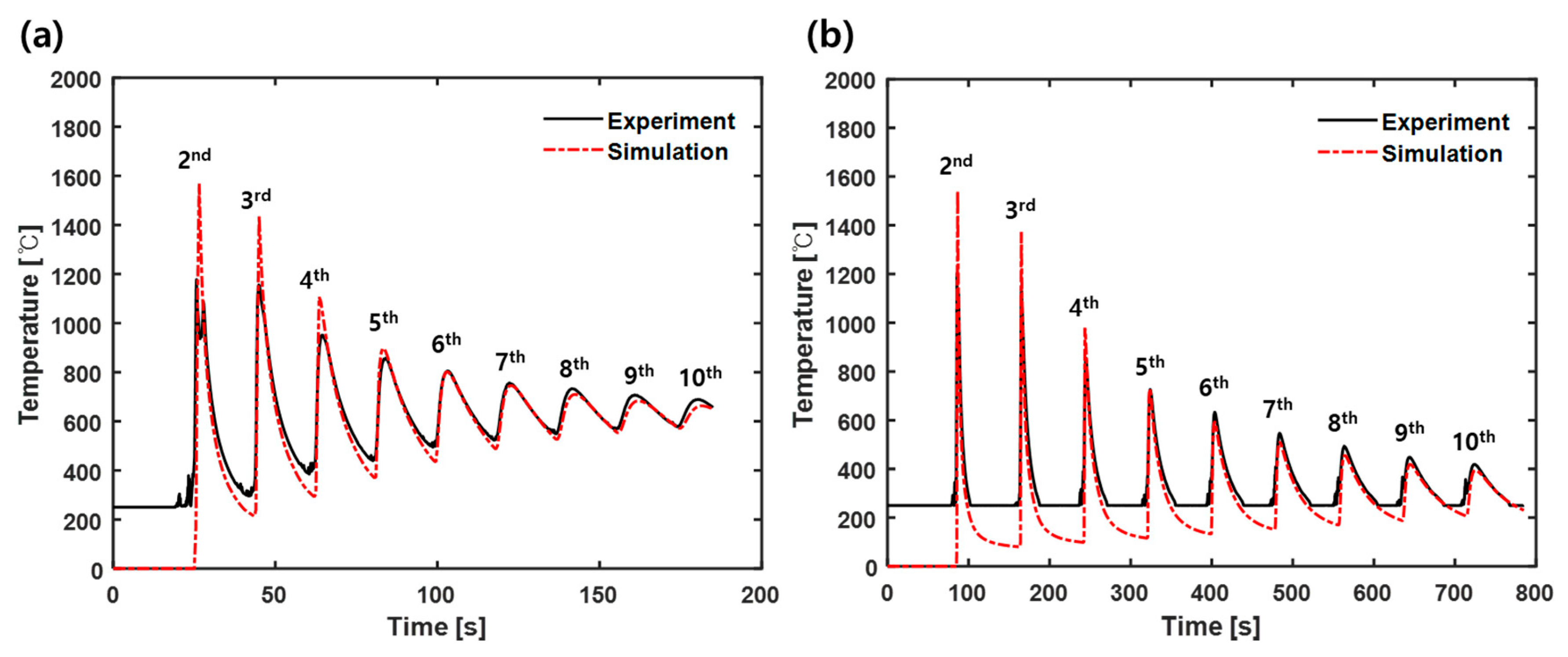
- The numerical model which is appropriate for WAMM was developed considering the characteristics of the CMT heat source for the first time. Using a high-speed camera, the transient behavior of the CMT arc was investigated, and this behavior was taken into account for the heat source of the numerical model. For the light model, considering practical applications, a domain-activation method was firstly adopted to analyze the effect of mass flow in the WAMM. In addition, a ND filter was used to adjust the brightness of the arc and the adjusted brightness was used for the realistic value of Goldak’s model. As a result, during cooling after depositions, the simulated and measured temperature show almost identical profiles except the peak temperatures with about 8% error. This work can directly be applied to various shapes of deposits for the thermal analysis.
- (2)
- Macro and micro characteristics of the deposits were comprehensively investigated. Especially, IPT was considered for the analysis of the heat accumulation during the multi-layer depositions. When a new layer was deposited over the top(previous) layer, due to the differences in the preheating temperature of the previous layer depending on IPT, approximately 45–60% of the top layer was found to be re-melt. In addition, the measured and simulated SDAS of the deposits were compared to investigate the heat accumulation. As a result, the equation regarding the SDAS size and the cooling rate was found to be more accurate over cooling rate of 50 K/s. From this result, mechanical properties such as hardness and yield strength in the WAMM can be anticipated to predict.
Funding
Conflicts of Interest
References
- Lee, Y.; Kirka, M.M.; Dinwiddie, R.B.; Raghavan, N.; Turner, J.; Dehoff, R.R.; Babu, S.S. Role of scan strategies on thermal gradient and solidification rate in electron beam powder bed fusion. Addit. Manuf. 2018, 22, 516–527. [Google Scholar] [CrossRef]
- Chen, X.; Li, J.; Cheng, X.; Wang, H.; Huang, Z. Effect of heat treatment on microstructure, mechanical and corrosion properties of austenitic stainless steel 316L using arc additive manufacturing. Mater. Sci. Eng. A 2018, 715, 307–314. [Google Scholar] [CrossRef]
- Biswal, R.; Zhang, X.; Syed, A.K.; Awd, M.; Ding, J.; Walther, F.; Williams, S. Criticality of porosity defects on the fatigue performance of wire+ arc additive manufactured titanium alloy. Int. J. Fatigue 2019, 122, 208–217. [Google Scholar] [CrossRef]
- Szost, B.A.; Terzi, S.; Martina, F.; Boisselier, D.; Prytuliak, A.; Pirling, T.; Hofmann, M.; Jarvis, D.J. A comparative study of additive manufacturing techniques: Residual stress and microstructural analysis of CLAD and WAAM printed Ti–6Al–4V components. Mater. Des. 2016, 89, 559–567. [Google Scholar] [CrossRef]
- Ziętala, M.; Durejko, T.; Polański, M.; Kunce, I.; Płociński, T.; Zieliński, W.; Łazińska, M.; Stępniowski, W.; Czujko, T.; Kurzydłowski, K.J. The microstructure, mechanical properties and corrosion resistance of 316 L stainless steel fabricated using laser engineered net shaping. Mater. Sci. Eng. A 2016, 677, 1–10. [Google Scholar] [CrossRef]
- Wu, B.; Pan, Z.; Ding, D.; Cuiuri, D.; Li, H. Effects of heat accumulation on microstructure and mechanical properties of Ti6Al4V alloy deposited by wire arc additive manufacturing. Addit. Manuf. 2018, 23, 151–160. [Google Scholar] [CrossRef]
- Ge, J.; Lin, J.; Lei, Y.; Fu, H. Location-related thermal history, microstructure, and mechanical properties of arc additively manufactured 2Cr13 steel using cold metal transfer welding. Mater. Sci. Eng. A 2018, 715, 144–153. [Google Scholar] [CrossRef]
- Asala, G.; Khan, A.K.; Andersson, J.; Ojo, O.A. Microstructural Analyses of ATI 718Plus® Produced by Wire-ARC Additive Manufacturing Process. Metall. Mater. Trans. A 2017, 48, 4211–4228. [Google Scholar] [CrossRef]
- Kou, S. Welding Metallurgy; Wiley: Hoboken, NJ, USA, 2003. [Google Scholar]
- Huang, Y.; Ansari, M.; Asgari, H.; Farshidianfar, M.H.; Sarker, D.; Khamesee, M.B.; Toyserkani, E. Rapid prediction of real-time thermal characteristics, solidification parameters and microstructure in laser directed energy deposition (powder-fed additive manufacturing). J. Mater. Process. Technol. 2019, 274, 116286. [Google Scholar] [CrossRef]
- Hejripour, F.; Binesh, F.; Hebel, M.; Aidun, D.K. Thermal modeling and characterization of wire arc additive manufactured duplex stainless steel. J. Mater. Process. Technol. 2019, 272, 58–71. [Google Scholar] [CrossRef]
- Xiong, J.; Li, R.; Lei, Y.; Chen, H. Heat propagation of circular thin-walled parts fabricated in additive manufacturing using gas metal arc welding. J. Mater. Process. Technol. 2018, 251, 12–19. [Google Scholar] [CrossRef]
- Jayanath, S.; Achuthan, A. A Computationally Efficient Hybrid Model for Simulating the Additive Manufacturing Process of Metals. Int. J. Mech. Sci. 2019, 160, 255–269. [Google Scholar] [CrossRef]
- Setien, I.; Chiumenti, M.; van der Veen, S.; San Sebastian, M.; Garciandía, F.; Echeverría, A. Empirical methodology to determine inherent strains in additive manufacturing. Comput. Math. Appl. 2019, 78, 2282–2295. [Google Scholar] [CrossRef]
- Ding, J.; Colegrove, P.; Mehnen, J.; Ganguly, S.; Almeida, P.S.; Wang, F.; Williams, S. Thermo-mechanical analysis of wire and arc additive layer manufacturing process on large multi-layer parts. Comput. Mater. Sci. 2011, 50, 3315–3322. [Google Scholar] [CrossRef]
- Goldak, J.; Chakravarti, A.; Bibby, M. A new finite element model for welding heat sources. Metall. Trans. B 1984, 15, 299–305. [Google Scholar] [CrossRef]
- Oyama, K.; Diplas, S.; M’hamdi, M.; Gunnæs, A.E.; Azar, A.S. Heat source management in wire-arc additive manufacturing process for Al-Mg and Al-Si alloys. Addit. Manuf. 2019, 26, 180–192. [Google Scholar] [CrossRef]
- Wu, Q.; Mukherjee, T.; Liu, C.; Lu, J.; DebRoy, T. Residual stresses and distortion in the patterned printing of titanium and nickel alloys. Addit. Manuf. 2019, 29, 100808. [Google Scholar] [CrossRef]
- Schaeffler, A.L. Constitution diagram for stainless steel weld metal. Metal Prog. 1949, 56, 680. [Google Scholar]
- Abe, T.; Sasahara, H. Dissimilar metal deposition with a stainless steel and nickel-based alloy using wire and arc-based additive manufacturing. Precis. Eng. 2016, 45, 387–395. [Google Scholar] [CrossRef]
- Lippold, J.C.; Kotecki, D.J. Welding Metallurgy and Weldability of Stainless Steels; Wiley: Hoboken, NJ, USA, 2005. [Google Scholar]
- Wang, L.; Xue, J.; Wang, Q. Correlation between arc mode, microstructure, and mechanical properties during wire arc additive manufacturing of 316L stainless steel. Mater. Sci. Eng. A 2019, 751, 183–190. [Google Scholar] [CrossRef]
- Knapp, G.; Mukherjee, T.; Zuback, J.; Wei, H.; Palmer, T.; De, A.; DebRoy, T. Building blocks for a digital twin of additive manufacturing. Acta Mater. 2017, 135, 390–399. [Google Scholar] [CrossRef]
- Yin, H.; Felicelli, S.D. Dendrite growth simulation during solidification in the LENS process. Acta Mater. 2010, 58, 1455–1465. [Google Scholar] [CrossRef]


| Materials | Element (wt. %) | |||||||||
|---|---|---|---|---|---|---|---|---|---|---|
| C | Si | Mn | P | S | Cu | Ni | Cr | Mo | Fe | |
| Wire | 0.01 | 0.59 | 1.53 | 0.027 | 0.001 | 0.17 | 11.55 | 18.56 | 2.53 | Bal. |
| Substrate | 0.016 | 0.50 | 1.25 | 0.030 | 0.001 | 0.26 | 10.09 | 16.63 | 2.05 | Bal. |
| Parameter | Value | Parameter | Value |
|---|---|---|---|
| Current [A] | 120 | Wire feed rate [m/min] | 3.6 |
| Voltage [V] | 11.2 | Shielding gas (Ar) flow rate [L/min] | 20 |
| Travel speed [m/min] | 0.5 | Contact tip to work distance [mm] | 10 |
| Parameter | af [mm] | ar [mm] | b [mm] | c [mm] | ff | fr | η | V [V] | I [A] | v [m/min] |
|---|---|---|---|---|---|---|---|---|---|---|
| Value | 7 | 13 | 4 | 4 | 0.6 | 1.4 | 0.85 | 1.2 | 120 | 0.5 |
© 2020 by the author. Licensee MDPI, Basel, Switzerland. This article is an open access article distributed under the terms and conditions of the Creative Commons Attribution (CC BY) license (http://creativecommons.org/licenses/by/4.0/).
Share and Cite
Lee, S.H. CMT-Based Wire Arc Additive Manufacturing Using 316L Stainless Steel: Effect of Heat Accumulation on the Multi-Layer Deposits. Metals 2020, 10, 278. https://doi.org/10.3390/met10020278
Lee SH. CMT-Based Wire Arc Additive Manufacturing Using 316L Stainless Steel: Effect of Heat Accumulation on the Multi-Layer Deposits. Metals. 2020; 10(2):278. https://doi.org/10.3390/met10020278
Chicago/Turabian StyleLee, Seung Hwan. 2020. "CMT-Based Wire Arc Additive Manufacturing Using 316L Stainless Steel: Effect of Heat Accumulation on the Multi-Layer Deposits" Metals 10, no. 2: 278. https://doi.org/10.3390/met10020278
APA StyleLee, S. H. (2020). CMT-Based Wire Arc Additive Manufacturing Using 316L Stainless Steel: Effect of Heat Accumulation on the Multi-Layer Deposits. Metals, 10(2), 278. https://doi.org/10.3390/met10020278