Article

Porous Titanium Cylinders Obtained by the Freeze-Casting Technique: Influence of Process Parameters on Porosity and Mechanical Behavior

1
Departamento de Ingeniería y Ciencia de los Materiales y del Transporte, Escuela Politécnica Superior, Universidad de Sevilla, Virgen de África 7, 41011 Sevilla, Spain
2
Unidad de Cálculo Estructural y Análisis Numérico, CT-Ingenieros, Avda. Hispano Aviacion 11 Torre Oeste, La Rinconada, 41300 Sevilla, Spain
3
Departamento de Tecnología Electrónica, Escuela Politécnica Superior, Universidad de Sevilla, Virgen de África 7, 41011 Sevilla, Spain
4
Departamento de Química Analítica, Escuela Politécnica Superior, Universidad de Sevilla, Virgen de África 7, 41011 Sevilla, Spain
5
Materials Science & Engineering Department, North-Western University, Campus Drive, Cook Hall 2036, Evanston, IL 60208, USA
*
Author to whom correspondence should be addressed.
Metals 2020, 10(2), 188; https://doi.org/10.3390/met10020188
Submission received: 20 December 2019 / Revised: 23 January 2020 / Accepted: 25 January 2020 / Published: 28 January 2020
(This article belongs to the Special Issue Metallic Biomaterials Surface Engineering)

Abstract

:
The discrepancy between the stiffness of commercially pure titanium and cortical bone tissue compromises its success as a biomaterial. The use of porous titanium has been widely studied, however, it is still challenging to obtain materials able to replicate the porous structure of the bones (content, size, morphology and distribution). In this work, the freeze-casting technique is used to manufacture cylinders with elongated porosity, using a home-made and economical device. The relationship between the processing parameters (diameter and material of the mold, temperature gradient), microstructural features and mechanical properties is established and discussed, in terms of ensuring biomechanical and biofunctional balance. The cylinders have a gradient porosity suitable for use in dentistry, presenting higher Young’s modulus at the bottom, near the cold spot and, therefore better mechanical resistance (it would be in contact with a prosthetic crown), while the opposite side, the hot spot, has bigger, elongated pores and walls.

1. Introduction

Nowadays, more than 50 million people have some type of prosthesis or implants [1]. In addition, in recent decades, life expectancy has categorically increased and, therefore, the requirements for implants are more demanding under the criteria of durability and quality of life of patients [2]. Four generations of biomaterials have been already developed: (1) inert biomaterials; (2) bioactive or biodegradable materials; (3) bioactive and biodegradable materials, at the same time; and (4) those materials that have the ability to stimulate specific cells to help the body to heal and naturally repair its own tissues, following physiological processes [3]. Commercially pure titanium (c.p. Ti) and Ti-related alloys are the metallic biomaterials mostly used for the replacement of cortical bone tissues [4]. Despite being recognized because of their high specific mechanical properties and excellent corrosion resistance [4,5,6], they still present some disadvantages that compromise their clinical success. One of the main disadvantages is its excessive stiffness compared to the cortical bone (100‒110 GPa vs 20‒30 GPa, respectively [7]). This difference of Young’s modulus cause the bone resorption of the host tissue (stress-shielding phenomenon), due to the lack of bone loading. It is also necessary that the implant in contact with living tissue facilities the transport of nutrients, oxygen and waste, allowing the tissue to grow, adapt and regenerate.
The use of porous materials (porosity around 40 vol. %, with a high degree of interconnectivity, and pore size larger than 100 μm), capable of replicating the hierarchical structure of bone tissues, is a widely accepted solution to solve the abovementioned problems. The control of the pore size is a key factor, since for small pores there are not nutrients and blood exchange with the new tissues but the mechanical properties of implants are lower for larger pores [8,9]. Therefore, the tribo-mechanical properties (mechanical strength, fatigue life and wear), as well as corrosion resistance, can be compromised due to the porosity [10,11,12,13,14].
Up to 34 different techniques to fabricate porous materials have been reported, depending on the starting material (liquid, powder, preformed or suspended) [15]. Among them, freezing had been traditionally used with ceramic materials but later it was implemented for c.p. Ti [16]. Maxwell et al. described the use of the freeze-casting technique with the aim of manufacturing exceptionally dense ceramic samples with minimal shrinkage for technical applications [17]. Tong and Gryte applied it to a water-soluble polymer, creating highly porous materials with a well-controlled structure and studied the effect of the freezing speed and diffusion conditions on the geometry of the pores [18,19]. Schoof reported freeze-casting in biomedical materials from collagen solutions [20]. This technique has been also applied to ceramic biomaterials, as described by Deville [21,22] and Liu et al. [23]. In this last work, the directional solidification of aqueous suspensions of submicron alumina powders allowed the formation of alumina foams with highly elongated and aligned pores. They also showed that the initial composition of the liquid compound and the freezing conditions are very important factors in controlling the porous architecture of the foam. Besides, Chino and Dunand manufactured pieces of c.p. Ti with elongated porosity [16], while Li and Dunand investigated the effects of the sintering condition and powder size on the mechanical and structural properties of c.p. Ti foam [24,25].
This present work proposes to manufacture and characterize porous c.p. Ti cylinders using a simple and economical home-made device to implement the directed freezing technique. In this study, we evaluate the influence of thermal gradient (by using a cryogenic solution and a thermostatic bath) the diameter and material of the freezing mold, as well as the particle sizes and growth rate of solidification front, on the obtained porosity: volumetric fraction, size (equivalent diameter), distribution (homogeneous or gradient) and morphology (shape factor). The role of the characteristics of the obtained porosity in the biomechanical (stiffness and yield strength) and biofunctional (potential ingrowth and osteoblast adhesion) behavior of the manufactured samples is discussed, with the aim to identify the candidate material for partial replacement of the cortical bone tissue.

2. Materials and Methods

A summary scheme of the manufacturing and characterization of the porous c.p. Ti cylinders fabricated in this work by freeze-casting is shown in Figure 1. To prepare the slurry, first the c.p. Ti Grade IV (ASTM F67-00) produced by a hydrogenation/dehydrogenation process (SE-JONG, Materials Co. Ltd., Gojan-dong, Korea) was sieved using a 37 µm mesh and then homogenized using a Turbula® T2C blender (tmg machines, Birmingham, UK) for 30 min to ensure good homogenization and get a smaller and narrower size distribution of metal powders. Several mixing times were evaluated. Powder was divided into three parts each time (surface, bulk and bottom of the recipient). In this case, the particle size distributions obtained using laser diffraction (Mastersizer 2000, Malvern Panalytical Ltd., Malvern, UK)) was d[1 0] = 6.8 μm, d[50] = 17.61 μm, d[90] = 42.4 μm. Then, to 4.9 g of titanium powder were added 3.6 mL demineralized H2O, 0.18 g of polyethylene glycol (as a binder) and a drop of neutral detergent (as a dispersant).
In this work, we use cylindrical molds of different materials (alumina and Teflon®) and diameters (8, 12, 15 and 20 mm for alumina and 12 mm for the Teflon® mold, respectively). The molds filled with the slurry prepared above are subjected to temperature gradients (ΔT), (27, 32, 37 °C), by varying the cold surface and keeping constant the hot one (22 °C) controlled in two different ways, to induce directed freezing. On the one hand, using a low-cost home-made device (cylindrical expanded polystyrene container) (Figure 1a), designed and manufactured to be capable of housing a cryogenic solution (ice and salt, in different proportions) that allows the desired temperature in the cold spot (−5, −10, −15 °C, the bases of the six molds). In this case, six cylinders of copper (30 mm and 145 mm in diameter and length, respectively) are used to transmit the temperature from the cold to the hot spot (22 °C, controlled by an air conditioning of the room). The design of this device has been already described by the authors in [26]. On the other hand, a thermostatic bath (Furnace TP 17 165S, Thermo Electric Instrumentation, Waddinxveen, The Netherlands) has been also used to generate the cold spot (Figure 1b). This device allows obtaining a constant stable cold focus at a fixed temperature, while the hot spot is controlled in the same way. For such purpose, three thermal sensors (PT 100 sensors) were inserted at the most representative positions: bottom, center and top part of the 15 mm height Teflon® mold. Besides, two other sensors were located at the cold and hot surface to register these temperatures. The system was calibrated with water to ensure it properly worked. A code was programmed with the software Labview (National Instruments, Austin, TX, USA)) for controlling and registering the temperature measured by the sensors. In this case, once the thermostatic bath was stable at −10 °C, the Ti slurry prepared as it was above described was poured in such Teflon® mold and the sensors start registering temperatures every 10 min until the sensor at the top reaches −0.5 °C, which has been considered as the reference temperature for solidification; since the slurry is mainly water, it is fixed such value as the beginning of the nucleation of the solid.
Once the samples were frozen by using the cryogenic solution or the thermostatic bath they lyophilizated (−50 °C, 0.07 bar, 24 h) (Lyophilizer, 50Hz, TELSTAR, Terrassa, Spain). The obtained green cylindrical samples was finally sintered (1150 °C, during 5 h, and high vacuum condition 10−5 mbar) in a molybdenum chamber furnace (Termolab, Agueda, Portugal). In case of manufacturing using the Teflon® mold, the samples have to be carefully removed from it before lyophilization.
After sintering, the characterization of the obtained porosity and the macro-mechanical behavior of the cylinders was performed. These studies allowed us to evaluate the influence of the parameters that control the manufacturing process (ΔT, diameter and mold material) on the porosity: volumetric fraction, size (equivalent diameter, Deq), distribution (homogeneous or gradient) and morphology (elongation, Ef = Dmin/Dmax; shape factor, Ff = 4πA/(PE)2, where A is the pore area and PE is the experimental perimeter of the pseudo-elliptic pores). Also, the influence of the obtained porosity on biomechanical (stiffness and yield strength) and biofunctional (ingrowth and osseointegration) balance, of porous implants for biomedical applications (partial replacement of cortical bone tissue) is discussed.
Concerning microstructure, samples were characterized in terms of density, the total (PT) and interconnected (Pi) porosity, using Archimedes’ method (ASTM Standard-C373-14 (2014)). On the other hand, additional details about porosity have been obtained by images analyses (IA), performed along a longitudinal cross section in each cylinder, using an optical microscope Nikon Epiphot (Nikon, Tokyo, Japan) coupled with a camera Jenoptik Progres C3 (Jenoptik, Jena, Germany), as well as a suitable analysis software (Image-ProPlus 6.2, Mediacibernetic, Bethesda, MD, USA). To perform this study, previously cut samples were first embedded in bakelite and, then, prepared following standard procedure for metallography studies followed by a mechanic-chemical polishing with magnesium oxide and hydrogen peroxide. The porosity study was performed with 10 images of 5× and 20× for each processing condition and at the three zones of the longitudinal cross section of the cylinders. Furthermore, surface roughness at the flat area (longitudinal cross section), the arithmetical mean deviation (Sa) and the root mean square height (Sq) were evaluated, using the images obtained with a confocal laser microscope (SENSOSAR S Neox, Leica, Wetzlar, Germany). In addition, a more detailed study (higher magnification) of the morphology and roughness of the pore walls obtained in the three identified areas, has been carried out by FEI TENEO field emission scanning electron microscope, operating at 15 kV (FEI, Eindhoven, The Netherlands).
The mechanical properties of the whole porous cylinders were measured using two methodologies: (1) uniaxial compression testing, according to the general standard ASTM E9-89A (Standard Test Methods of Compression Testing of Metallic Materials at Room Temperature) and, particularly, the standard ISO 13314: 2011 (Mechanical testing of metals—Ductility testing—Compression test for porous and cellular metals), with a height/diameter aspect ratio of 0.8. These tests were performed using a universal electromechanical Instron machine 5505 (Instron, High Wycombe, UK) by applying a strain rate of 0.005 mm·(mm·min)−1. All tests were finished for a 50 pct strain and, afterwards, Young’s modulus (Ec), and yield strength (σy) were obtained; (2) ultrasounds technique to evaluate the dynamic Young’s modulus (Ed), using a Krautkramer USM 35 instrument (GE Measurement & Control Solutions, Minden, NV, USA). At least three samples were tested for each processing conditions implemented in this work.
To estimate the mechanical properties at each area of the porous cylinder (top, center, bottom), different approximations have been used. The dynamic Young’s modulus values, Ed, was estimated. On the one hand, Young’s modulus has been estimated according to Equation (1), which corresponds to the experimental relationship between Ed and the total porosity; it has been already employed and described in [27]:
E d = E Ti ( e 0.02 P T ) 0.03 E Ti
where, ETi is the Young’s modulus for bulk Grade IV c.p. Ti (~110 GPa [28,29]) and P is the percentage of total porosity of the sample. This equation is valid for c.p. Ti samples with 20%‒60% total porosity.
On the other hand, the well-known Nielsen’s approximation has been using to estimate EN, taking in account that this Equation (2) relates the stiffness to the total porosity and shape factor [30]:
E N = E 0 ( 1 P T 100 ) 2 1 + ( F f 1 ) P T 100
where E0 is the Young’s modulus for bulk Grade IV c.p. Ti (~110 GPa [28]), PT is the percentage of total porosity of the sample and Ff the shape factor, calculated as it has been described in the Materials and Methods section.
Furthermore, the yield strength, σy, has been also estimated for the three main areas of the cylinder calculated following Equation (3), which has been adapted from the equation proposed in [27]:
σ y σ Ti = ( 1.2018 e 0.043 Pi )
where σTi is the yield strength of c.p. Ti (~650 GPa [31]) and Pi is the percentage of interconnected porosity of the sample, as it has been described above. Since geometrical models are not able to predict the mechanical properties, it has been reported this equation to calculate the required values [27].

3. Results and Discussion

This section firstly presents a detailed study of the influence of the variables involved in the freeze-casting process, when it was performed using the cryogenic solution in the home-made device as cold spot. Results are discussed in terms of the influence of the experimental parameters in the characteristics of the obtained porosity, as well as the biomechanical behavior. Then, the optimized experimental conditions were reproduced but using the thermostatic bath as cold spot. The samples fabricated with this set-up were also characterized to define its porosity and mechanical properties and to compare both manufacturing ways of fixing the cold surface. In addition, the growth rate of the dendritic front was evaluated according to the characteristic features of the obtained porosity. To facilitate the characterization of the samples and have a better understanding of the morphology, the area of study were divided by three, which correspond to the bottom (close to the cold spot), center (middle part) and top (close to the hot spot); each of them corresponds to a third part of the full cylinder.

3.1. Fabrication of the Porous Titanium Substrates Using Cryogenic Solution and the Home-Made Device to Control Temperature Gradient

Figure 2 shows SEM micrographs of the top area of the fabricated samples, closed to the hot spot, obtained by modifying the temperature of the cold spot and the inner diameter of the ceramic mold, which was alumina, using the home-made device. The situation is different for all the experimental conditions, remarking the strong influence of them. In the top part of the cylinder, the speed rate of the ice dendrites would be slower, promoting the formation of pores with the required morphology to replicate the hierarchical structure of bone tissue and with sizes which favor bone ingrowth into the implant. However, it was not observed for all the studied situations. So, keeping on mind our aim, it can be seen that elongated pores were achieved for a mold diameter of 12 mm and a gradient of temperature from −10 to 22 °C. In this situation, a part of the right morphology (elongation) the size and percentages were similar to the expected. Therefore, in order to obtain greater elongated porosity area in the longitudinal direction of the porous cylinders, we must control and maintain the temperature gradient longer. For this, it is proposed to use molds with better insulating properties, minimizing heat loss through their walls. Its use would reduce the growth rate of the ice dendrite, in all the direction of the imposed thermal gradient (between hot and cold spot). So, the use of Teflon® could improve the obtained results. However, it supposes a drawback to the fabrication process since using Teflon® implies to extract the sample from the mold previous to the sintering step, due to the high temperature of this step.
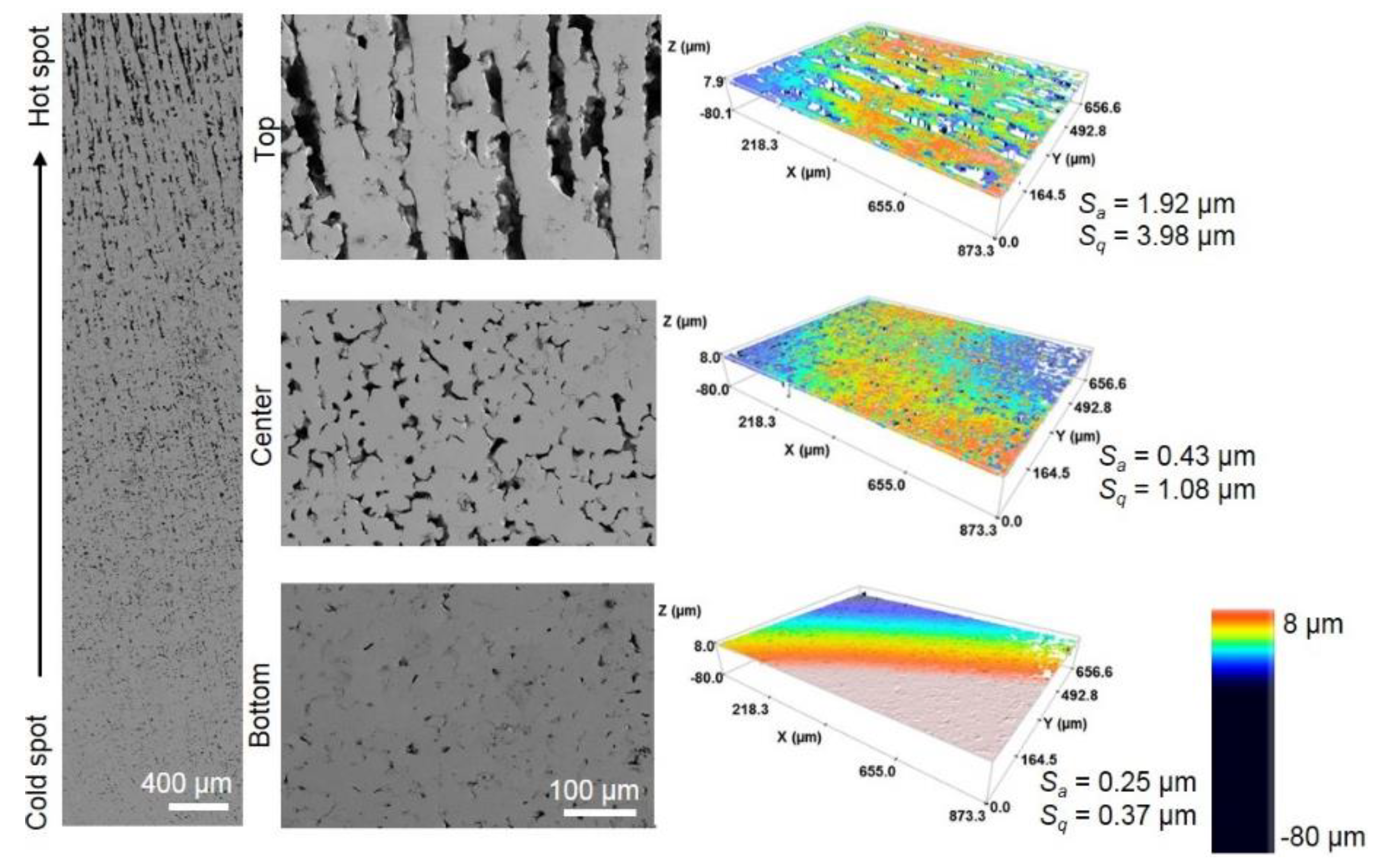
Then, new porous cylinders were fabricated using Teflon® molds, considering the experimental conditions for which better results were obtained using alumina molds and the cryogenic solution as cold spot. Figure 3 shows SEM micrographs of the whole longitudinal section of one sample obtained under these conditions as well as higher magnification images of the main three studied areas: top, center and bottom. It can be clearly observed the porosity gradient, being able to identify the three above mentioned zones: bottom (close to the cold surface), center and top (near the hot surface). Note that porosity is very different in these three areas, in terms of percentage, size and morphology (aspect ratio, defined as the ratio between the maximum diameter vs minimum diameter).
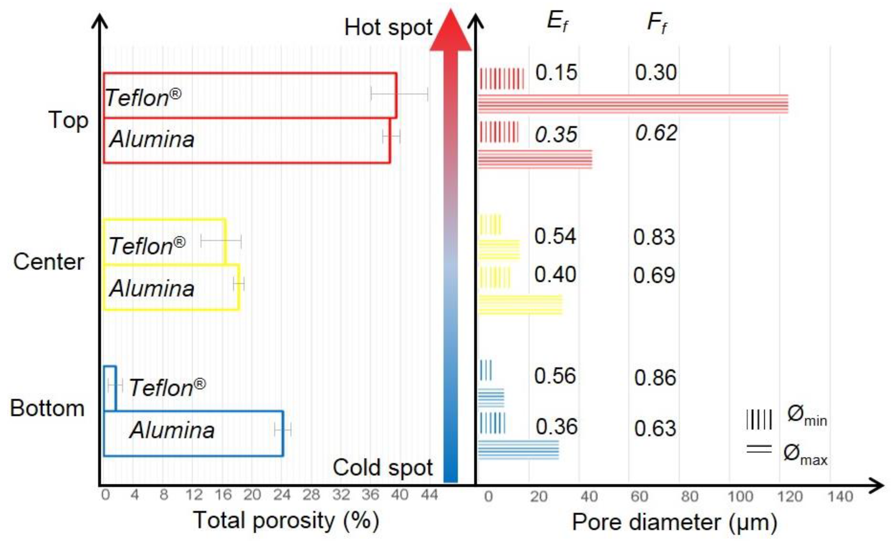
Focusing on the analysis of the porosity and the pores (size and distribution), Figure 4 displays the values of the porosity and the morphology of the pores, maximum and minimum diameter, obtained in the different zones of the cylinder and both type of molds, Teflon® and alumina, used in this work. The graphic represents the porosity for the three area and the two types of molds. In terms of total porosity, it is similar for both materials of the molds, around 38.4% (38.3% and 38.5% for alumina and Teflon®, respectively), however, by zone, a clear gradient is observed for Teflon® molds, while using alumina, although there is a variation from the bottom to the top it is not very remarkable. This figure (Figure 4) also shows the minimum and maximum diameter of the pores for each area and the two type of molds with remarkable differences. For example, in the area near the cold spot (bottom), an orientation of the porosity is not achieved and no significant differences are observed in the morphology of the pores when a Teflon® mold is used. However, using an alumina mold, the mean size of the pores is higher in this area. Besides, in the center of the cylinders manufactured with Teflon® molds, the presence of elongated porosity begins to be observed, although the change is very slight. In addition, the content and size of the pores are larger in top zone for Teflon® compared to alumina molds. Finally, regardless of the type of mold used, more elongated porosity is obtained in the zone near the hot spot for both molds, as it is indicated by the elongation factor (Ef), included in the graphic. It means, the use of more insulating molds decreases the growth rate of the dendrite, favoring the formation of a porosity elongated and oriented in the direction of the thermal gradient. The analyses of the form factor (Ff) also reveals the elongation of the pores in the samples manufacturing with Teflon® while using alumina they are more homogenous, with almost no differences for the three analyzed areas. Therefore, it can be concluded that a better gradient of temperature due to the Teflon® mold can be directly related to the geometry and size of the pores as well as the total porosity.
The cylinders obtained with the Teflon® molds have more suitable pores (interconnected porosity and sizes larger than 100 μm are required) to favor vascularization processes and the growth of bone tissue into the implant. Another important aspect in the biofunctional behavior is the roughness of the walls of the pores, as it can be detailed observed in the SEM micrographs (high magnification) shown in Figure 5. The authors of this work have already reported roughness similar to those shown here for porous c.p. Ti samples manufacturing by conventional powder metallurgy and space-holder technique patterns (staircase-like) and levels (micrometric scale) [32,33,34,35]. In this context, the role of surface roughness inside pores on cell differentiation and osteoblast adhesion has to be discussed. Inside the pores, attached osteoblast cells to the walls notice higher load transfer and this local stress promotes cell differentiation and mineralization and, therefore, the potential implant osseointegration [36]. Then, the study of the surface roughness of implants is critical for biomedical applications, as it is this case. In fact, a study with confocal optical microscopy (color images of Figure 3) has been performed in order to quantify the roughness (indicated in Figure 3). It revealed that the arithmetic mean value of surface roughness, Sa, at the bottom is almost half than the center part (0.25 vs 0.43 μm, respectively) and Sa increases up to five times at the top, corroborating the increase of roughness as the porosity grows (increasing number and size of the pores). Concerning the other parameter related to roughness, root mean square height (Sq), also followed a similar tendency, increasing from the bottom to the top part of the porous c.p. Ti cylinders.

3.2. Fabrication of the Porous Substrates Using a Thermostatic Bath

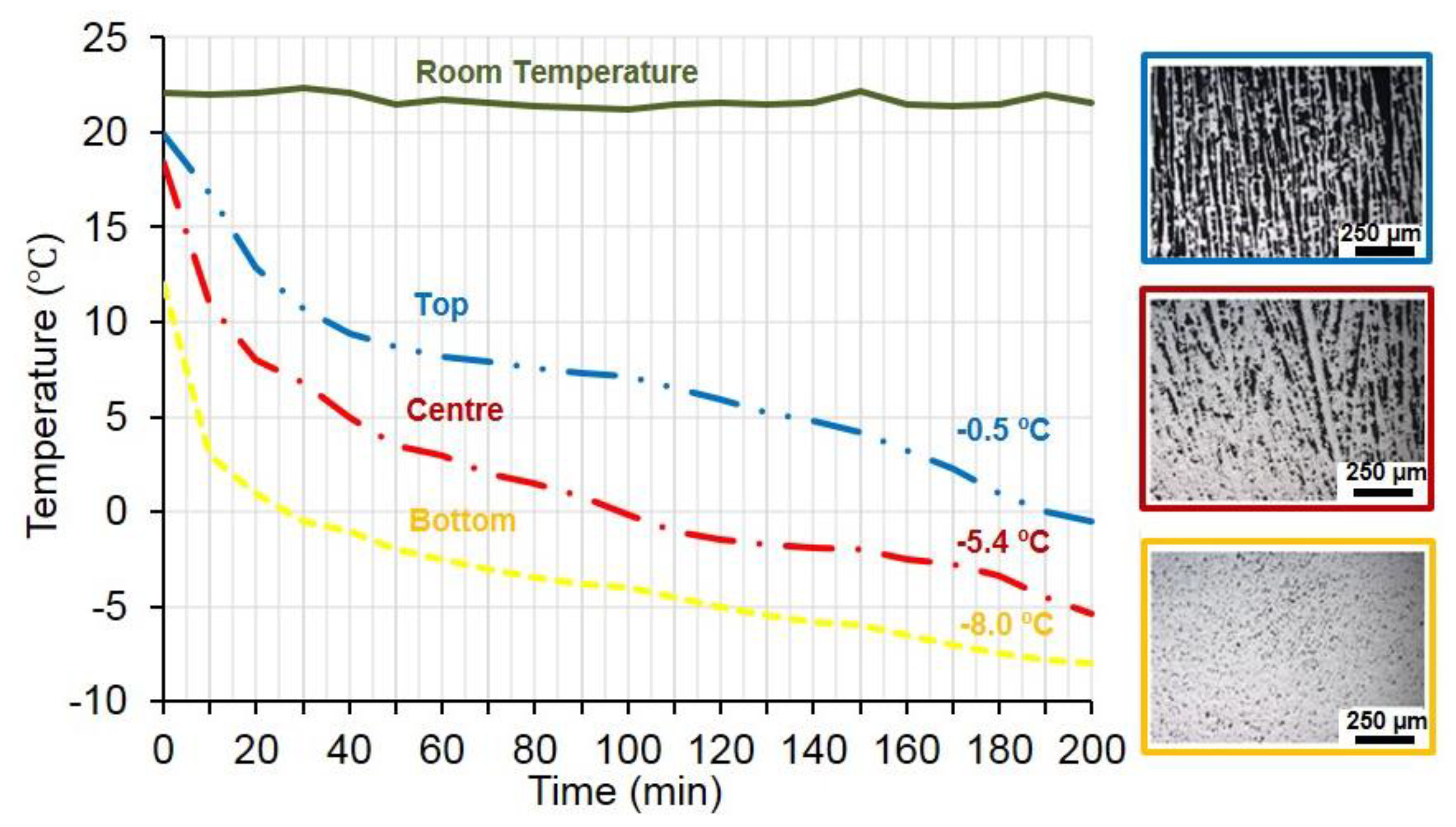
In view of the obtained results, it is clear that there is a clear dependence on the porosity (percentage, geometry and pore size) on the temperature gradient. Therefore, to understand the mechanism responsible for the solidification process, in this work authors tried to establish a correlation among the temperatures that is reached in each of the three main areas of the cylinder, the solidification front speed of the slurry and the obtained distribution of the porosity. For this purpose, samples have been fabricated using a thermostatic bath to generate the cold spot. The evolution of the temperatures registered by thermal sensors are depicted in a graphic (Figure 6), at the three main areas (bottom, center, top) as well as the hot spot, for the whole process, until solidification.
Each area corresponds, approximately, to 5 mm of height (bottom = 5 mm; center = 10 mm; top 15 mm). The cold spot is controlled by the thermostatic bath and it is considered constant. Concerning the temperatures registered by the thermal sensors, the one located at the bottom achieved the set point (−0.5 °C) in 30 min, so it means the time that the solidification front spent to achieve 5 mm height. The next step, at 10 mm from the bottom, −0.5 °C was reached 60 min after the first one and the one of the top needed a total amount of 200 min for the solidification. The registration of the temperature, time and position of the solidification front allowed calculating its growing velocity, observing that at the bottom it is 0.083 mm/min, which was very high and, therefore, Ti particles were entrapped. In the center, the speed was still high but a bit lower, 0.055 mm/min, so not many particles were entrapped and the pores started to form. Once the solidification front achieved the top area, at a height of 15 mm, the velocity decreased up to 0.050 mm/min and elongated pores were formed. Consequently, it could be said that there is a critical growth velocity for the formation of the desirable elongated pores. Such values should be between 0.050 and 0.005 mm/min according to the obtained results. The effect of the velocity has been already reported as a function of the particle sizes [16].

3.3. Mechanical Behavior of Porous Titanium Cylinders

This section discusses the results concerning the mechanical properties of the porous cylinder fabricated under the experimental conditions, it means, ΔT = 32 °C for a Teflon® mold of inner diameter 12 mm. Firstly, this study includes the experimentally values obtained by ultrasound (dynamic Young’s modulus, Ed) and uniaxial compression tests (yield strength, σy, and Young’s modulus, Ec) for the whole sample. Then, these mechanical properties have been estimated for each area of interest (bottom, center and top) by theoretical models and/or equations which relates microstructural variables and mechanical behavior. Finally, calculated and estimated values are discussed in terms of the porosity of each areas as well as the mechanical requirements of the samples, taking in account its potential application as dental implant.
Table 1 summarizes all the results, experimental and estimated, including those referring to the porosity measured by Archimedes’ and IA, since they have been used in the equations to estimate the mechanical properties.
The experimental measure of the stiffness of porous materials is not trivial and has aroused controversy among the scientific community. Considering the advantages and disadvantages of the experimental techniques to evaluate the Young’s modulus of porous material, in this work, it has been evaluated following the two methods above mentioned (uniaxial compression test and ultrasounds technique), obtaining a higher value by ultrasounds than compression test (35 GPa vs 19 GPa, respectively). It has been previously reported by some of authors of this work [33,34,37,38] that there is a discrepancy between the value obtained by applying both experimental techniques. In Ni-Ti materials, this difference in the measured values is related to a super-elastic deformation within the linear-elastic range; it has been observed that, by the ultrasound technique, stiffness decreases for higher porosity values, according to the elastic Eshelby-based theory for closed, spherical porosity [39]. Besides, Torres et al. [33] described a similar behavior for other porous materials, associating it to a stiffness testing machine effect, since the mechanical system and the sample were considered as two springs in series. Furthermore, it is worth remembering that the cross-section of a c.p. Ti cylinder is not completely homogenous and the material begins to collapse at the lowest c.p. Ti content. Though, Young´s modulus estimation by ultrasounds depends on the wave velocity through the whole sample. Then, modifications on one of the experimental parameters (time of transfer, attenuation, reflection and frequency) could be already related to changes on the physical properties’ (Young’s modulus, density). Focusing on the results obtained in this work, those measured by ultrasounds can be accepted since they can be validated to the estimated values according to Nielsen equation [30], which also considers experimental porosity data.
Considering the gradient of porosity, the results should be analyzed for each main area of the cylinder (top, center, bottom), so the Young´s modulus and yield strength has been estimated as a function percentage of porosity and morphology of the pores of the (Table 1). As it could be expected, Young’s modulus diminishes for higher porosity. But it has been observed that even when total porosity in the main parameter affecting the mechanical properties, other variables are also important, such as those related to the morphology of the pores. A priori, it would be expected a total yield strength similar to the one measured at the top, since it was the lower value. However, the experimental measures reveal higher values (396 vs 312 MPa, respectively) which could be associated to the orientation of the pores respect to the uniaxial mechanical applied stress. It means, that Equation (3) only considers Pi while the compression test also considers the size and morphology of the pores. Then, in the area with elongated and oriented pores, the minimum diameter of the pore influences the results since it is perpendicular to the applied effort and, for this reason, the effort is greater than the estimated. Also, it is very noticeable their effects on the yield strength, due to the increasing Ti matrix as well as the increase on the Ff, in other words, to a better quality of the sintering necks. Here, pores produces notch-strengthening, reducing the strength effective area. According to it, interconnected porosity induces a triaxial effect which could compensate the low strength associated to highly-porous materials.
Although an elongated porosity has not been achieved throughout the entire cylinder under the experimental conditions used, we note that the porosity gradient from the top to the bottom could be suitable for some applications in the biomedical sector (for instance, dental implants, lumbar interbody fusion). With the results, it can be considered that, on the one hand, the top of the sample (hot spot) could be in contact with a cortical bone, since it presents stiffness and yield strength values suitable to solve both the stress-shielding and to guarantee the mechanical properties of the cortical bone (E = 20‒25 GPa; σy = 150‒180 MPa). On the other hand, the less porous cylinder area (near to cold spot) could be in contact with prosthetic crown in oral implantology, since in this area we would need a stiffer biomaterial with better mechanical performance (fracture and fatigue resistance).
The obtained porosity has been related to the biomechanical and biofunctional behavior of the cylinders. However, Equations (1)‒(3) also allow one to estimate the characteristics of the required porosity to obtain desired mechanical properties (stress’ distribution and/or cellular necessities of the bone tissue) of the implant. It could be useful to be applied with innovative manufacturing techniques, which are more expensive (for instance, laser sintering, spark plasma sintering, electron beam melting or selective laser melting, electric current activated/assisted sintering). By freeze-casting, it is possible to economically fabricate controlled porous samples by the optimization of the experimental parameters during fabrication (i.e., gradient of temperature, size and material of the mold).

4. Conclusions

The obtained results can be summarized as a detailed study of the influence of all the experimental conditions of manufacturing by freeze-casting: gradient of temperature, material and size of the mold on the resulting microstructure and mechanical properties of porous c.p. Ti cylinders for bone replacement.
The optimization of the more suitable processing conditions which are based on the fact that they results in: 1) a larger area with elongated and oriented porosity, very similar to the desirable values, and 2) sizes and level of interconnectivity that allow bone ingrowth into the implant. These results have been obtained using Teflon® molds of 12 mm of inner diameter and ΔT = 32 °C. In addition, it is worth to highlight the roughness of the pore walls, and their potential involvement in the improvement of the osseointegration of the pieces manufactured by freeze-casting technique.
The cylinders have a gradient porosity suitable for use in dentistry, presenting higher Young´s modulus and yield strength at the bottom (Ed = 106 GPa and σy = 644 MPa), near the cold spot and, therefore better mechanical resistance (it would be in contact with a prosthetic crown), while the opposite side, the hot spot, has bigger, elongated pores and walls (Ed =20.9 GPa, σy = 312 MPa, and a pore size of 123 μm). Gradual needs of each zone to meet the different stiffness and resistance requirements of the application can be achieved by this fabrication technology.
In summary, freeze-casting technique is a suitable and economical procedure for manufacturing porous c.p. Ti cylinders for bone replacements, achieving the biomechanical and biofunctional balance, required for an improved and successful osseointegration.

Author Contributions

Conceptualization, project administration, supervision J.A.R.-O., D.C.D. and Y.T.; investigation, formal analysis, validation P.T., A.M.B., J.M.B., D.F.L. and E.A.; discussion and writing—original draft preparation, all the authors. All authors have read and agreed to the published version of the manuscript.

Funding

This research was funded by Ministry of Economy and Competitiveness of Spain under the grant MAT2015-71284-P and the regional government from Andalusia through FEDER-Junta de Andalucía Research Project (Modeling and implementation of the freeze casting technique: gradients of porosity with a tribo-mechanical equilibrium and electro-stimulated cellular behavior).

Acknowledgments

Authors thank to undergraduate students for their contribution to the experimental work (Joaquin R. Bascón, David Daza, Pablo Gomez and Miguel Roldan).

Conflicts of Interest

The authors declare no conflict of interest.

References

  1. USA Arthritis Prevention, Treatment, and Rehabilitation. Hearing before the Subcommittee on Public Health and Environment of the Committee on Interstate and Foreign Commerce House of Representative; U.S. Government Printing Office Washington: Washington, DC, USA, 1975; pp. 93–102.
  2. Norowski, P.A.; Bumgardner, J.D. Biomaterial and antibiotic strategies for peri-implantitis. J. Biomed. Mater. Res. Part B Appl. Biomater. 2009, 88, 530–543. [Google Scholar] [CrossRef]
  3. Ning, C.; Zhou, L.; Tan, G. Fourth-generation biomedical materials. Mater. Today 2016, 19, 2–3. [Google Scholar] [CrossRef]
  4. Khorasani, A.M.; Goldberg, M.; Doeven, E.H.; Littlefair, G. Titanium in Biomedical Applications-Properties and Fabrication: A Review. J. Biomater. Tissue Eng. 2015, 5, 593–619. [Google Scholar] [CrossRef]
  5. Tengvall, P.; Elwing, H.; Sjöqvist, L.; Lundström, I.; Bjursten, L.M. Interaction between hydrogen peroxide and titanium: A possible role in the biocompatibility of titanium. Biomaterials 1989, 10, 118–120. [Google Scholar] [CrossRef]
  6. Kaur, M.; Singh, K. Review on titanium and titanium based alloys as biomaterials for orthopaedic applications. Mater. Sci. Eng. C 2019, 102, 844–862. [Google Scholar] [CrossRef]
  7. Rho, J.Y.; Ashman, R.B.; Turner, C.H. Young’s modulus of trabecular and cortical bone material: Ultrasonic and microtensile measurements. J. Biomech. 1993, 26, 111–119. [Google Scholar] [CrossRef]
  8. Karageorgiou, V.; Kaplan, D. Porosity of 3D biomaterial scaffolds and osteogenesis. Biomaterials 2005, 26, 5474–5491. [Google Scholar] [CrossRef]
  9. Murphy, C.M.; O’Brien, F.J. Understanding the effect of mean pore size on cell activity in collagen-glycosaminoglycan scaffolds. Cell Adhes. Migr. 2010, 4, 377–381. [Google Scholar] [CrossRef] [Green Version]
  10. Jamshidinia, M.; Wang, L.; Tong, W.; Ajlouni, R.; Kovacevic, R. Fatigue properties of a dental implant produced by electron beam melting ® (EBM). J. Mater. Process. Technol. 2015, 226, 255–263. [Google Scholar] [CrossRef]
  11. Amin Yavari, S.; Ahmadi, S.M.; Wauthle, R.; Pouran, B.; Schrooten, J.; Weinans, H.; Zadpoor, A.A. Relationship between unit cell type and porosity and the fatigue behavior of selective laser melted meta-biomaterials. J. Mech. Behav. Biomed. Mater. 2015, 43, 91–100. [Google Scholar] [CrossRef]
  12. Zhao, D.; Huang, Y.; Ao, Y.; Han, C.; Wang, Q.; Li, Y.; Liu, J.; Wei, Q.; Zhang, Z. Effect of pore geometry on the fatigue properties and cell affinity of porous titanium scaffolds fabricated by selective laser melting. J. Mech. Behav. Biomed. Mater. 2018, 88, 478–487. [Google Scholar] [CrossRef] [PubMed]
  13. Zhao, S.; Li, S.J.; Wang, S.G.; Hou, W.T.; Li, Y.; Zhang, L.C.; Hao, Y.L.; Yang, R.; Misra, R.D.K.; Murr, L.E. Compressive and fatigue behavior of functionally graded Ti-6Al-4V meshes fabricated by electron beam melting. Acta Mater. 2018, 150, 1–15. [Google Scholar] [CrossRef]
  14. Ren, D.; Li, S.; Wang, H.; Hou, W.; Hao, Y.; Jin, W.; Yang, R.; Misra, R.D.K.; Murr, L.E. Fatigue behavior of Ti-6Al-4V cellular structures fabricated by additive manufacturing technique. J. Mater. Sci. Technol. 2019, 35, 285–294. [Google Scholar] [CrossRef]
  15. Trueba, P. Desarrollo de titanio con porosidad gradiente radial y longitudinal para aplicaciones biomédicas. Ph.D Thesis, University of Seville, Sevilla, Spain, 2017. [Google Scholar]
  16. Chino, Y.; Dunand, D.C. Directionally freeze-cast titanium foam with aligned, elongated pores. Acta Mater. 2008, 56, 105–113. [Google Scholar] [CrossRef]
  17. Maxwell, W.A.; Gurnick, R.S.; Francisco, A.C. Preliminary investigation of the freeze-casting method for forming refractory powders. Natl. Advis. Comm. Aeronaut. 1954, RME53L21, 20. [Google Scholar]
  18. Tong, H.M.; Gryte, C.C. Mechanism of lamellar spacing adjustment in directionally frozen agar gels. Colloid Polym. Sci. 1985, 263, 147–155. [Google Scholar]
  19. Tong, H.M.; Noda, I.; Gryte, C.C. No CPS 768 Formation of anisotropic ice-agar composites by directional freezing. Colloid Polym. Sci. 1984, 262, 589–595. [Google Scholar] [CrossRef]
  20. Schoof, H.; Apel, J.; Heschel, I.; Rau, G. Control of pore structure and size in freeze-dried collagen sponges. J. Biomed. Mater. Res. 2001, 58, 352–357. [Google Scholar] [CrossRef]
  21. Deville, S. Freeze-casting of porous biomaterials: Structure, properties and opportunities. Materials 2010, 3, 1913–1927. [Google Scholar] [CrossRef]
  22. Deville, S. Freeze-casting of porous ceramics: A review of current achievements and issues. Adv. Eng. Mater. 2008, 10, 155–169. [Google Scholar] [CrossRef]
  23. Liu, R.; Xu, T.; Wang, C. A review of fabrication strategies and applications of porous ceramics prepared by freeze-casting method. Ceram. Int. 2016, 42, 2907–2925. [Google Scholar] [CrossRef]
  24. Li, J.C.; Dunand, D.C. Mechanical properties of directionally freeze-cast titanium foams. Acta Mater. 2011, 59, 146–158. [Google Scholar] [CrossRef]
  25. Scotti, K.L.; Dunand, D.C. Freeze casting—A review of processing, microstructure and properties via the open data repository, FreezeCasting. net. Prog. Mater. Sci. 2018, 94, 243–305. [Google Scholar] [CrossRef] [Green Version]
  26. Muñoz, P.T.; Bascón Suá, J.R.; Beltrán, A.M.; Rodriguez-Ortiz, J.A.; Hernández, Y.T.; Palacio, J.J.P.; Álvarez, E.A.; Dunand, D.C. A simple and economical device to process Ti cylinders with elongated porosity by freeze-casting techniques: Design and manufacturing. Key Eng. Mater. 2018, 770, 255–261. [Google Scholar]
  27. Lascano, S.; Arévalo, C.; Montealegre-Melendez, I.; Muñoz, S.; Rodriguez-Ortiz, J.A.; Trueba, P.; Torres, Y. Porous titanium for biomedical applications: Evaluation of the conventional powder metallurgy frontier and space-holder technique. Appl. Sci. 2019, 9, 982. [Google Scholar] [CrossRef] [Green Version]
  28. Li, Y.; Yang, C.; Zhao, H.; Qu, S.; Li, X.; Li, Y. New developments of ti-based alloys for biomedical applications. Materials 2014, 7, 1709–1800. [Google Scholar] [CrossRef] [Green Version]
  29. Shen, H.; Brinson, L.C. Finite element modeling of porous titanium. Int. J. Solids Struct. 2007, 44, 320–335. [Google Scholar] [CrossRef] [Green Version]
  30. Nielsen, L.F. On strength of porous material: Simple systems and densified systems. Mater. Struct. Constr. 1996, 31, 651–661. [Google Scholar] [CrossRef]
  31. Imwinkelried, T. Mechanical properties of open-pore titanium foam. J. Biomed. Mater. Res. Part A 2007, 81, 964–970. [Google Scholar] [CrossRef]
  32. Wen, C.E.; Yamada, Y.; Shimojima, K.; Chino, Y.; Asahina, T.; Mabuchi, M. Processing and mechanical properties of autogenous titanium implants materials. J. Mater. Sci. Mater. Med. 2002, 13, 397–401. [Google Scholar] [CrossRef]
  33. Torres, Y.; Rodríguez, J.A.; Arias, S.; Echeverry, M.; Robledo, S.; Amigo, V.; Pavón, J.J. Processing, characterization and biological testing of porous titanium obtained by space-holder technique. J. Mater. Sci. 2012, 47, 6565–6576. [Google Scholar] [CrossRef]
  34. Muñoz, S.; Pavón, J.; Rodríguez-Ortiz, J.A.; Civantos, A.; Allain, J.P.; Torres, Y. On the influence of space holder in the development of porous titanium implants: Mechanical, computational and biological evaluation. Mater. Charact. 2015, 108, 68–78. [Google Scholar] [CrossRef]
  35. Domínguez-Trujillo, C.; Beltrán, A.M.; Garvi, M.D.; Salazar-Moya, A.; Lebrato, J.; Hickey, D.J.; Rodríguez-Ortiz, J.A.; Kamm, P.H.; Lebrato, C.; García-Moreno, F.; et al. Bacterial behavior on coated porous titanium substrates for biomedical applications. Surf. Coatings Technol. 2019, 357, 896–902. [Google Scholar] [CrossRef]
  36. Civantos, A.; Domínguez, C.; Pino, R.J.; Setti, G.; Pavón, J.J.; Martínez-Campos, E.; Garcia Garcia, F.J.; Rodríguez, J.A.; Allain, J.P.; Torres, Y. Designing bioactive porous titanium interfaces to balance mechanical properties and in vitro cells behavior towards increased osseointegration. Surf. Coatings Technol. 2019, 368, 162–174. [Google Scholar] [CrossRef]
  37. Torres, Y.; Pavón, J.J.; Nieto, I.; Rodríguez, J.A. Conventional powder metallurgy process and characterization of porous titanium for biomedical applications. Metall. Mater. Trans. B Process Metall. Mater. Process. Sci. 2011, 42, 891–900. [Google Scholar] [CrossRef]
  38. Castillo, S.M.; Muñoz, S.; Trueba, P.; Eduardo, D.; Torres, Y. Influence of the Compaction Pressure and Sintering temperature on the mechanical properties of porous titanium for biomedical applications. Metals 2019, 9, 1249. [Google Scholar] [CrossRef] [Green Version]
  39. Greiner, C.; Oppenheimer, S.M.; Dunand, D.C. High strength, low stiffness, porous NiTi with superelastic properties. Acta Biomater. 2005, 1, 705–716. [Google Scholar] [CrossRef]
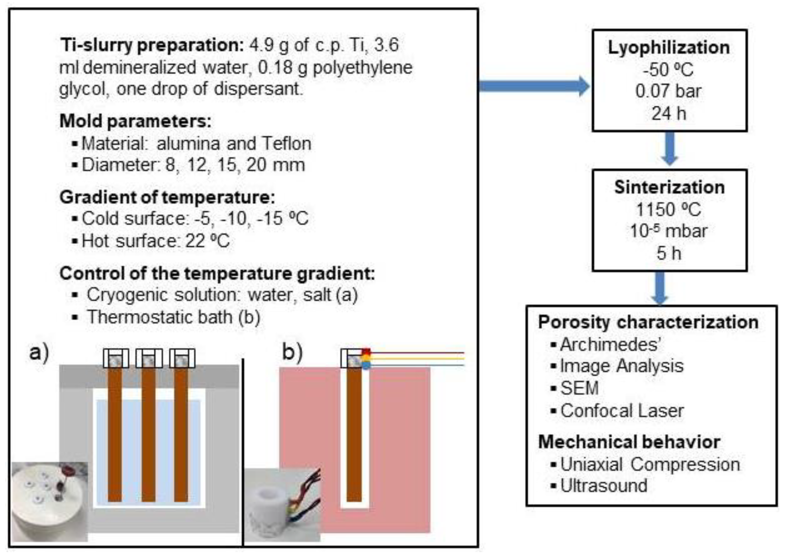
Figure 1. Flow diagram of the manufacturing and characterization of controlled porosity on c.p. Ti cylinders fabricated by freeze-casting and scheme of the device of (a) home-made device with the cryogenic solution and (b) the thermostatic bath. Inset: photo of both systems.
Metals 10 00188 g001
Figure 2. SEM micrographs of the top zones of porous c.p. Ti substrates fabricated by freeze-casting with alumina mold of different diameters and temperature of the cold spot using the cryogenic solution as cold spot. Scale bar: 500 μm.
Metals 10 00188 g002
Figure 3. SEM micrographs of the longitudinal section of a porous c.p. Ti cylinder and details of the main areas (bottom, center, top). Confocal optical image of the surfaces for this area (in color), with common scale bar. Inserted: main roughness parameters.
Metals 10 00188 g003
Figure 4. Influence of the material of the molds in the total porosity and pore diameter for c.p. Ti cylinders fabricated with Teflon® and alumina molds, under the same experimental conditions, for the three main areas of the cylinders: top, center and bottom. Also, the elongation and shape factor are included for each material of the mold and area of interest. Standard deviation for the maximum and minimum diameters is <1.
Metals 10 00188 g004
Figure 5. SEM micrographs of a pore of the top area of the porous c.p. Ti cylinder fabricated by freeze-casting.
Metals 10 00188 g005
Figure 6. Variation of the registered temperatures at the bottom, center, top and room temperature (hot spot) during the fabrication of c.p. Ti cylinders with a Teflon® mold using a thermostatic bath as cold spot.
Metals 10 00188 g006
Table 1. Experimental parameters obtained by Archimedes’ (Pi, PT), IA (PT, Ff), ultrasound technique (Ed) and uniaxial compression test (σy, Ec) to fabricate porous graded cylinders of c.p. Ti by freeze-casting (ΔT = 32 °C for a Teflon® mold of inner diameter 12 mm). Estimated dynamic Young’s modulus, Ed, (GPa) and estimated yield stregth, σy (MPa) for each area of interest.
Area of the Sample Pi (%)PT (%)FfUltrasound TechniqueUniaxial Compression Test
Archimedes’IATestEstimated Dynamic Young’s Modulus, Ed, (GPa)Testσy (MPa) Estimated by Equation (3)
Equation (1)Equation (2)Ec (GPa)σy (MPa)
Top18.338.539.50.3035.346.520.8619396312
Center16.40.8375.974.36514
Bottom1.70.86103.0105.97644