Article

Sustainability Assessment, Investigations, and Modelling of Slot Milling Characteristics in Eco-Benign Machining of Hardened Steel

by
Angelos P. Markopoulos
1,
Nikolaos E. Karkalos
1,
Mozammel Mia
2,*,
Danil Yurievich Pimenov
3,
Munish Kumar Gupta
3,4,
Hussein Hegab
5,
Navneet Khanna
6,
Vincent Aizebeoje Balogun
7 and
Shubham Sharma
8
1
School of Mechanical Engineering, National Technical University of Athens, Heroon Polytechniou 9, 15780 Athens, Greece
2
Department of Mechanical Engineering, Imperial College London, London SW7 2AZ, UK
3
Department of Automated Mechanical Engineering, South Ural State University, Lenin Prosp. 76, 454080 Chelyabinsk, Russia
4
Key Laboratory of High Efficiency and Clean Mechanical Manufacture, Ministry of Education, School of Mechanical Engineering, Shandong University, Jinan 250061, China
5
Mechanical Design and Production Engineering Department, Cairo University, Giza 12163, Egypt
6
Advanced Manufacturing Laboratory, Institute of Infrastructure Technology, Research and Management, Ahmedabad 380008, India
7
Department of Mechanical Engineering, Faculty of Engineering, Edo University Iyamho, Edo State 312101, Nigeria
8
Department of Mechanical Engineering, IKG Punjab Technical University, Jalandhar-Kapurthala Road, Kapurthala 144603, India
*
Author to whom correspondence should be addressed.
Metals 2020, 10(12), 1650; https://doi.org/10.3390/met10121650
Submission received: 31 October 2020 / Revised: 30 November 2020 / Accepted: 1 December 2020 / Published: 7 December 2020
(This article belongs to the Special Issue Optimization and Analysis of Metal Cutting Processes)

Abstract

:
The hardened tool steel AISI O1 has increased strength, hardness, and wear resistance, which affects the complexity of the machining process. AISI O1 has also been classified as difficult to cut material hence optimum cutting parameters are required for the sustainable machining of the alloy. In this work, the effect of feed peer tooth (fz), cutting speed (vc), cutting of depth (ap) on surface roughness (Ra, Rt), cutting force (Fx, Fy), cutting power (Pc), machining cost (Ci), and carbon dioxide (Ene) were investigated during the slot milling process of AISI O1 hardened steel. A regression analysis was carried out on the obtained experimental results and the induction of nonlinear mathematical equations of surface roughness, cutting force, cutting power, and machining cost with a high coefficient of determination (R2 = 90.62–98.74%) were deduced. A sustainability assessment model is obtained for optimal and stable levels of design variables when slot milling AISI O1 tool steel. Stable indicators to ensure personal health and safety of operation, P1 values were set to “1” at a cutting speed of 20 m/min or 43.3 m/min and “2” at a cutting speed of 66.7 m/min or 90 m/min. It is revealed that for eco-benign machining of AISI O1, the optimum parameters of 0.01 mm/tooth, 20 m/min, and 0.1 mm should be adopted for feed rate, cutting speed, and depth of cut respectively.

1. Introduction

Hardened steel AISI O1 is widely used in the manufacturing of measuring and cutting tools, cold forming matrix and punches, and machine-tool attachments. The presence of manganese, vanadium, tungsten, chromium, and carbides in its composition contributes to the increase in strength [1,2], hardness [3], and wear resistance [4]. Due to these properties, AISI O1 steel products are employed in different industries and its machinability has been investigated in different operations: turning [5], milling [6], and grinding [7]. In the process of slot milling, the main indicator of the quality of the machined surface is the roughness. However, the environmental aspect of the machining process is of increasing importance today [8,9]. Production should not only provide accurate processing parameters but also use more productive methods and technologies [9] to fulfil the dream of a sustainable society [10].
Today, sustainable manufacturing is relevant, which focused on ensuring the quality of machined surfaces with lower costs of production resources [11], thereby reducing their overall consumption and reducing the negative impact on the environment [12]. Besides, a very important aspect is to reduce greenhouse gases to achieve reliable and sustainable manufacturing processes [13]. Thus, it is important to comprehensively ensure optimal conditions of machining to achieve the target accuracy in any machining operation [14], optimal from the standpoint of saving resources [15], cutting conditions [16], and ensuring less environmental impact [17].
Only a few studies focused on the optimisation of machining process parameters to achieve less environmental impact and improve the surface integrity and quality aspects for slot milling operations. Wang and Chang [18] in their article showed the relationship between the cutting parameters and the geometry of the cutter on the induced surface roughness when the slot end milling of aluminium alloy 2014-T6. Niknam and Songmene [19] in their study minimised burr thickness and surface roughness during slot milling of aluminium alloy 6061-T6. Pimenov in his work [20] investigated the influence of cutting conditions on the surface roughness obtained by milling a billet of steel 45. Duboust et al. [21] showed a change in surface quality when using different types of cutting tools, fibre orientation, and cutting settings for milling operations. Niknam et al. [22] determined the optimal levels of adjustment of the milling parameters by improving the surface quality in the process of slot milling of aluminium alloys 2024-T351 and 6061-T6. However, based on the information available in the open access literature, especially for slot milling operations, it can be observed that the published work did not consider the processing of hardened steel. Besides, no consideration is provided to the environmental aspects and the costs of production resources.
In considering the research on the surface quality during slot milling in combination with other parameters, such as cutting force, Wang et al. [23] investigated the influence of the fibre cutting angle on milling forces, morphology of machined surface, and surface roughness when slot milling unidirectional high strength polymer laminates reinforced with carbon fibre. Pimenov et al. [24] demonstrated the effect of relative positions of face mill concerning the workpiece and kinematics milling on component cutting forces, acceleration spindle during milling, and on the surface quality obtained by milling SAE 1045 steel. Jebaraj et al. [25] investigated the surface roughness taking into account cutting forces when milling of aluminium alloy 6082-T6. Yeganefar et al. [26] made a forecast and optimisation of surface quality and cutting forces during slot milling of the aluminium alloy 7075-T6. Pimenov et al. [27] in their article for the face milling process of AISI 1045 steel, surface roughness, cost of the cutting tool, power consumption, wear, and material removal rate were studied. Balogun et al. [28] investigated tool life characteristics, tool wear parameters, surface integrity, cutting forces, and power demand when turning Nitronic 33 steel alloy under different cutting environment. Osman et al. [29] studied the effect of a minimal amount of lubricant with various combinations of hexagonal boron nitride nanoparticles on surface quality, and the cutting force of slotted milling titanium alloy using analysis of variance and response surface methodology. Considering the reviewed literature on surface quality and cutting forces obtained by slot milling, the presented work do not consider the processing and the environmental aspect during slot milling of hardened steel AISI O1.
A very interesting factor in addition to ensuring the surface quality of processed slot milling is to minimise the cutting power. Among such works, one can single out studies [30] of surface quality and analysis of energy consumption of austenitic stainless steel, crushed in a dry cutting milled. Liu et al.’s [31] model was used to determine the cutting force and power at the tool tip. This was obtained analytically for slot milling operations. Liu et al. [32] presented a new model for predicting surface quality with slot milling of aluminium alloy 7075, taking into account the analytical evaluation of the specific power consumption of cutting and the empirical characteristic of the relationship between surface quality and specific cutting energy consumption. Edem and Balogun [33] investigated the influence of cutting edge radius on the specific cutting energy and surface finish during the side milling of aluminium alloy AW6082-T6 and AISI 1018 steel under a dry cutting environment. Pimenov et al. [34] predicted deviations of surface roughness in real-time using the artificial intelligence, which depends on the power of the main drive and tool wear during milling of steel 45. Additionally, these works dedicated to slot milling concerning cutting power do not consider the machining of hardened steel AISI O1. Besides, they do not take into account the eco-aspect of production, combined with the minimisation of the number of productive resources. Additionally, at the same time, the stability assessment of the material was not reported.
The cost of production is a very important indicator of financial resource savings. Hence, for eco-benign machining of hardened steel, it is important to include the cost component for sustainable machining [35,36,37].
Thus, flowing from literature, it is appropriate at this time of machining science development for eco-benign manufacturing practices to conduct comprehensive studies on the sustainability assessment of slot milling of hardened steel AISI O1. This will take into account the parameter variability for quality of the machined surfaces, cost component resource, and machining process parameters (i.e., cutting force, cutting power, etc.) and most importantly, the conservation of ecology carbon oxide factor.
The purpose of this work is to conduct a sustainability assessment, investigation, and modelling of surface roughness, cutting force, cutting power, machining cost, carbon dioxide emission of slot milling to determine the optimum cutting conditions for cutting power, machining cost, and carbon dioxide emission.

2. Materials and Methods
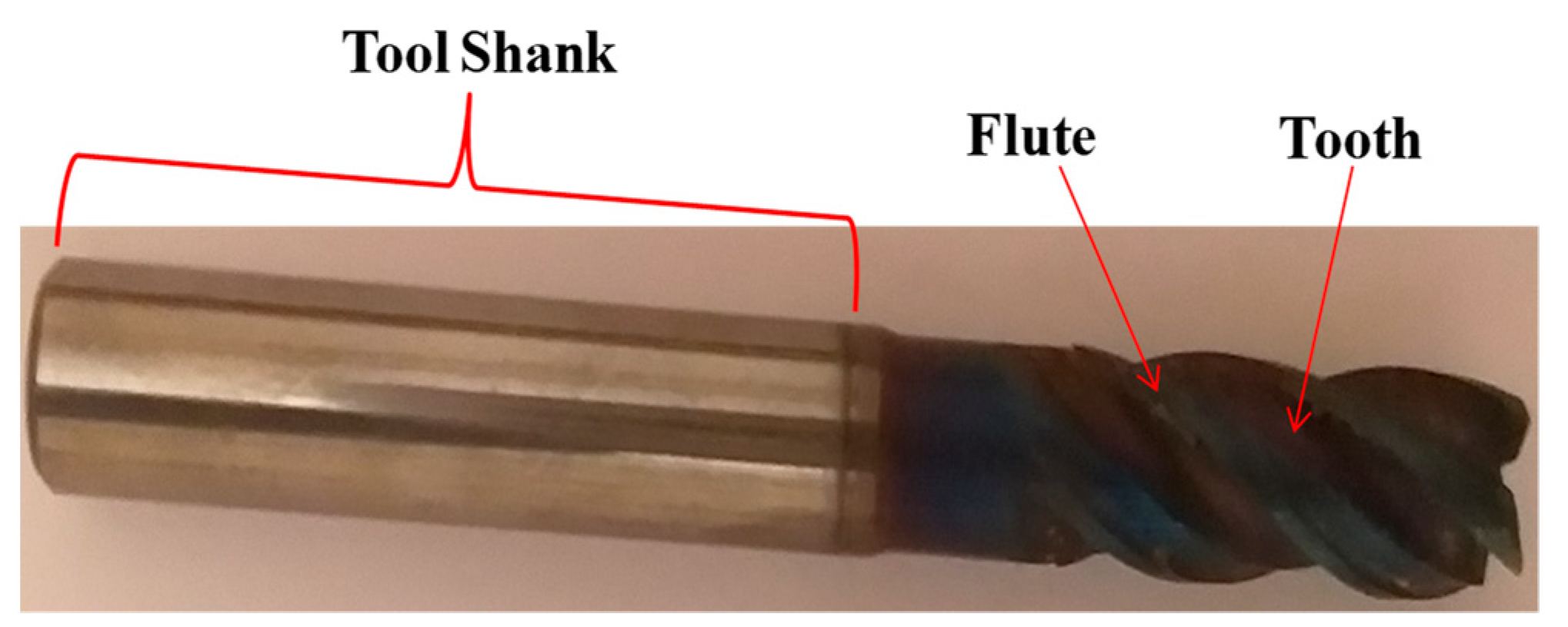
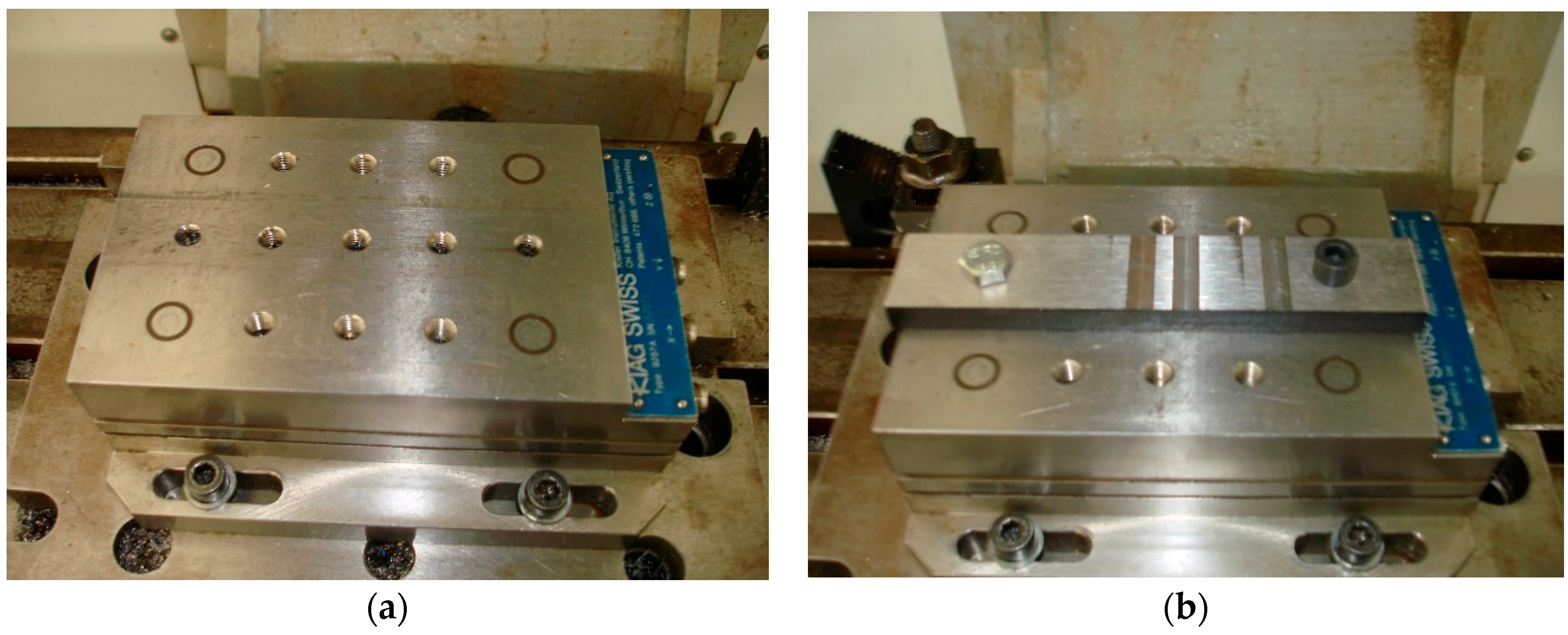
2.1. Experimental

Face milling experimental tests were carried out on a HAAS TM1 vertical machining centre (HAAS, Oxnard, CA, USA). The workpiece material for all experiments was AISI O1 steel, which is oil-hardened cold work tool steel, commonly used for gauges and various types of tools. As per the manufacturer (Uddeholm, Hagfors, Sweeden), the percentage chemical composition of AISI O1 steel is summarised in Table 1.
In order to carry out the machining experiments, two rectangular-shaped workpieces from AISI O1 steel were employed, with dimensions of 150 mm × 30 mm × 10 mm, a hardness value of HB230. For all the milling tests an 8 mm diameter AlTiN coated 4-flute milling cutter was employed as shown in Figure 1. On the workpiece with a cutting length of 30 mm, 8 mm wide slots were machined.
The machine tool employed for the milling tests was a HAAS TM1 3-axis vertical milling centre. The milling tests were designed employing the Taguchi DOE method for three factors, namely depth of cut, cutting speed, and feed rate; for each of these factors, 4 levels were considered. The values of each level for every factor are presented in Table 2 and the sequence of experimental runs was composed of 16 experiments in total.
During the experiments, the three components of cutting force were measured by a Kirstler Type 9257A three-axis dynamometer (triaxial force transducer; Kistler Group, Winterthur, Switzerland), shown in Figure 2a, which was fixed firmly on the machining bed of the milling centre. The workpieces were fixed on it by using two bolts, see Figure 2b.
The measured signal was amplified using three Kirstler Type 5011 charge amplifiers and the force signals were recorded in the PC by using a National Instruments DAQ card. Finally, the acquired force values were processed using specially prepared software in LabView environment and the maximum values for the horizontal force component, Fx, and the vertical force components, Fy were determined in each case.
For the measurement of surface roughness indicators Ra and Rt, a Taylor Hobson Surtronic 3+ profilometer (Taylor Hobson Ltd., Leicester, UK) was employed with a cut-off length value of Lc = 0.8 mm and an evaluation length of Ln = 4.0 mm. Measurements were conducted on three positions along with the slots and average values were calculated.
In order to conduct experiments under various machining conditions without increased experimental work and cost, the experiments of the present work were designed according to the Taguchi Design of Experiments (DoE) method for three factors, namely depth of cut, feed per tooth, and cutting speed, with each factor varying at four different levels. Using Minitab 17 DoE software, the number and the sequence of experimental tests were obtained. In total, 16 experiments were conducted using the L16 orthogonal array, as can be seen in Table 3. In every experiment, uncertainties can arise, e.g., due to the measurement errors or due to factors affecting the process such as mechanical vibrations. To ensure that uncertainties of the slot milling process (in terms of cutting forces and surface roughness measurements) do not affect the results of the present study significantly, several preliminary machining tests were performed with the same parameters as some of the 16 experiments presented in this work. The results indicated that the deviation of average cutting force and surface roughness values does not change considerably during multiple replications of the machining tests and thus, it is not required to perform multiple replications for each of the 16 machining tests. The results of these preliminary tests along with the average values of measured quantities and the coefficient of variation (CV) in each case are presented in Table 4 and Table 5 for cutting force components and surface roughness indicators, respectively. The preliminary tests, which were conducted were performed according to 4 of the 16 conditions included in the manuscript, namely the experiments no. 1, 5, 8, and 13 as presented in Table 3, they were repeated three times each and afterwards, the average Fx and Fy forces, and Ra and Rt were calculated for each replication. The conditions for the preliminary tests were chosen in such a way that they could take into consideration a wide range of the values of each process parameter. The findings indicated that the variation in each case was within acceptable levels, namely below 10% and in most cases even below 5%. Although all three components of cutting force were measured, Fz was neglected from further processing as it is applied perpendicularly to the plane, where cutting action was performed and thus it produced no work.

2.1.1. Cutting Power

Regarding cutting power, the results of force measurements were at first used to calculate the principal cutting force Fc and then cutting power values for each experiment were calculated using Equation (1):
P c = F c v c 6120
where the cutting forces unit is daN (1 daN = 10 N), vc is the cutting speed in m/min, and Pc is calculated in kW. The results for each experiment are presented in Table 3.

2.1.2. Machining Cost

In industrial practice, the cost of machining processes is a fundamental factor to be taken into consideration, especially when processing expensive or difficult-to-machine material, such as the AISI O1 hardened steel. The methodology for calculating machining cost for each of the machining experiments conducted in the present work is based on Equation (2).
Ci = (CMh·T’) + (CToolmin·T’) + Cw
where,
  • T’ represents machining time in face milling, T’ = (l + d)/vf, where l is the machining length in mm, d the cutter diameter in mm, and vf the feed rate in mm/min;
  • CMh represents the cost of machining hour (SR 400) CMh = $2;
  • CToolmin represents the tool cost per minute and is calculated as: [(CIn·z)/(T·k’)] + (CToolh/LTToolh);
  • CToolh represents the cost of tool holder (CToolh = $50);
  • LTToolh represents the tool holder life (LTToolh = 5 Year in min = 2,628,000 min);
  • CIn represents the cost of Insert (CIn = $15). As the tool is a milling cutter, this cost represents the actual cost of the milling cutter rather than the cost of an insert;
  • k’ represents the setup insert (k’ = 1);
  • z represents the number of cutting inserts (z = 1) z = 1 was selected as the cutting tool contains no removable cutting inserts;
  • T represents tool life (T = 60 min);
  • Cw represents the unit cost of the workpiece (Cw = $3.2).
Considering all the above data, the cost for each of the machining experiments can be calculated using Equation (2). The results are also presented in Table 3.

2.1.3. Sustainability Assessment

The sustainable development entails the collaboration between the economy, social responsibly, and the environment [38]. These three sustainability pillars could be termed as the sustainable indicators and their effects could be viewed from different perspectives, including the process, the product, and at the system levels. The connections between these levels provide the intended sustainability concept. Thus, it is necessary to find optimal and sustainable machining settings by focusing on the sustainability aspects during machining operations. These optimal parameters can help to reduce the environmental impacts with the aid of sustainability [39,40]. In this section, a previous assessment model for sustainability evaluation [41] is implemented to provide the optimal and sustainable design variables levels when machining AISI O1 tool steel. The predicted levels consider the machining outputs (i.e., surface roughness values, and cutting force components) and the studied sustainable metrics (i.e., environmental impact, personal health, and operational safety) with their corresponding indicators. Besides, the sustainability assessment guideline presented by [42] is used to establish the design matrix for the process assessment calculations. The sustainability indicator for the effects of the environmental metric is Ene, which denotes the amount of CO2 emissions depending on the measured power consumption for each machining test by using a standard emission intensity standard provided in the literature [43]. The estimation of CO2 based on power consumption during machining processes has already been used in various cases in the relevant literature [44]. To include the operational safety and health conditions into the current assessment, the high-speed surface exposure indicator (P1) was selected and it is based on the criteria of “lower-the-better”. P1 was considered to be “1” at a cutting speed of 20 m/min or 43.3 m/min, and “2” at cutting speed of 66.7 m/min or 90 m/min.
Based on the above discussion, a design matrix that includes all values for the studied sustainable indicators and machining outputs can be established as shown in Table 3. It should be stated that equal weights are used for all studied sustainable indicators and the measured responses. The main steps used for the current sustainability assessment are as follows:
1
Combining the effects of both machining characteristics and the sustainability metrics and indicators (normalisation stage);
2
Assigning weighting factors for the normalised factors;
3
Determining the overall index (total weighted index).
However, the detailed steps and equations related to the assessment model are provided in [41]. An overall index is calculated for each machining run depending on all previous information and by passing through the three main steps provided earlier. The final results for each machining run are provided in Figure 3 (i.e., sustainability assessment results). It was obtained that the highest performance was found at cutting test 1, which has been conducted at cutting speed of 20 m/min, a feed rate of 0.01 mm/tooth, and depth of cut of 0.1 mm. The applied model provides an optimal solution that reaches a balance between the studied responses and sustainable indicators.

2.2. Optimisation Using the Desirability Function Approach

To perform the multiresponse optimisation of process parameters, the desirability based optimisation method was used in this work. The main advantage of this method is that it converts the multiobjective functions into single objective function and the single dimensionless function is named as overall desirability function. The desirability approach works on three major principles, i.e., smaller is better, larger is better, and nominal is best.
  • ‘‘Higher is better”,
    d i = { 0 , y i y i * [ y i y i * y i y i * ] t , y i * < y i < y i 1 , y i y i ,
    where yi* is the minimum adequate value of yi, yi is the maximum value of yi and t describes the shape function for desirability.
  • “Smaller is better”,
    d i = { 1 , y i y i " [ y i * y i y i * y i " ] r , y i " < y i < y i * 0 , y i y i * ,
    where yi is the minimum value of yi, yi* is the highest adequate value of yi and r describes the shape function.
  • “Nominal is better”,
    d i = { [ y i y i * C i y i * ] s , y i * < y i < C i [ y i y i * C i y i * ] t , C i < y i < y i * 0 , y i > y i *   o r   y i * > y i
    where Ci is the mainly adequate or objective value and s and t describe the exponential parameters, which verify the shape of the desirability function.

3. Results and Discussions

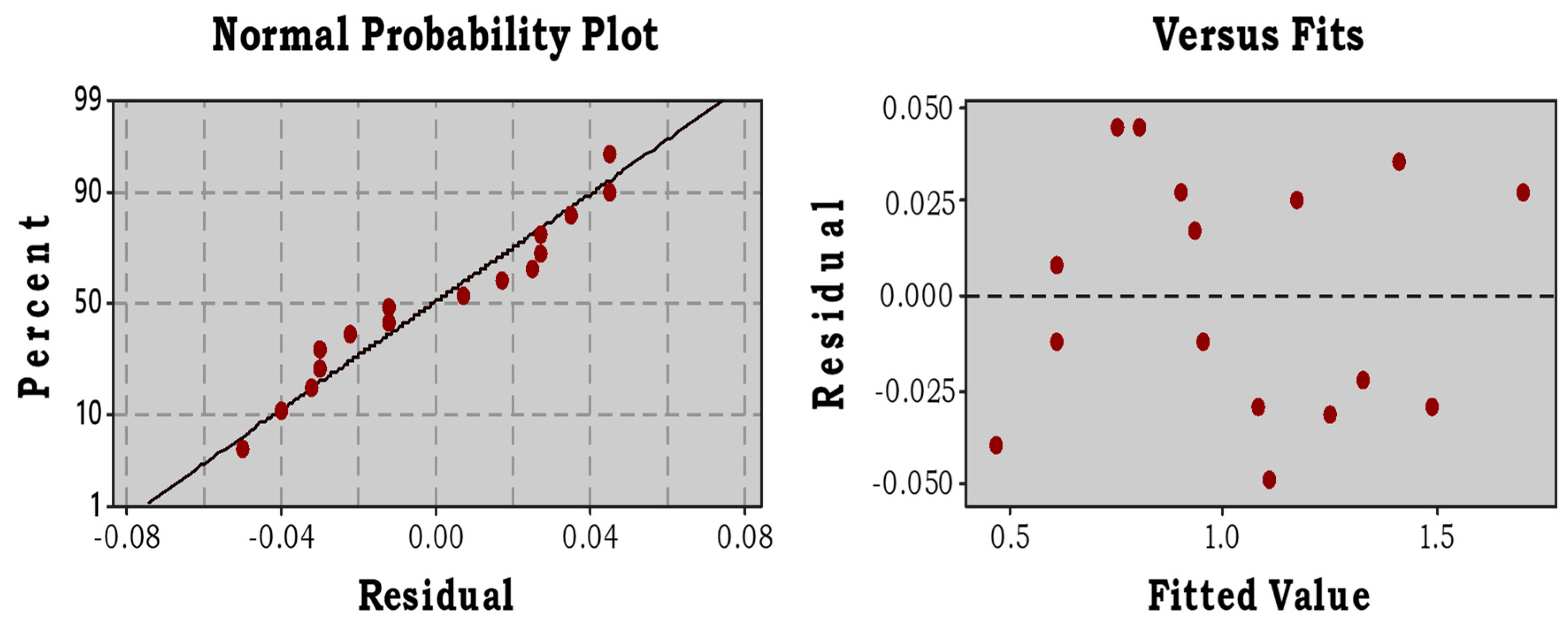
3.1. Modelling of Process Parameters

To validate the data generated through machining test experiments, some statistical tests like normal probability, residual analysis, etc., were initially performed from a statistical point of view. It can be observed from Figure 4 that in the first analysis, the residuals data was distributed normally, except for a few data points that show some random behaviour concerning the lower and upper end. It is quite obvious that this type of scattering is always appearing in the experimental data. Furthermore, the shape of data along with the normal line is an “S-shape”. This also confirms that the data generated through experimental runs were statistically validated. Additionally, to further validate the experimental data set, it was subjected to the studentised residual method used for statistical significance tests. In this method, the standard deviation was used for the estimation and detection of discrepant data. From this analysis, it is noted that the values of standard deviation lay significantly between ±3 since from the mean the significant level was below 0.005 as shown in Figure 4. This confirms the acceptability of the model for further analysis.

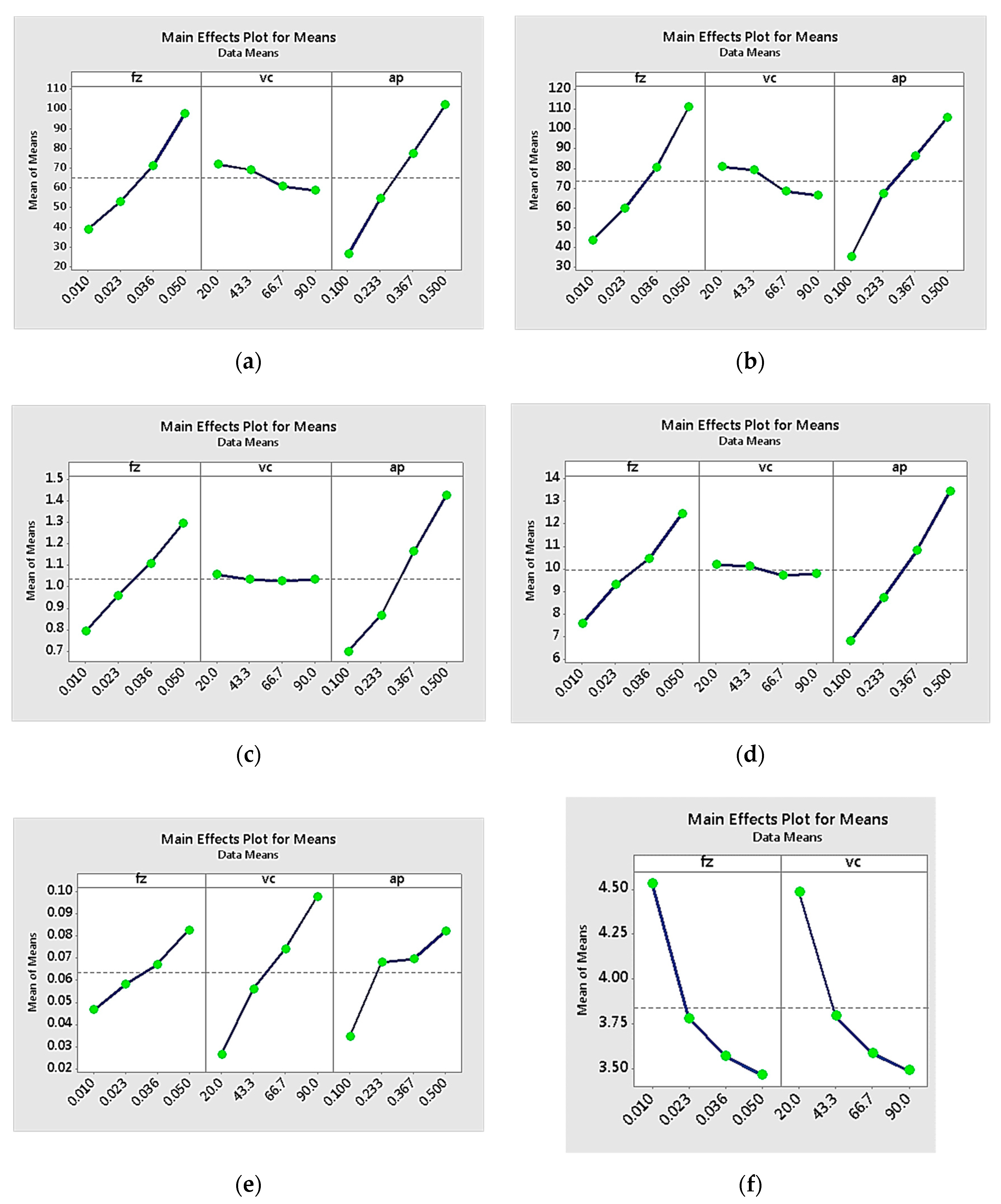
3.2. Effect of Process Parameters on Process Responses (Surface Roughness, Cutting Forces, Power, and Cost)

It is significant to find out which effect each process parameter has on the various responses of the experimental procedure, namely the values of each cutting force component, the surface roughness indicator values, the power consumption, and machining cost. After the statistical analysis was performed on the experimental data, taking into consideration that the experiment work was designed using the Taguchi method, the graphs of the main effects for the mean values of the responses were created as depicted in Figure 5a,f.
Figure 5a,b, the relation between the components of cutting force and parameters of the slot milling process is depicted in the form of the main effects plot. The total forces recorded during slot milling are equal to the sum of all the interactions occurring from the engagement of the cutting tool edges and the workpiece. These forces are proportional to the cutting area and also dependent on the thermomechanical properties of the workpiece and cutting tool material. The cutting forces are also a function of the resistance of the workpiece material to the imposed deformation and contact friction during cutting processes. It can be noted that Fx force components values increased when feed per tooth and radial depth of cut increase, whereas a slight decrease is observed when cutting speed increased. These trends can be justified, based on the characteristics of the slot end milling process. The cutting parameters directly affected the process kinematics and contact conditions between the cutting tool and workpiece and subsequently physical phenomena occurring during the process. When cutting speed increases, lower cutting forces are observed and material removal is enhanced, as the tendency of built-up edge formation, which is more common at low and medium speeds, leading to unstable cutting and higher cutting forces, is less significant [45,46,47,48]. Moreover, the increase of cutting temperature causes softening of workpiece material up to a certain degree, and thus, cutting resistance becomes lower. Furthermore, the increase of feed and radial depth of cut values leads to more intense cutting conditions. More specifically, when the cutting area, i.e., the uncut chip cross-section and tool-chip contact length increase, the material removed per revolution and consequently chip load are larger, and finally higher cutting forces are observed [45,46,47,49,50,51,52]. Feed per tooth and radial depth of cut were identified as the most influential parameters regarding Fx, implying that the regulation of cutting force could be effectively conducted mainly by adjusting these two parameters, whereas cutting speed was shown to be considerably less important within the selected parameter values’ range. The same trends are observed also in the case of Fy force component. Hence for sustainable machining and optimum cutting forces, it is important to ensure that the process mechanism was dominated by shearing. Ploughing and rubbing mechanisms at the tool-workpiece contact interface should be avoided by ensuring that the ratio of the undeformed chip thickness to the cutting-edge radius is equal to 1 [53]. However, if this ratio is less or more than unity, the tendency of friction will set in and increase the cutting forces.
Regarding Ra and Rt surface roughness indicators, the analysis of the experimental results, displayed in Figure 5c,d, respectively, revealed that feed per tooth and radial depth of cut had a considerable impact on Ra and Rt values, with Ra and Rt increasing with increase feed per tooth and ap values, whereas cutting speed played a less significant role for values within the selected range. Furthermore, it is to be noted that the results indicate that appropriate regulation of process parameters could result in a considerably superior quality of the milled slot surface, as low feed per tooth and radial depth of cut values led to Ra values much lower than 1 μm, with the lowest value being 0.43 μm. These trends could again be justified due to the characteristics of the slot milling process. Due to the specific kinematics of the slot end milling process, increased feed leads to deterioration of surface quality, as the distance between the successive marks formed by the cutting tool increases [49,54]. These results have been confirmed by both theoretical and detailed 3D measurements in the relevant literature [55,56]. Increased cutting speed leads to lower surface roughness, as build-up edge formation is less possible to occur in higher cutting speeds and then, surface quality is not so severely affected by it [46,54]. It is worth noting that, depending on the cutting speed range employed for the experiments, surface roughness is a non-monotonic function of cutting speed, but the general trend, i.e., the decrease of surface roughness for higher cutting speeds, remains the same [50]. It is to be noted that higher radial depth of cut also leads to higher values of surface roughness, as it leads to an increase of vibrations, in conjunction with cutting speed values [57].
Although maintaining surface quality at sufficiently high levels is a significant objective of the machining process, other significant objectives should be attained to achieve high productivity at acceptable costs and relatively low power consumption. Thus, the results regarding consumed power and machining cost for each experiment were subsequently analysed. Regarding power consumption, it becomes obvious from Equation (1) that an increase of cutting force and cutting speed lead to larger power consumption. This is directly observed in Figure 5e as cutting speed is shown to be the dominant factor that affects power consumption, with fz and ap also contributing to the increase of power consumption as their values increase, a finding that is consistent with the trends described in the relevant literature [58]. This behaviour can be anticipated from the results depicted in Figure 5a,b, as higher levels of both feed per tooth and radial depth of cut values increase the values of cutting force. The importance of each process parameter on the cost of the machining process was analysed with the main effects plot depicted in Figure 5f. As was anticipated, higher feed per tooth and cutting speed values led to a decrease of machining cost, because they had a direct impact on the machining time. As feed speed vf was equal to fz·n·z, with n representing the spindle speed in rpm and z the number of flutes of the end mill, and n was proportional to the cutting speed, an increase of these two process parameters increased vf and so decreased machining time and machining cost. The impact that the depth of cut had on the machining cost is not depicted in Figure 5f, as according to the methodology employed and the experimental conditions (all experiments were carried out in single machining passes), ap was not included in the calculations. From the aforementioned results, it is important to underline that the influence of process parameters was not the same for each of the quantities that were analysed; thus, a multiobjective optimisation method must be applied for the determination of optimum process parameter values to achieve a suitable compromise between all desired goals.
After the influence of each process parameter on cutting force components, surface roughness indicators, power consumption, and machining cost were determined, multiple regression analysis was employed to establish appropriate equations relating the process parameters with the aforementioned responses. Multiple regression analysis could effectively provide a quantitative representation of the experimental results, which will be particularly useful in studying the multiparametric and multiobjective problem. For the development of the regression equations, preliminary work was conducted to include only the statistically important terms and the criterion for the selection of the appropriate equation form was the coefficient of determination R2, and the adjusted-R2 values. The general form of the regression equation could include all process parameters and their squares and a constant term, but in some cases, a simpler equation can be sufficient. In the case of power consumption and machining cost, this type of equation provided less accurate results and so a general exponential function was chosen instead. In these two cases, the mean square error (MSE) and standard error of the regression S were chosen as criteria rather than R2. The regression equations for each response are as follows:
Cutting force, x-component (R2 = 94.41%, R2-adjusted = 93.01%):
Fx = −23.17 + 1458·fz − 0.2036·vc + 187.0·ap
Cutting force, y-component (R2 = 92.49%, R2-adjusted = 90.62%):
Fy = −15.6 + 1690·fz − 0.237·vc + 173.3·ap
Surface roughness indicator Ra (R2 = 98.27%, R2-adjusted = 97.84%):
Ra = 0.1248 + 12.523·fz + 1.8593·ap
Surface roughness indicator Rt (R2= 98.74%, R2-adjusted = 98.43%):
Rt = 1.808 + 119.11·fz + 16.607·ap
Power consumption Pc (MSE = 0.00012, S = 0.0109):
Pc = 0.02303·fz0.602·vc1.015·ap0.686
Machining cost Ci (MSE = 0.066, S = 0.256):
Ci = 3.93523·fz−0.184·vc−0.185
It can be observed that each of the developed regression equations is consistent with the characteristics of the slot end milling process. Regarding cutting force components, the regression equations directly reflect the physics of the milling process as described in the present subsection. More specifically, the positive sign of the fz and ap terms in both Equations (3) and (4), indicating an increase of cutting forces with an increase of feed per tooth and depth of cut values, and the negative effect of cutting speed, indicated by the negative sign of the respective term comply with the trends observed in Figure 5. Similarly, according to Equations (5) and (6), it becomes obvious that both depth of cut and feed lead to higher surface roughness, as the sign of the respective terms is positive. Moreover, the power-law equation coefficients of Equation (7) are consistent with the described effects of process parameters on power consumption, with an increase of each parameter leading to an increase in the power consumption. The effect of feed per tooth and cutting speed on machining cost is reflected in the negative power law coefficients of Equation (8), related to an inversely proportional relationship between the two parameters and machining cost.

3.3. Optimisation

After analysing the results, the next procedure adopted in this work was the optimisation of process parameters. The details regarding the desirability-based optimisation method were discussed in the previous section. The optimisation model was developed based upon the evaluating criteria of responses, i.e., smaller is better, nominal is better, and higher is better. After selecting the evaluating criteria, the combination having the highest desirability value was considered as the optimal parameter. As the optimum result in the slot, milling was obtained when the cutting forces, surface roughness, power consumption, machining cost, and carbon emissions remained at relatively low levels, the goal of the optimisation process was the minimisation of all these responses. Thus, the cutting forces, surface roughness, cutting power, machining cost, and carbon emissions were selected under the criteria of smaller the better, whereas, feed rate, cutting speed, and depth of cut was selected within the range. Table 6 reveals the results obtained after the optimisation was performed. The three sets of combinations were derived from the desirability approach and the higher value of desirability was selected as the optimal parameter.

4. Conclusions

This work presented the slot milling of hardened and difficult to cut the AISI O1 steel alloy to investigate the dominating effect of feed, cutting speed, and depth of cut on surface roughness on one hand and the cutting force, power, and machining cost on the other. Consideration was also given to the use of the sustainability assessment criterion to obtain the optimal and stable characteristics for the eco-benign machining of hardened steel. The following can be inferred from this work:
  • For resource efficiency, the optimum parameters for eco-benign machining of the AISI O1 steel alloy should be set at 0.01 mm/tooth, 20 m/min, and 0.1 mm for feed rate, cutting speed, and depth of cut respectively. This selection of parameters would reduce the trial and error process involved in determining optimum parameters for machining that machinists undergo.
  • The power consumption model and the machining cost model could be adopted as generic for slot milling and milling operations for difficult to cut materials.
  • Both linear and non-linear laws were revealed by regression analysis of the influence of feed (fz), cutting speed (vc), cutting of depth (ap) on surface roughness (Ra, Rt), cutting force (Fx, Fy), cutting power (Pc), machining cost (Ci), and carbon dioxide (Ene), which can be easily integrated into CNC machines. Each of the developed regression equations was consistent with the characteristics of the slot milling process. Cutting forces increased with increasing feed per tooth and depth of cut and decrease with increasing cutting speed. Likewise, the depth of cut and feed will result in higher surface roughness. Increasing feed per tooth, depth of cut, and cutting speed increases power consumption. Increasing feed per tooth and cutting speed results in lower machining costs.
  • The sustainability assessment model adopted produced the optimal and stable levels of design variables when machining AISI O1 tool steel with the P1 values set to “1” at a cutting speed of 20 m/min or 43.3 m/min and “2” at a cutting speed of 66.7 m/min or 90 m/min.

Author Contributions

Conceptualisation, A.P.M., N.E.K., M.M., D.Y.P., M.K.G.; Methodology, A.P.M., N.E.K., M.M., D.Y.P., M.K.G.; Software, A.P.M., N.E.K., M.K.; Validation, A.P.M., N.E.K.; Analysis, A.P.M., N.E.K., M.K.G.; Investigation, A.P.M., N.E.K., M.M., D.Y.P., M.K.G., H.H.; Resources, A.P.M., N.E.K., M.K.G.; Data Curation, A.P.M., N.E.K., D.Y.P., M.K.G.; Writing—Original Draft Preparation A.P.M., N.E.K., M.M., D.Y.P., M.K.G., H.H., N.K., V.A.B., S.S.; Writing—Review and Editing, A.P.M., N.E.K., M.M., D.Y.P., M.K.G., H.H., N.K., V.A.B., S.S.; Visualisation, A.P.M., N.E.K., D.Y.P., M.K.G., H.H.; Supervision, A.P.M., M.M., M.K.G., D.Y.P.; Project Administration, A.P.M., D.Y.P.; Funding Acquisition, A.P.M., M.M., D.Y.P. All authors have read and agreed to the published version of the manuscript.

Funding

This research received no external funding.

Acknowledgments

The research was also supported through Act 211 Government of the Russian Federation, contract Nr 02.A03.21.0011.

Conflicts of Interest

The authors declare no conflict of interest.

Nomenclature

RaArithmetic average value of surface roughness
EneCarbon dioxide
Fx, FyComponents of cutting forces in the direction of the x, y axes
dCutter diameter
PcCutting power (Power consumption)
vcCutting speeds
apDepth of cut
fzFeed per tooth
vfFeed speed
CiMachining cost
lMachining length
T’Machining time in face milling
k’Represents the setup insert
CInThe cost of Insert
CMhThe cost of machining hour
CToolhThe cost of Tool holder
zThe number of cutting inserts
CToolminThe tool cost per minute
LTToolhThe tool holder life
CwThe unit cost of workpiece
TTool life
RtTotal height of the roughness profile

References

  1. Vatavuk, J.; Totten, G.E.; Nucci, J.E.; Albano, L.L.M.; Canale, L.D.C.F. Comparative impact behavior of high-C steel after conventional quenching, tempering, and austempering. Mater. Perform. Charact. 2016, 5, 227–238. [Google Scholar] [CrossRef]
  2. Brar, M.S.; Simha, C.H.M. High strain rate compression and tension response of high hard tool steel. J. Phys. IV France 2000, 10, 611–615. [Google Scholar] [CrossRef]
  3. Rosales, I.; Martinez, H.; Guardian, R. Mechanical performance of thermally post-treated ion-nitrided steels. Appl. Surf. Sci. 2016, 371, 576–582. [Google Scholar] [CrossRef]
  4. Bourithis, L.; Papadimitriou, G.D.; Sideris, J. Comparison of wear properties of tool steels AISI D2 and O1 with the same hardness. Tribol. Int. 2006, 39, 479–489. [Google Scholar] [CrossRef]
  5. Kataria, R.; Kumar, J. A comparison of the different multiple response optimization techniques for turning operation of AISI O1 tool steel. J. Eng. Res. 2014, 2, 161–184. [Google Scholar] [CrossRef]
  6. Tamilarasan, A.; Marimuthu, K.; Renugambal, A. Investigations and optimization for hard milling process parameters using hybrid method of RSM and NSGA-II. Rev. Tec. De La Fac. De Ing. Univ. Del Zulia 2016, 39, 41–54. [Google Scholar]
  7. Navas, V.G.; García-Rosales, C.; Sevillano, J.G.; Ferreres, I.; Marañón, J.A. Hard turning plus grinding-a combination to obtain good surface integrity in AISI O1 tool steel machined parts. Mach. Sci. Technol. 2008, 12, 15–32. [Google Scholar] [CrossRef]
  8. Pereira, R.B.D.; Leite, R.R.; Alvim, A.C.; Paiva, A.P.D.; Ferreira, J.R.; Davim, J.P. Multi-objective robust optimization of the sustainable helical milling process of the aluminum alloy Al 7075 using the augmented-enhanced normalized normal constraint method. J. Clean. Prod. 2017, 152, 474–496. [Google Scholar] [CrossRef]
  9. Liu, Z.Y.; Li, C.; Fang, X.Y.; Guo, Y.B. Cumulative energy demand and environmental impact in sustainable machining of inconel superalloy. J. Clean. Prod. 2018, 181, 329–336. [Google Scholar] [CrossRef]
  10. Pervaiz, S.; Kannan, S.; Kishawy, H.A. An extensive review of the water consumption and cutting fluid based sustainability concerns in the metal cutting sector. J. Clean. Prod. 2018, 197, 134–153. [Google Scholar] [CrossRef]
  11. Yan, J.; Li, L. Multi-objective optimization of milling parameters-the trade-offs between energy, production rate and cutting quality. J. Clean. Prod. 2013, 52, 462–471. [Google Scholar] [CrossRef]
  12. Singh, A.; Philip, D.; Ramkumar, J.; Das, M. A simulation based approach to realize green factory from unit green manufacturing processes. J. Clean. Prod. 2018, 182, 67–81. [Google Scholar] [CrossRef]
  13. Cao, H.; Li, H.; Cheng, H.; Luo, Y.; Yin, R.; Chen, Y. A carbon efficiency approach for life-cycle carbon emission characteristics of machine tools. J. Clean. Prod. 2012, 37, 19–28. [Google Scholar] [CrossRef]
  14. Lu, Q.; Zhou, G.; Zhao, F.; Ren, Y.; Li, L.; Luan, X. Sutherland JW. Topology optimization of oilstone components considering carbon emissions associated with honing processes. J. Clean. Prod. 2019, 225, 181–195. [Google Scholar] [CrossRef]
  15. Camposeco-Negrete, C.; de Dios Calderón-Nájera, J. Optimization of energy consumption and surface roughness in slot milling of AISI 6061 T6 using the response surface method. Int. J. Adv. Manuf. Technol. 2019, 103, 4063–4069. [Google Scholar] [CrossRef]
  16. Zhou, G.; Lu, Q.; Xiao, Z.; Zhou, C.; Tian, C. Cutting parameter optimization for machining operations considering carbon emissions. J. Clean. Prod. 2019, 208, 937–950. [Google Scholar] [CrossRef]
  17. Sihag, N.; Sangwan, K.S. Development of a Multi-criteria Optimization Model for Minimizing Carbon Emissions and Processing Time during Machining. Procedia CIRP 2018, 69, 300–305. [Google Scholar] [CrossRef]
  18. Wang, M.-Y.; Chang, H.-Y. Experimental study of surface roughness in slot end milling AL2014-T6. Int. J. Mach. Tools Manuf. 2004, 44, 51–57. [Google Scholar] [CrossRef]
  19. Niknam, S.A.; Songmene, V. Simultaneous optimization of burrs size and surface finish when milling 6061-T6 aluminium alloy. Int. J. Precis. Eng. Manuf. 2013, 14, 1311–1320. [Google Scholar] [CrossRef]
  20. Pimenov, D.Y. Experimental research of face mill wear effect to flat surface roughness. J. Frict. Wear 2014, 35, 250–254. [Google Scholar] [CrossRef]
  21. Duboust, N.; Ghadbeigi, H.; Pinna, C.; Ayvar-Soberanis, S.; Collis, A.; Scaife, R.; Kerrigan, K. An optical method for measuring surface roughness of machined carbon fibre-reinforced plastic composites. J. Compos. Mater. 2016, 51, 289–302. [Google Scholar] [CrossRef] [Green Version]
  22. Niknam, S.A.; Balazinski, M.; Songmene, V. To characterize and optimize the surface quality attributes in slot milling operation. Int. J. Adv. Manuf. Technol. 2017, 93, 727–746. [Google Scholar] [CrossRef]
  23. Wang, C.; Wen, L.; Ming, W.; An, Q.; Chen, M. Experimental study on effects of fiber cutting angle in milling of high-strength unidirectional carbon fiber–reinforced polymer laminates. Proc. Inst. Mech. Eng. Part B J. Eng. Manuf. 2018, 232, 1813–1824. [Google Scholar] [CrossRef]
  24. Pimenov, D.Y.; Hassui, A.; Wojciechowski, S.; Mia, M.; Magri, A.; Suyama, D.I.; Bustillo, A.; Krolczyk, G.; Gupta, M.K. Effect of the Relative Position of the Face Milling Tool towards the Workpiece on Machined Surface Roughness and Milling Dynamics. Appl. Sci. 2019, 9, 842. [Google Scholar] [CrossRef] [Green Version]
  25. Jebaraj, M.; Pradeep Kumar, M. Effect of cryogenic CO 2 and LN 2 coolants in milling of aluminum alloy. Mater. Manuf. Process. 2019, 34, 511–520. [Google Scholar] [CrossRef]
  26. Yeganefar, A.; Niknam, S.A.; Asadi, R. The use of support vector machine, neural network, and regression analysis to predict and optimize surface roughness and cutting forces in milling. Int. J. Adv. Manuf. Technol. 2019, 105, 951–965. [Google Scholar] [CrossRef]
  27. Pimenov, D.Y.; Abbas, A.T.; Gupta, M.K.; Erdakov, I.N.; Soliman, M.S.; El Rayes, M.M. Investigations of surface quality and energy consumption associated with costs and material removal rate during face milling of AISI 1045 steel. Int. J. Adv. Manuf. Technol. 2020, 107, 3511–3525. [Google Scholar] [CrossRef]
  28. Balogun, V.A.; Edem, I.F.; Bonney, J.; Ezeugwu, E.; Mativenga, P.T. Effect of Cutting Parameters on Surface Finish when Turning Nitronic 33 Steel alloy. Int. J. Sci. Eng. Res. 2015, 6, 1–9. [Google Scholar]
  29. Osman, K.A.; Yılmaz, V.; Ünver, H.Ö.; Şeker, U.; Kılıç, S.E. Slot milling of titanium alloy with hexagonal boron nitride and minimum quantity lubrication and multi-objective process optimization for energy efficiency. J. Clean. Prod. 2020, 258, 120739. [Google Scholar] [CrossRef]
  30. Muñoz-Escalona, P.; Shokrani, A.; Dhokia, V.; Imani-Asrai, R.; Newman, S.T. A surface roughness and power consumption analysis when slot milling austenitic stainless steel in a dry cutting environment. Lect. Notes Mech. Eng. 2013, 7, 637–649. [Google Scholar] [CrossRef]
  31. Liu, N.; Zhang, Y.F.; Lu, W.F. A hybrid approach to energy consumption modelling based on cutting power: A milling case. J. Clean. Prod. 2015, 104, 264–272. [Google Scholar] [CrossRef]
  32. Liu, N.; Wang, S.B.; Zhang, Y.F.; Lu, W.F. A novel approach to predicting surface roughness based on specific cutting energy consumption when slot milling Al-7075. Int. J. Mech. Sci. 2016, 118, 13–20. [Google Scholar] [CrossRef]
  33. Edem, I.F.; Balogun, V.A. Sustainability analyses of cutting edge radius on specific cutting energy and surface finish in side milling processes. Int. J. Adv. Manuf. Technol. 2018, 95, 3381–3391. [Google Scholar] [CrossRef]
  34. Pimenov, D.Y.; Bustillo, A.; Mikolajczyk, T. Artificial intelligence for automatic prediction of required surface roughness by monitoring wear on face mill teeth. J. Intell. Manuf. 2018, 29, 1045–1061. [Google Scholar] [CrossRef] [Green Version]
  35. Abbas, A.T.; Pimenov, D.Y.; Erdakov, I.N.; Mikolajczyk, T.; Soliman, M.S.; El Rayes, M.M. Optimization of cutting conditions using artificial neural networks and the Edgeworth-Pareto method for CNC face-milling operations on high-strength grade-H steel. Int. J. Adv. Manuf. Technol. 2019, 105, 2151–2165. [Google Scholar] [CrossRef] [Green Version]
  36. Abbas, A.T.; Pimenov, D.Y.; Erdakov, I.N.; Taha, M.A.; El Rayes, M.M.; Soliman, M.S. Artificial intelligence monitoring of hardening methods and cutting conditions and their effects on surface roughness, performance, and finish turning costs of solid-state recycled aluminum alloy 6061 chips. Metals 2018, 8, 394. [Google Scholar] [CrossRef] [Green Version]
  37. Abbas, A.T.; Pimenov, D.Y.; Erdakov, I.N.; Taha, M.A.; Soliman, M.S.; El Rayes, M.M. ANN Surface Roughness Optimization of AZ61 Magnesium Alloy Finish Turning: Minimum Machining Times at Prime Machining Costs. Materials 2018, 11, 808. [Google Scholar] [CrossRef] [Green Version]
  38. Pusavec, F.; Krajnik, P.; Kopac, J. Transitioning to sustainable production—Part I: Application on machining technologies. J. Clean. Prod. 2010, 18, 174–184. [Google Scholar] [CrossRef]
  39. Krolczyk, G.M.; Maruda, R.W.; Krolczyk, J.B.; Wojciechowski, S.; Mia, M.; Nieslony, P.; Budzik, G. Ecological trends in machining as a key factor in sustainable production—A review. J. Clean. Prod. 2019, 218, 601–615. [Google Scholar] [CrossRef]
  40. Krolczyk, G.M.; Nieslony, P.; Maruda, R.W.; Wojciechowski, S. Dry cutting effect in turning of a duplex stainless steel as a key factor in clean production. J. Clean. Prod. 2017, 142, 3343–3354. [Google Scholar] [CrossRef]
  41. Hegab, H.A.; Darras, B.; Kishawy, H.A. Towards sustainability assessment of machining processes. J. Clean. Prod. 2018, 170, 694–703. [Google Scholar] [CrossRef]
  42. Narita, H.; Desmira, N.; Fujimoto, H. Environmental burden analysis for machining operation using LCA method. Manuf. Syst. Technol. New Front. 2008, 65–68. [Google Scholar] [CrossRef]
  43. Khanna, N.; Shah, P.; Agrawal, C.; Pusavec, F.; Hegab, H. Inconel 718 machining performance evaluation using indigenously developed hybrid machining facilities: Experimental investigation and sustainability assessment. Int. J. Adv. Manuf. Technol. 2020, 106, 4987–4999. [Google Scholar] [CrossRef]
  44. Khanna, N.; Shah, P.; Maruda, R.W.; Krolczyk, G.M.; Hegab, H. Experimental investigation and sustainability assessment to evaluate environmentally clean machining of 15-5 PH stainless steel. J. Manuf. Process. 2020, 56, 1027–1038. [Google Scholar] [CrossRef]
  45. Xu, C.; Dou, J.; Chai, Y.; Li, H.; Shi, Z.; Xu, J. The relationships between cutting parameters, tool wear, cutting force and vibration. Adv. Mech. Eng. 2018, 10, 1–14. [Google Scholar] [CrossRef]
  46. Korkut, I.; Donertas, M.A. The influence of feed rate and cutting speed on the cutting forces, surface roughness and tool-chip contact length during face milling. Mater. Des. 2007, 28, 308–312. [Google Scholar] [CrossRef]
  47. Shi, K.; Dinghua, Z.; Junxue, R.; Changfeng, Y.; Xinchun, H. Effect of cutting parameters on machinability characteristics in milling of magnesium alloy with carbide tool. Adv. Mech. Eng. 2016, 8, 1–9. [Google Scholar] [CrossRef] [Green Version]
  48. Kaya, E.; Akyuz, B. Effects of cutting parameters on machinability characteristics of Ni-based superalloys: A review. Open Eng. 2017, 7, 330–342. [Google Scholar] [CrossRef]
  49. Subramanian, M.; Sakthivel, M.; Sooryprakash, K.; Sudharakan, R. Optimization of cutting parameters for cutting force in shoulder milling of Al7075-T6 using response surface methodology and genetic algorithm. Procedia Eng. 2013, 64, 690–700. [Google Scholar] [CrossRef] [Green Version]
  50. Begić-Hajdarević, Đ.; Čekić, A.; Kulenović, M. Effect of the cutting parameters on cutting forces in high speed face milling| [Utjecaj parametara obrade na sile rezanja pri visokobrzinskom Čeonom glodanju]. Teh. Vjesn. 2013, 20, 775–780. [Google Scholar]
  51. Ghoreishi, R.; Roohi, A.H.; Ghadikolaei, A.D. Analysis of the influence of cutting parameters on surface roughness and cutting forces in high speed face milling of Al/SiCMMC. Mater. Res. Express 2018, 5, 086521. [Google Scholar] [CrossRef]
  52. Subramanian, A.V.M.; Nachimuthu, M.D.G.; Cinnasamy, V. Assessment of cutting force and surface roughness in LM6/SiCp using response surface methodology. J. Appl. Res. Technol. 2017, 15, 283–296. [Google Scholar] [CrossRef]
  53. Balogun, V.A.; Edem, I.F.; Adekunle, A.A.; Mativenga, P.T. Specific energy based evaluation of machining efficiency. J. Clean. Prod. 2016, 116, 187–197. [Google Scholar] [CrossRef]
  54. Hayajneh, M.T.; Tahar, M.S.; Bluhm, J. A study of the effects of machining parameters on the surface roughness in end-milling process. Jordan J. Mech. Ind. Eng. 2007, 1, 1–5. [Google Scholar]
  55. Felhő, C.; Karpuschewski, B.; Kundrák, J. Surface roughness modelling in face milling. Procedia CIRP 2015, 31, 136–141. [Google Scholar] [CrossRef] [Green Version]
  56. Kundrák, J.; Felhő, C. Topography of the machined surface in high performance face milling. Procedia CIRP 2018, 77, 340–343. [Google Scholar] [CrossRef]
  57. Hernández-González, L.W.; Pérez-Rodríguez, R.; Quesada-Estrada, A.M.; Dumitrescu, L. Effects of cutting parameters on surface roughness and hardness in milling of AISI 304 steel. DYNA 2018, 85, 57–63. [Google Scholar] [CrossRef]
  58. Shnfir, M.; Olufayo, O.A.; Jomaa, W.; Songmene, V. Machinability study of hardened 1045 steel when milling with ceramic cutting inserts. Materials 2019, 12, 3974. [Google Scholar] [CrossRef] [Green Version]
Figure 1. End-mill used in the experiments.
Metals 10 01650 g001
Figure 2. (a) Dynamometer Kirstler Type 9257A and (b) workpiece on the machine tool.
Metals 10 01650 g002
Figure 3. Sustainable indicators.
Metals 10 01650 g003
Figure 4. Normal probability plot and residual plots for the Ra value.
Metals 10 01650 g004
Figure 5. Main effect plots for: (a) Fx force component, (b) Fy force component, (c) Ra, (d) Rt, (e) power consumption Pc, and (f) machining cost Ci.
Metals 10 01650 g005
Table 1. Chemical composition of the workpiece material.
C (%)Si (%)Mn (%)P (%)S (%)Cr (%)W (%)V (%)Fe (%)
0.960.221.080.0080.0040.450.410.09Balance
Table 2. Experimental factors and their levels.
Cutting ParameterLevel 1Level 2Level 3Level 4
Depth of cut (mm)0.10.2330.3670.5
Cutting speed (m/min)2043.366.790
Feed rate (mm/tooth)0.010.0230.0360.05
Table 3. Experimental results regarding milling parameters.
No. of ExperimentFeed per Tooth, fz (mm/tooth)Cutting Speed, vc (m/min)Cutting of Depth, ap (mm)Roughness, Ra (µm)Roughness, Rt (µm)Force, Fx (N)Force, Fy (N)Cutting Power, Pc (kW)Machining Cost, Ci ($)Carbon Dioxide, EneHigh-Speed Surface Exposure, P1
10.01200.10.434.9320250.0085.890.003051
20.0143.30.2330.66.823320.0234.440.008761
30.0166.70.3670.937.8743450.0494.010.018672
40.01900.51.210.770720.1063.800.040392
50.023200.2330.858.240520.0174.370.006481
60.02343.30.10.625.8724330.0233.740.008761
70.02366.70.51.3112.9383850.0923.550.035052
80.023900.3671.0510.265680.1003.460.03812
90.036200.3671.2211.4382920.0303.950.011431
100.03643.30.51.4614.061101120.0793.540.03011
110.03666.70.10.87.227380.0413.420.015622
120.036900.2330.959.165800.1183.370.044962
130.05200.51.7316.171451550.0513.730.019431
140.0543.30.3671.4513.771201400.0993.450.037721
150.0566.70.2331.0610.83901050.1143.360.043432
160.05900.10.949.135450.0663.320.025152
Table 4. Preliminary tests results regarding cutting force components.
No. of ExperimentForce, Fx (N)-1st ReplicationForce, Fy (N)-1st ReplicationForce, Fx (N)-2nd ReplicationForce, Fy (N)-2nd ReplicationForce, Fx (N)-3rd ReplicationForce, Fy (N)-3rd ReplicationAverage Force, Fx (N)Average Force, Fy (N)CVFx (%)CVFy (%)
120.625.619.624.819.824.620252.652.12
539.350.240.254.340.551.540521.564.03
863.764.266.171.565.268.365681.875.38
13146.3150.6150.2155.1138.5159.31451554.112.81
Table 5. Preliminary tests results regarding surface roughness indicators.
No. of ExperimentRa (μm)-1st ReplicationRt (μm)-1st ReplicationRa (μm)-2nd ReplicationRt (μm)-2nd ReplicationRa (μm)-3rd ReplicationRt (μm)-3rd ReplicationAverage Ra (μm)Average Rt (μm)CVRa (%)CVRt (%)
10.434.820.455.070.414.90.434.934.652.59
50.847.70.98.60.818.30.858.25.395.59
81.0410.31.019.61.110.71.0510.24.365.46
131.7515.71.7916.121.6516.71.7316.174.173.10
Table 6. Optimum parameters.
No. of ExperimentFeed per Tooth, f (mm/tooth)Cutting Speed, vc (m/min)Cutting of Depth, ap (mm)Roughness, Ra (µm)Roughness, Rt (µm)Force, Fx (N)Force, Fy (N)Cutting Power, Pc (kW)Machining Cost, Ci ($)Carbon Dioxide, EneDesirability Value
10.01220.20.424.8522220.0105.940.003170.999
20.01250.2330.454.9523240.0155.980.003250.9842
30.01220.2350.465.0125260.0135.80.003300.8425
Publisher’s Note: MDPI stays neutral with regard to jurisdictional claims in published maps and institutional affiliations.

