Article

Ball Spin Forming for Flexible and Partial Diameter Reduction in Tubes

1
Department of Mechanical and Intelligent Systems Engineering, The University of Electro-Communications, 1-5-1 Chofugaoka, Chofu, Tokyo 182-8585, Japan
2
Department of Electronics and Manufacturing, Advanced Manufacturing Research Institute, National Institute of Advanced Industrial Science and Technology (AIST), 1-2-1 Namiki, Tsukuba, Ibaraki 305-8564, Japan
*
Author to whom correspondence should be addressed.
Metals 2020, 10(12), 1627; https://doi.org/10.3390/met10121627
Submission received: 30 October 2020 / Revised: 27 November 2020 / Accepted: 2 December 2020 / Published: 4 December 2020
(This article belongs to the Special Issue Latest Hydroforming Technology of Metallic Tubes and Sheets)

Abstract

:
This paper proposed a new ball spin forming equipment, which can form a reduced diameter section on the halfway point of a tube. The effects of forming process parameters on the surface integrity and deformation characteristics of the product were investigated. The proposed method can reduce the diameter in the middle portion of the tube, and the maximum diameter reduction ratio was over 10% in one pass. When the feed pitch of the ball die was more than 2.0 mm/rev, spiral marks remained on the surface of tube. Torsional deformation, axial elongation and an increase in thickness appeared in the tube during the forming process. All of them were affected by the feed pitch and feed direction of the ball die, while they were not affected by the rotation speed of the tube. By sending the ball die towards the fixed part of the tube or by increasing the feed pitch, torsional deformation and elongation decreased, and the amount of thickening increased. When the tube was pressed perpendicularly to the axis without axial feed, a diameter reduction ratio of 21.1% was achieved without defects using a ball diameter of 15.9 mm. The polygonization of the tube was suppressed by reducing the pushing pitch. The ball spin forming has a high advantage in flexible diameter reduction processing on the halfway point of the tube for producing different diameter tubes.

1. Introduction

Tubes with variable diameters in the axial direction are in demand but it is costly to manufacture them. For instance, changing the tube diameter is achieved by connecting different diameter tubes using joints. It takes time and effort to connect, and in some cases, the connection often causes low airtightness. Therefore, the demand for different diameter continuous tubes (DDC tubes) and the process for DDC tubes without joining processes is high. There are some methods for manufacturing DDC tubes, such as U-O bending [1,2,3], and hydro forming [4,5]. U-O Bending is a processing method to form a tube from plate. Since these methods require tools whose shapes are uniquely related to the final shapes, they lack the flexibility of the product shape. Incremental forming is a flexible process. Incremental forming does not use die and can be used for a wide variety of product shapes [6,7,8]. Spinning is a typical incremental forming method [9,10]. Spinning with rollers does not require tools with unique shapes but needs repetitive processing because the diameter reduction rate per one processing is small due to the small area between the roller and tube, resulting in complex control of the roller position. In addition, the rigidity of the device is low due to the deformation of the roller struts when high stress is applied [11,12,13]. Therefore, Kanayama et al. developed a new method—”Ball spin forming” [14]. Ball spin forming is an efficient processing method that can solve the above problems. The essence of ball spin forming is the usage of “ball die”, which is a processing unit with three balls inside. The ball die can apply a large deformation to the tube at one pass as the balls are set inside a rigid and compact box. Kanayama et al. developed a planetary ball die for processing tube end and obtained tubes with smooth surface integrity. Kanayama at el. also reported that when the diameter reduction is performed using ball die, torsional deformation, axial elongation, and thickness increase occurred in tubes [15]. This type of die is applied in the manufacture of internally grooved tubes [16]. However, a ball die that cannot change the ball position in the radial direction can only process a simple shape. In this study, we developed a new ball forming ball die that can control the ball position in the radial direction of the tube for forming tubes with variable diameters in the axial direction. The new ball die combines the advantages of both spinning and planetary ball dies. The kinematics are the same as for roller spinning, but the rigidity and productivity of the equipment are improved, which solves the problems of spinning.
The structures of the developed ball die and deformed tube on the halfway portion are shown in Figure 1. Iron balls, which are constrained in the circumferential direction of the tube, are pushed in the radial direction of the tube by the rotation of the ball guide. The ball die travels along the tube axis while the tube rotates. As the result, the diameter reduction forming is performed by expanding the local concavity formed by the balls.
The remarkable feature of the new ball die, which is developed in this study, is that the balls move in the radial direction of the tube. The inner surface of the ball guide has the shape of a cam, and the shape realizes the control of the ball position in the tube-radial direction just by rotating the ball guide, to which a handle is connected. This feature enables flexible forming at the halfway point of the tube. This paper investigates the effect of parameters such as diameter reduction ratio, feed pitch, and rotational speed on the product shape and surface integrity. The experiments were carried out to the halfway point of the tube using the developed ball die, and the appropriate conditions were clarified for reducing the tube diameter without defects.

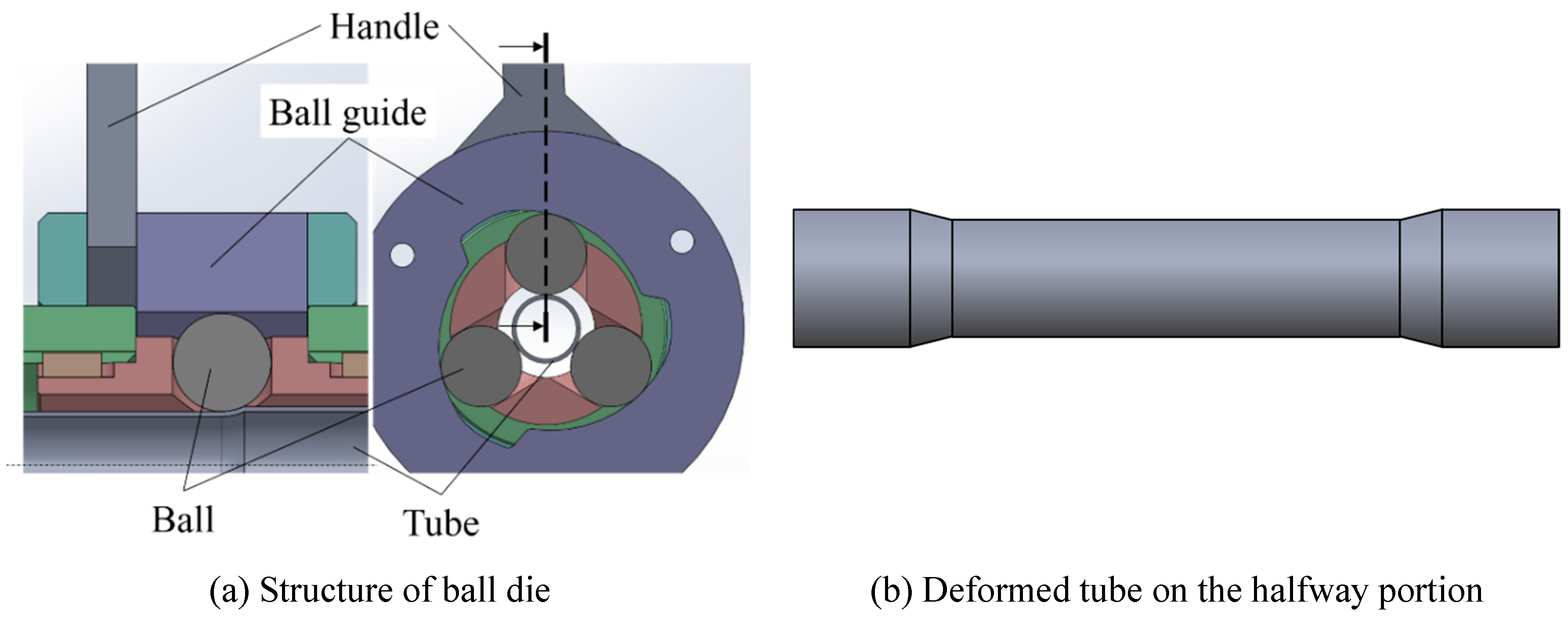
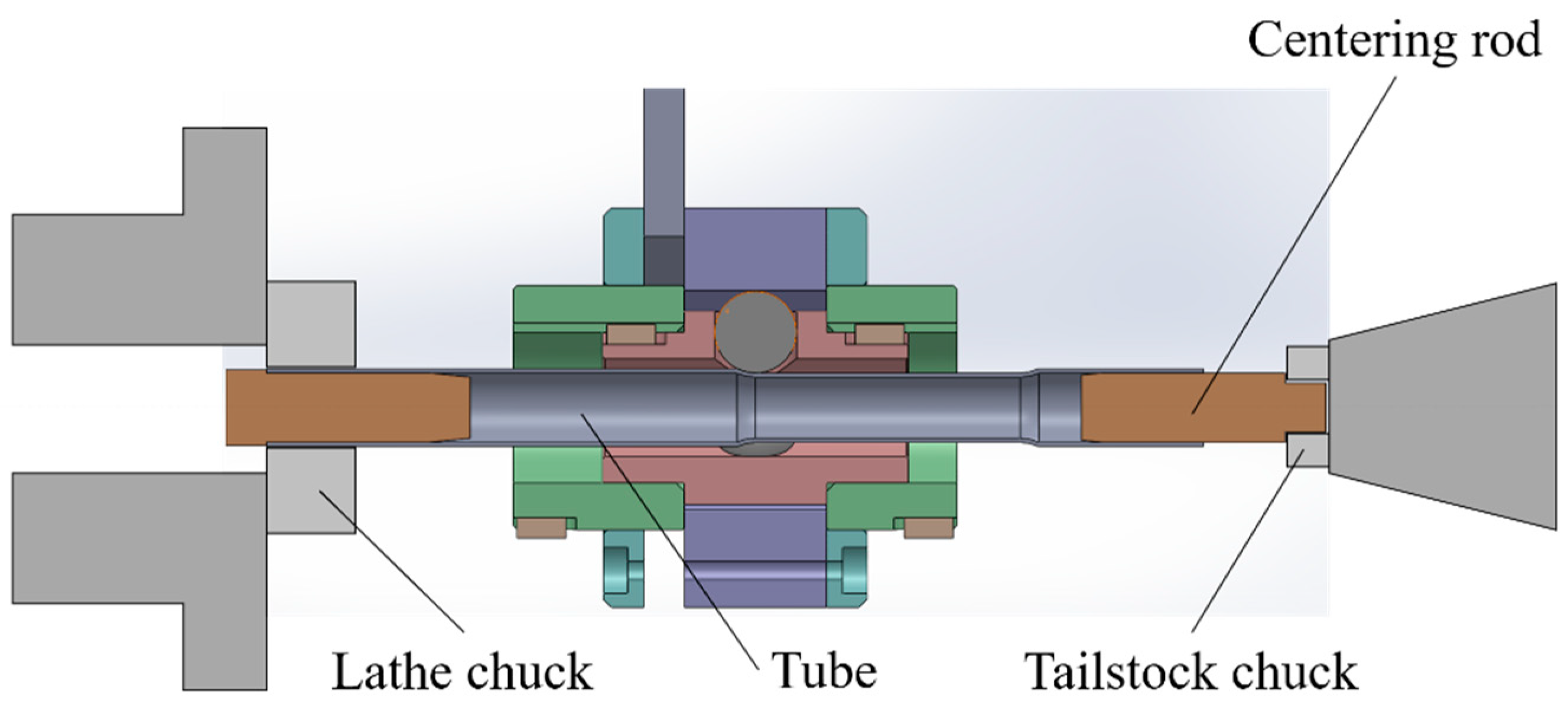
2. Experiment with a Small Ball Die for Lathe

2.1. Materials and Methods

The experimental material was an extruded tube of aluminum alloy 1050 (AA1050). The ball material was high carbon chrome bearing steel of SUJ2 (Japan Industrial Standard, JIS). The outer diameter and thickness of tubes were 19 and 0.9 mm, respectively. The outer diameter of the tool ball was 20 mm. Grease with molybdenum disulfide was applied to the surface of the tube as lubricant.
A schematic diagram of the experimental ball die is shown in Figure 2. The tube end was fixed to the chuck of the lathe. The ball die was mounted on the tool stand of the lathe, which moves in the axial direction automatically at a constant feed pitch f. The working conditions are shown in Table 1, including the diameter reduction ratio κD, the tube rotation speed n, and the feed pitch f. The procedure is as follows:
(1)
Push the balls into the tube surface without giving the feed pitch f.
(2)
Stop pushing the balls and feed the ball die at the constant feed pitch f.
(3)
Set the feed pitch to zero and release the ball from the tube.
Torsional deformation and elongation were evaluated by scribe lines. Scribe lines were marked on the tube surface in the longitudinal direction before forming as shown in Figure 3. The torsional deformation and elongation of the tube were measured by comparing the shape of scribe lines before and after forming. One end of the tube was chucked, while the other end was supported by a centering rod without axial constraint. That is to say, the constraint condition is different between the two tube ends. Therefore, the effect of moving direction of the ball die on the formability was investigated. The longitudinal section of the tube was observed using an optical microscope for evaluating the thickness distribution.

2.2. Results and Discussion

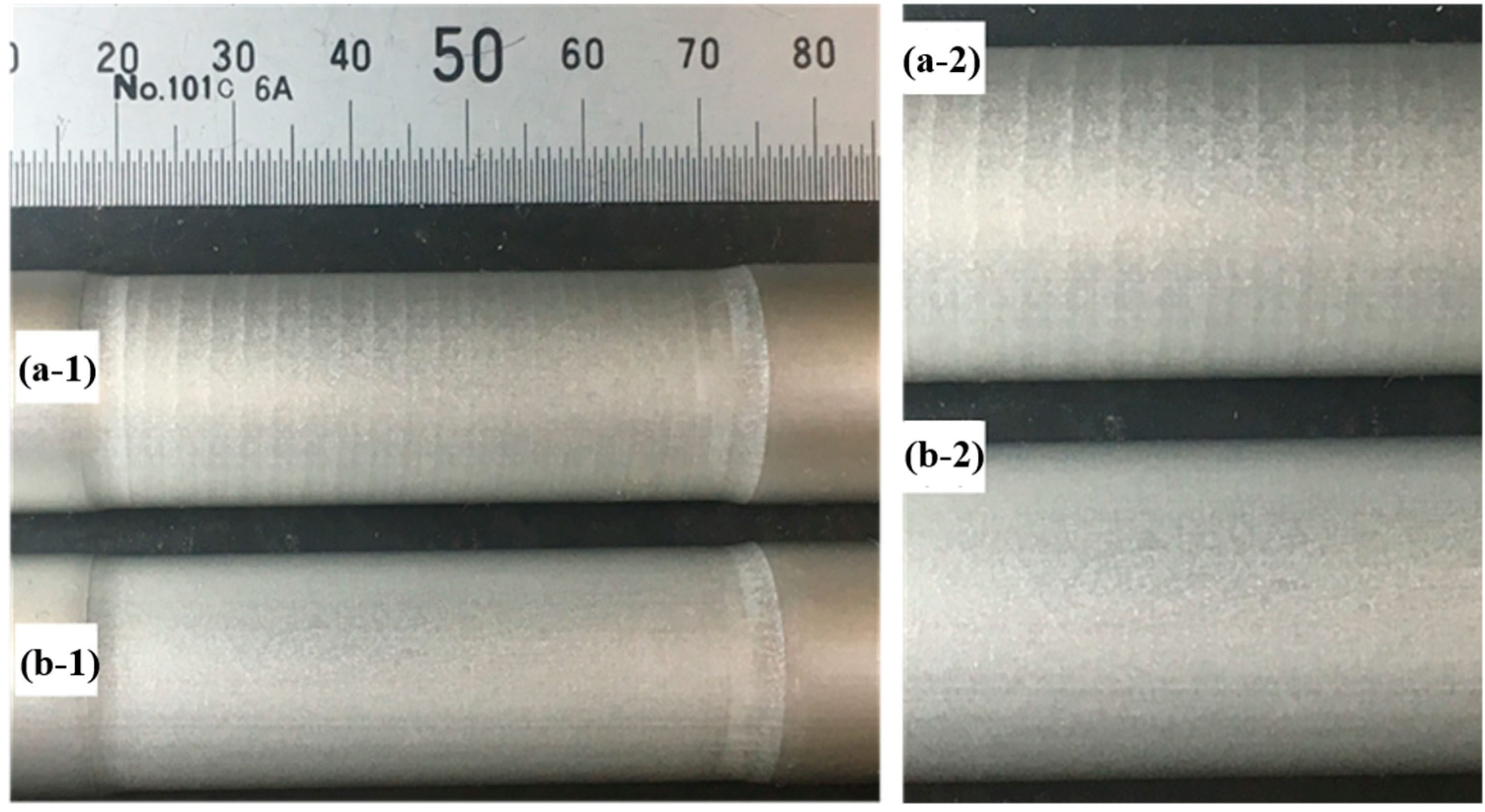
2.2.1. Effect of Feed Pitch on Surface Integrity

Figure 4 shows the tube surface after forming. When the feed pitch f exceeded 2.5 mm/rev, spiral marks appeared on the tube surface after the ball die passed, as shown in Figure 4a. When the feed pitch f was small, a smooth surface was obtained, as shown in Figure 4b. The effect of the rotational speed n on the surface integrity was small. Therefore, it is concluded that the formed surface integrity is determined by the feed pitch of the ball.

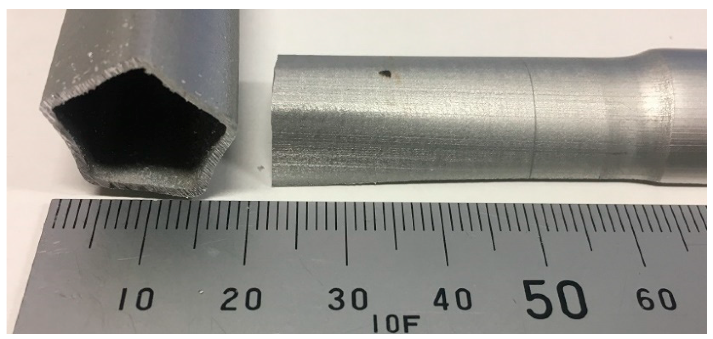
2.2.2. Forming Limit in One and Two-Step Processing

When processing was performed under a diameter reduction ratio κD of 15.8%, the tubes could not be formed into the target shape due to polygonization. In this case, the axis of the tube vibrated when the balls were excessively pushed to the tube. Then, the cross-section of the tube was deformed into a pentagonal shape as shown in Figure 5. In the case that κD was 10.5%, it was possible to push the ball to the tube at the beginning of the forming, but the pentagonal deformation occurred when the ball die proceeded to the middle portion of the tube.
On the other hand, two-step processing prevented the pentagonal deformation. In the first step, the tube was processed under a diameter reduction ratio κD of 5.3%. In the second step, the tube was processed again at the target diameter DT such as 17 or 16 mm. It is considered that the pentagonal deformation occurred because the tube axis was not held tightly against the large pushing force of the ball.

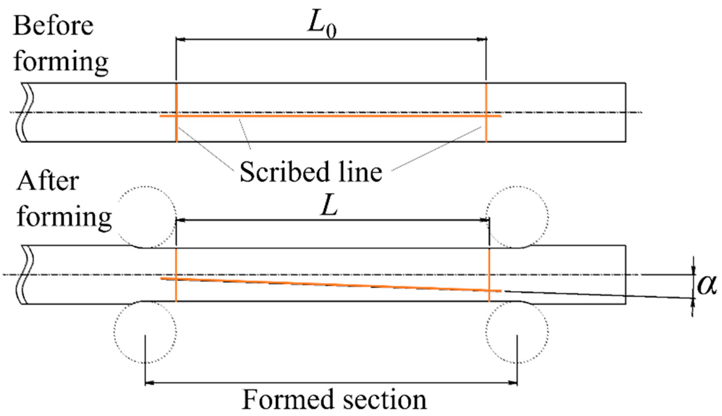
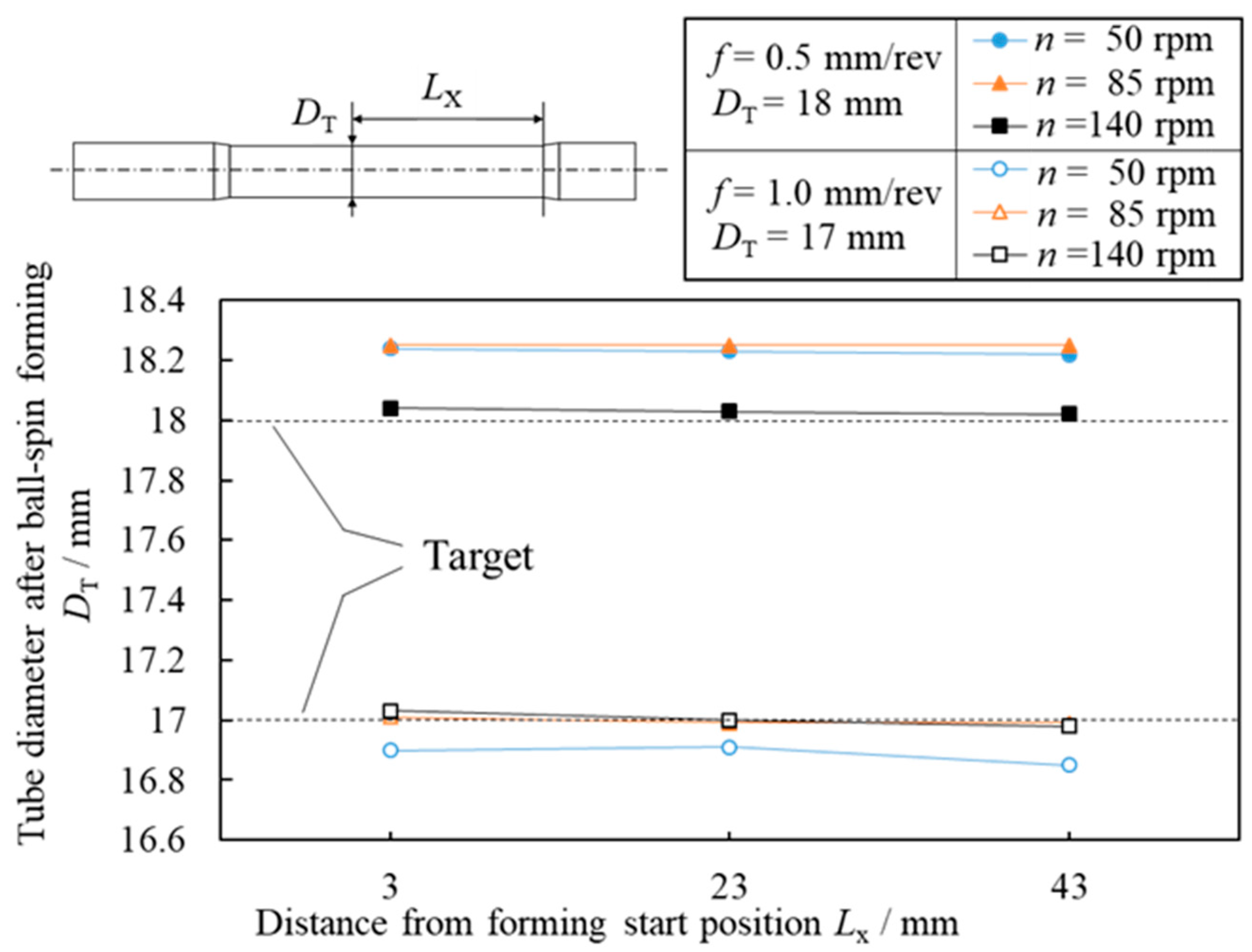
2.2.3. Dimensional Accuracy of Formed Tube

Figure 6 shows the distribution of the outer diameter of the formed tube in the processed section. The variation of the outer diameter in the processing section of the tube for 50 mm length was 0.04 mm or less in each processing condition. The deviation between the outer diameter of the formed tube and target was approximately 0.2 mm.

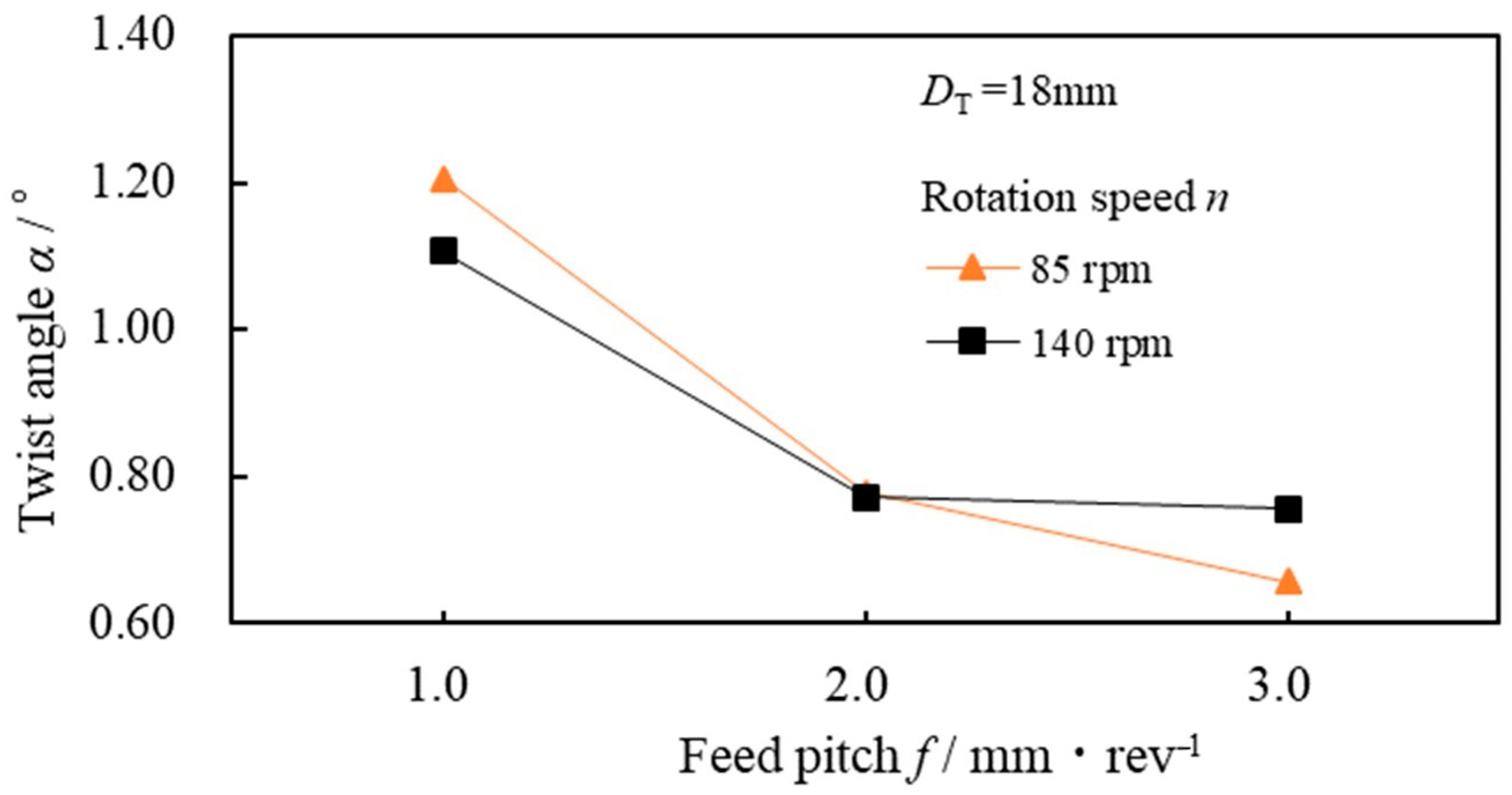
2.2.4. Torsional Deformation of Tube

When the ball die moved towards the free end in the processing, the formed portion of the tube was twisted. The effect of the feed pitch f on the twist angle α of the tube is shown in Figure 7. The twist angle α decreased with the increase in the feed pitch f as the increase in f lead to the decrease in tube-rotation number L/f. On the other hand, no twisting occurred when the ball die was moved towards the chucked end. Therefore, the effect of the feed direction of the ball die on the torsional deformation of the tube was significant.

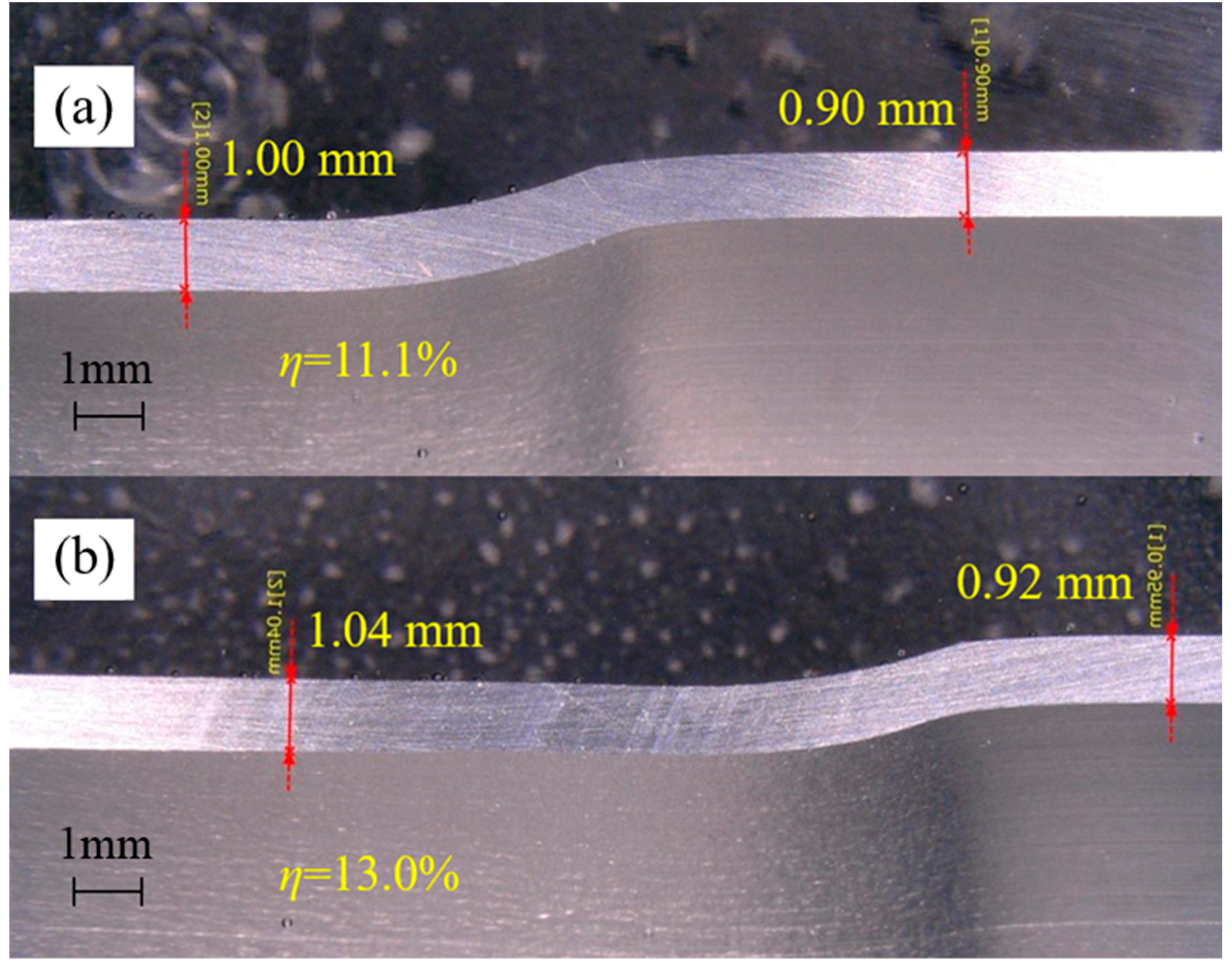
2.2.5. Thickness Increase in the Tube

Figure 8 shows the longitudinal section of the portion at the beginning of processing. The thickness increasing ratio η was defined as the following equation.
η = (tt0)/t0
where t0 and t were the tube thickness before and after forming, respectively. The thickness increasing ratio η showed the opposite tendency to the tube elongation rate. As mentioned in the previous section, the tube elongation was small in the case that the ball die moved from the free to chuck side. In Figure 8a, the thickness increasing ratio η was 11.1% when the ball die moved towards the free end, that is, when elongation deformation is likely to occur. On the other hand, as shown in Figure 8b, the thickness increasing ratio η was 13.0% when the ball die moved towards the chuck end. This is a reasonable result in the view of the constant volume law.

3. Experiment with a Cam-Implemented Ball Die

3.1. Development of a Cam-Implemented Ball Die

A cam-implemented ball die was developed to investigate the effects of the radial feeding ratio and the diameter of the steel balls on the formability. In the above-mentioned experiments, the ball die was mounted on a lathe and the radial position of the balls was manually controlled by the handle, and then it was not possible to adjust the radial feeding ratio of the balls or to change the ball size without the major modification of the ball die. Therefore, a new ball die was developed for the stable control of the radial position of the balls and the concise exchange of the balls.
The structure of the cam-implemented ball die is shown in Figure 9. The ball diameter can be changed by using a “free bear” in place of steel balls. The free bear is composed of a steel ball, a cylinder, and dozens of supporting small balls. The small balls help the steel ball to rotate in a frictionless manner. The servo motor applies rotational displacement to the ball guide. The inner surface of the ball guide is designed so that the rotational displacement of the ball guide is proportional to the pushing depth. For each 8600° rotation of the servo motor, the ball is pushed 1 mm. The pushing pitch and pushing depth were controlled by controlling the number of revolutions and rotation speed of the servo motor. The steel ball in the free bear is pushed in the radial direction of the tube. The curved surface of the inner surface of the ball guide was designed so that the rotational displacement of the ball guide is proportional to the pushing amount of the free bear. The newly developed ball die was mounted on a LM guide instead of a lathe. LM Guide is a machine element part that uses “rolling” to guide the linear motion part of a machine.
An overall view of the experimental machine is shown in Figure 10. A characteristic of the newly developed experimental machine is that the axial feed and the radial push are controlled by separate servo motors. This makes it possible to change the rate of reduction in diameter while the ball die travels in the axial direction, making it possible to deform tubes into a greater variety of shapes.
The effects of pushing pitch of the ball and ball diameter on the formability were investigated using this machine.

3.2. Materials and Methods

AA1050 tubes with a wall thickness of 1 mm and an outer diameter of 19 mm were used in the experiments. The steel balls in the free bear were made of high carbon-chromium bearing steel SUJ2 (Japan Industrial Standard, JIS). Machine oil was applied to the surface of the tube during processing.
A schematic diagram of the experimental machine is shown in Figure 11. One end of the tube was fixed to a chuck connected to the spindle motor, and the other end was held by a centering rod inside. In addition, a centering cap was set near the processing portion for preventing axial and radial vibration during processing. A schematic diagram of the experimental procedure is shown in Figure 12. The experiment was carried out by changing the amount of pushing of the steel balls into several locations of a single tube. Three free bears with steel balls with diameter Φb were pushed into the tube in the radial direction until the outer diameter of the part became the target outer diameter D. The pushing pitch of the ball fR was set to be constant. After holding the ball position for 3 seconds at the target diameter, the balls were released. After that, the ball die was moved in the axial direction of the tube, and the steel balls were pushed in again. This process was performed for different ball diameters Φb and pushing pitches of the ball fR. The parameters of the experimental conditions are shown in Table 2.

3.3. Results and Discussion

3.3.1. Effect of Steel Ball Diameter

Figure 13 shows the effect of ball diameter Φb on tube appearance and formability at pushing pitch fR = 0.042 mm/rev. The cross-section of the formed tubes is shown in Table 3. The maximum diameter reduction ratio without the defects of polygonization increased with decreasing the steel ball diameter. When the ball diameter Φb = 15.9 mm, the tube could be formed under reduction ratio κ = 21.1% without defects. For steel ball diameters Φb = 19.1 mm and 25.4 mm, the tube was polygonalized at the target diameters of D = 16 mm and 15 mm. The polygonization of the tube is thought to occur when the central axis of the rotating tube deviates from the central axis of the tool.
Figure 14 shows the longitudinal sections of the formed tubes for the examination of wall thickness. Table 4 shows the thickness increasing ratio η, which has been introduced by Equation (2). The thickness of the necked area decreased with decreasing target diameter D. In the case of D ≤ 15 mm, the surface integrity deteriorated at the boundary between the formed and un-formed areas. The axial distance from the neck point with the smallest diameter [A] to the boundary of the formed area on the free end [B] is larger than from [A] to the boundary on the chuck side [C]. From these facts, it is considered that the force to stretch the material around the center of the workpiece is acting in the axial direction by pushing the steel ball into the workpiece. In particular, this stretching effect is strong on the free side.

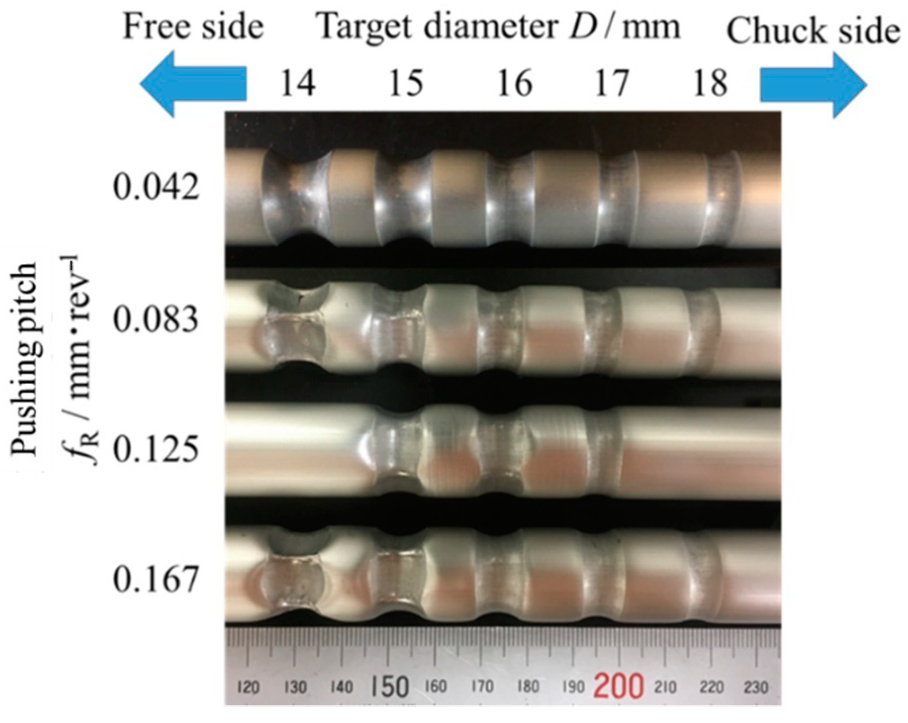
3.3.2. Effect of Pushing Pitch

Figure 15 shows the effect of pushing pitch on the appearance and formability with a steel ball diameter Φb = 15.9 mm. The cross-sectional states of the formed tubes are shown in Table 5. The results indicate that the tube was polygonalized with increasing pushing pitch. It is considered that as the pushing pitch increases, the contact area between the tube and the ball increases per rotation, and thus the tube perimeter did not shrink sufficiently and the surplus perimeter caused the polygonization force to disperse.

4. Conclusions

The following conclusions can be drawn from the present research:
1
A ball die, which can push the balls flexibly in the radial direction, was developed.
2
It was possible to reduce the tube diameter at the halfway point of an AA1050 tube whose diameter and thickness were 19 and 1 mm, respectively. The maximum diameter reduction ratio for forming the tube without any defects was 10.5% in the case of one-pass forming.
3
When processing with a large diameter reduction rate was performed, the cross-section deformed to a pentagonal shape. This defect was improved by two-pass forming.
4
A smooth formed surface was obtained under the condition of the appropriate feed pitch. If the feed pitch was too large, spiral marks appeared on the surface of the tube.
5
Elongation and twisting of the tube could be suppressed by increasing the feed pitch or feeding the ball die towards the chucked end.
6
The smaller diameter of the steel ball made it possible to process a larger diameter reduction ratio.
7
The maximum diameter reduction ratio got bigger with decreasing the pushing pitch of the steel balls.
8
When a steel ball was pressed into the tube, the wall thickness of the tube decreased with an increase in the pushing depth.

Author Contributions

Conceptualization, S.H., T.I., S.K. and T.K.; methodology, T.I., S.K. and T.K.; validation, S.H. and T.I.; investigation, S.H. and T.I. and T.K.; data curation, S.H. and T.I.; formal analysis, S.H. and T.I.; resources, T.K.; writing—original draft preparation, S.H. and T.I.; writing—review and editing, S.H., T.I., S.G., S.K. and T.K.; visualization, S.H. and T.I.; supervision, T.K.; project administration, S.H., T.I., S.G., S.K. and T.K.; funding acquisition, T.K. All authors have read and agreed to the published version of the manuscript.

Funding

This research received no external funding.

Conflicts of Interest

The authors declare no conflict of interest.

References

  1. Sato, M.; Mizumura, M.; Yoshida, T.; Kuriyama, Y.; Suzuki, K.; Tomizawa, A. Deformation type in forming of horn tubes—Fundamental research for forming of closed-section parts from sheet metal I. J. JSTP 2017, 59, 27–31. [Google Scholar] [CrossRef] [Green Version]
  2. Sato, M.; Mizumura, M.; Kuriyama, Y.; Suzuki, K.; Tomizawa, A. Deformation type in forming of curved conical tubes—Fundamental research for forming of closed-section parts from sheet metal II. J. JSTP 2018, 59, 229–233. [Google Scholar] [CrossRef]
  3. Sato, M.; Mizumura, M.; Kuriyama, Y.; Suzuki, K. Deformation paths of horn tube, curved circular tube and curved conical tube-Fundamental research for forming of closed-section parts from sheet metal III. J. JSTP 2020, 61, 131–135. [Google Scholar] [CrossRef]
  4. Wang, X.; Li, P.; Wang, R. Study on hydro-forming technology of manufacturing bimetallic CRA-lined pipe. Int. J. Mach. Tools Manuf. 2005, 45, 373–378. [Google Scholar] [CrossRef]
  5. Kumar, R.U.; Reddy, P.R.; Sitaramaraju, A.V. Role of Viscosity in Hydro-forming Process. Mater. Today Proc. 2017, 4, 790–798. [Google Scholar] [CrossRef]
  6. Cristino, V.; Magrinho, J.; Centeno, G.; Silva, M.; Martins, P.A.F. Theory of single point incremental forming of tubes. J. Mater. Process. Technol. 2020, 287, 116659. [Google Scholar] [CrossRef]
  7. Cui, X.; Mo, J.; Li, J.; Zhao, J.; Zhu, Y.; Huang, L.; Li, Z.; Zhong, K. Electromagnetic incremental forming (EMIF): A novel aluminum alloy sheet and tube forming technology. J. Mater. Process. Technol. 2014, 214, 409–427. [Google Scholar] [CrossRef]
  8. Becker, C.; Tekkaya, E.; Kleiner, M. Fundamentals of the incremental tube forming process. CIRP Ann. 2014, 63, 253–256. [Google Scholar] [CrossRef]
  9. Xu, W.; Wu, H.; Ma, H.; Shan, D. Damage evolution and ductile fracture prediction during tube spinning of titanium alloy. Int. J. Mech. Sci. 2018, 135, 226–239. [Google Scholar] [CrossRef]
  10. Wang, X.; Hu, Z.; Yuan, S.; Hua, L. Influence of tube spinning on formability of friction stir welded aluminum alloy tubes for hydroforming application. Mater. Sci. Eng. A 2014, 607, 245–252. [Google Scholar] [CrossRef]
  11. Ozer, A.; Sekiguchi, A.; Arai, H. Experimental implementation and analysis of robotic metal spinning with enhanced trajectory tracking algorithms. Robot. Comput. Integr. Manuf. 2012, 28, 539–550. [Google Scholar] [CrossRef]
  12. Murata, M.; Kuboki, T.; Murai, T. Compression spinning of circular magnesium tube using heated roller tool. J. Mater. Process. Technol. 2005, 163, 540–545. [Google Scholar] [CrossRef]
  13. Kuboki, T.; Takahashi, K.; Sanda, K.; Moriya, S.; Ishida, K. Development of a Tube-Spinning Machine for Thin Tubes with a Large Diameter. Mater. Trans. 2012, 53, 853–861. [Google Scholar] [CrossRef]
  14. Kanayama, K.; Yoshioka, K.; Shigematsu, I.; Hirai, Y. Effect of friction on the processing force in tube reducing of aluminum alloy by using planetary ball die. J. Jpn. Inst. Light Met. 1992, 42, 61–66. [Google Scholar] [CrossRef] [Green Version]
  15. Kanayama, K.; Yoshioka, K.; Shigematsu, I.; Kozuka, T. Tube reducing of welded titanium tube by using planetary ball die. J. Jpn. Inst. Light Met. 1992, 42, 657–662. [Google Scholar] [CrossRef]
  16. Guang-Liang, Z.; Shi-Hong, Z.; Bing, L.; Hai-Qu, Z. Analysis on folding defects of inner grooved copper tubes during ball spin forming. J. Mater. Process. Technol. 2007, 184, 393–400. [Google Scholar]
Figure 1. Schematics of ball die and deformed tube.
Metals 10 01627 g001
Figure 2. Schematic diagram of the experimental ball die.
Metals 10 01627 g002
Figure 3. Schematic diagram of scribe lines on the tube.
Metals 10 01627 g003
Figure 4. Appearance of the formed tubes (a-1) spiral mark: the diameter reduction ratio κD = 15%, n = 85 rpm, f = 3.0 mm/rev, (b-1) smooth surface: κD = 15 %, n = 85 rpm, f = 0.5 mm/rev. The photographs (a-2) and (b-2) are high magnification version of (a-1) and (b-1), respectively.
Metals 10 01627 g004
Figure 5. Pentagonal deformation.
Metals 10 01627 g005
Figure 6. Distribution of the outer diameter of the formed tubes.
Metals 10 01627 g006
Figure 7. Relationship between the feed pitch and twist angle.
Metals 10 01627 g007
Figure 8. Cross-section of the tube (a) κD = 10.5 %, n = 85 rpm, f = 1.5 mm/rev, feed direction: chuck to free side (b) κD = 10.5 %, n = 85 rpm, f = 1.5 mm/rev, feed direction: free side to chuck.
Metals 10 01627 g008
Figure 9. Schematic diagram of cam-implemented ball die.
Metals 10 01627 g009
Figure 10. Overall view of the experimental equipment.
Metals 10 01627 g010
Figure 11. Schematic diagram of the experimental machine.
Metals 10 01627 g011
Figure 12. Schematic diagram of processing.
Metals 10 01627 g012
Figure 13. Appearance of formed tube when fR = 0.042 mm/rev.
Metals 10 01627 g013
Figure 14. Cross-section of the tube (ball diameter Φb = 15.9 mm, pushing pitch fR = 0.042 mm/rev).
Metals 10 01627 g014
Figure 15. Appearance of formed tube when Φb = 15.9 mm.
Metals 10 01627 g015
Table 1. Conditions of the experiment.
TubeOuter diameter Dp/[mm]19.0
Thickness t/[mm]0.9
Experimental conditionsDiameter reduction ratio κD/[%]5.310.515.8
Target diameter DT/[mm]181716
Rotational speed n/[rpm]50, 85, 140
Feed pitch f/[mm/rev]0.5, 1.0, 1.5, 2.0, 2.5, 3.0
Formed length l/[mm]50, 120
Table 2. Conditions of experiment.
Tube diameter D0/mm19
Wall thickness t0/mm1.0
Ball diameter Φb/mm15.9, 19.1, 25.4
Pushing pitch fR/mm·rev−10.042, 0.083, 0.125, 0.167
Pushing depth δ/mm0.51.01.52.02.53.03.5
Target diameter D/mm18171615141312
Diameter reduction ratio κ/%5.310.515.821.126.331.636.8
Table 3. Cross-section of formed tube when fR = 0.042 mm/rev.
Metals 10 01627 i001
Table 4. The thickness increasing ratio η.
D/mmη/%
180.0
171.1
16−6.4
15−20.4
14−44.7
13−40.2
Table 5. Cross-sectional state of the formed tubes.
Ball Diameter
Φb = 15.9 mm
Target Diameter D/mm
Pushing Pitch
fR/mm·rev−1
1415161718
0.042
0.083××
0.125×××
0.167××
Publisher’s Note: MDPI stays neutral with regard to jurisdictional claims in published maps and institutional affiliations.

