Computer-Aided Engineering Environment for Designing Tailored Forming Components


Abstract
1. Introduction
2. Research Background
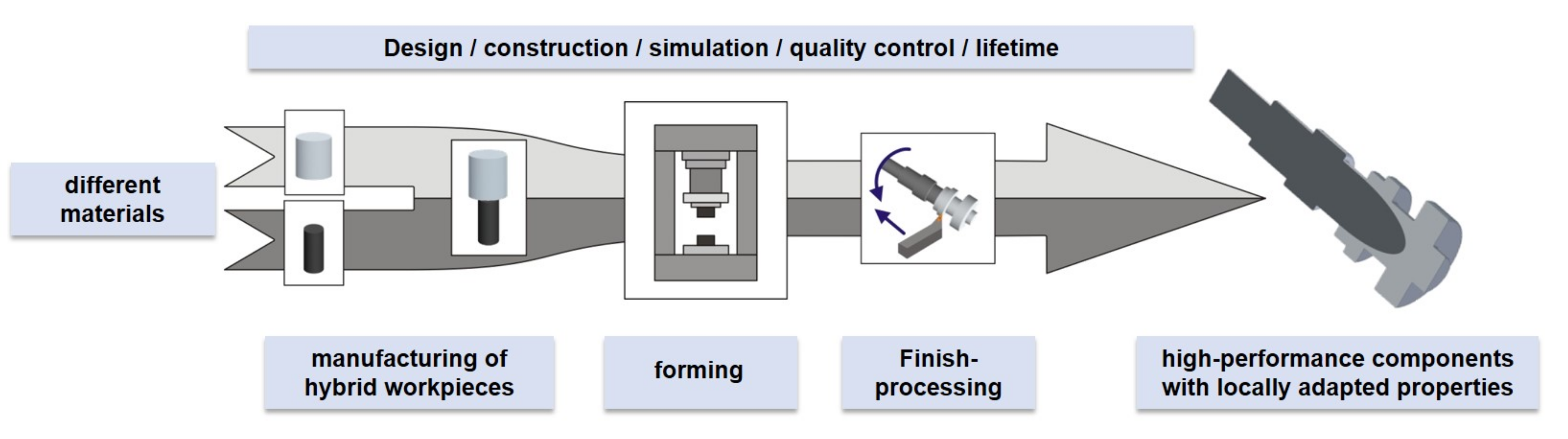
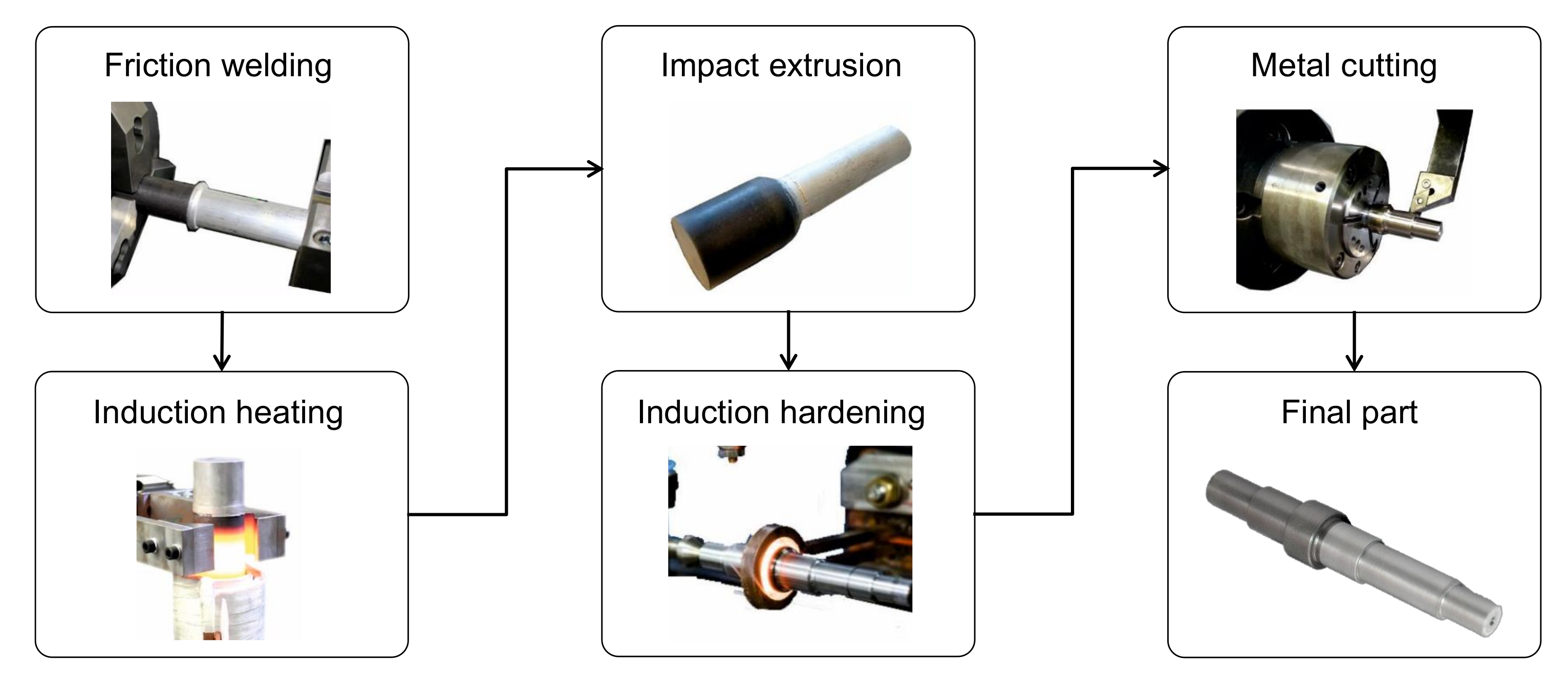
2.1. Manufacturing Processes for Multi-Material Parts
2.2. Computer-Aided Engineering Environments
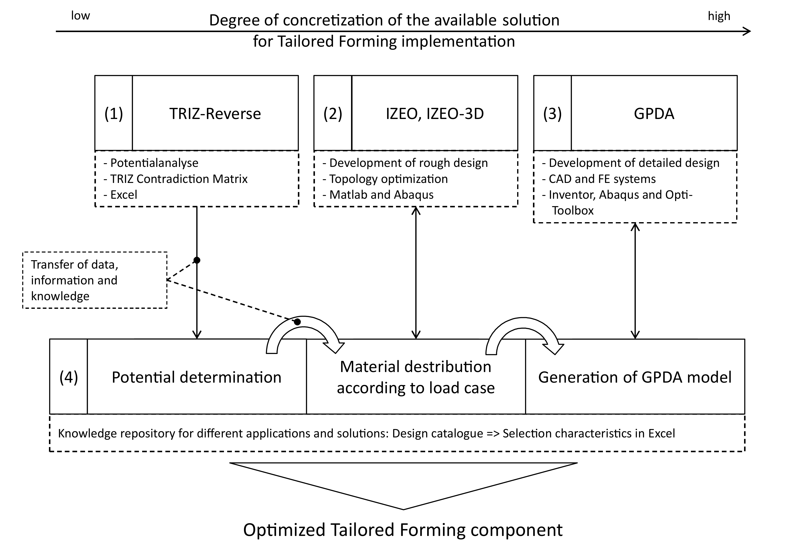
3. Computer-Aided Engineering Environment for Tailored Forming Parts
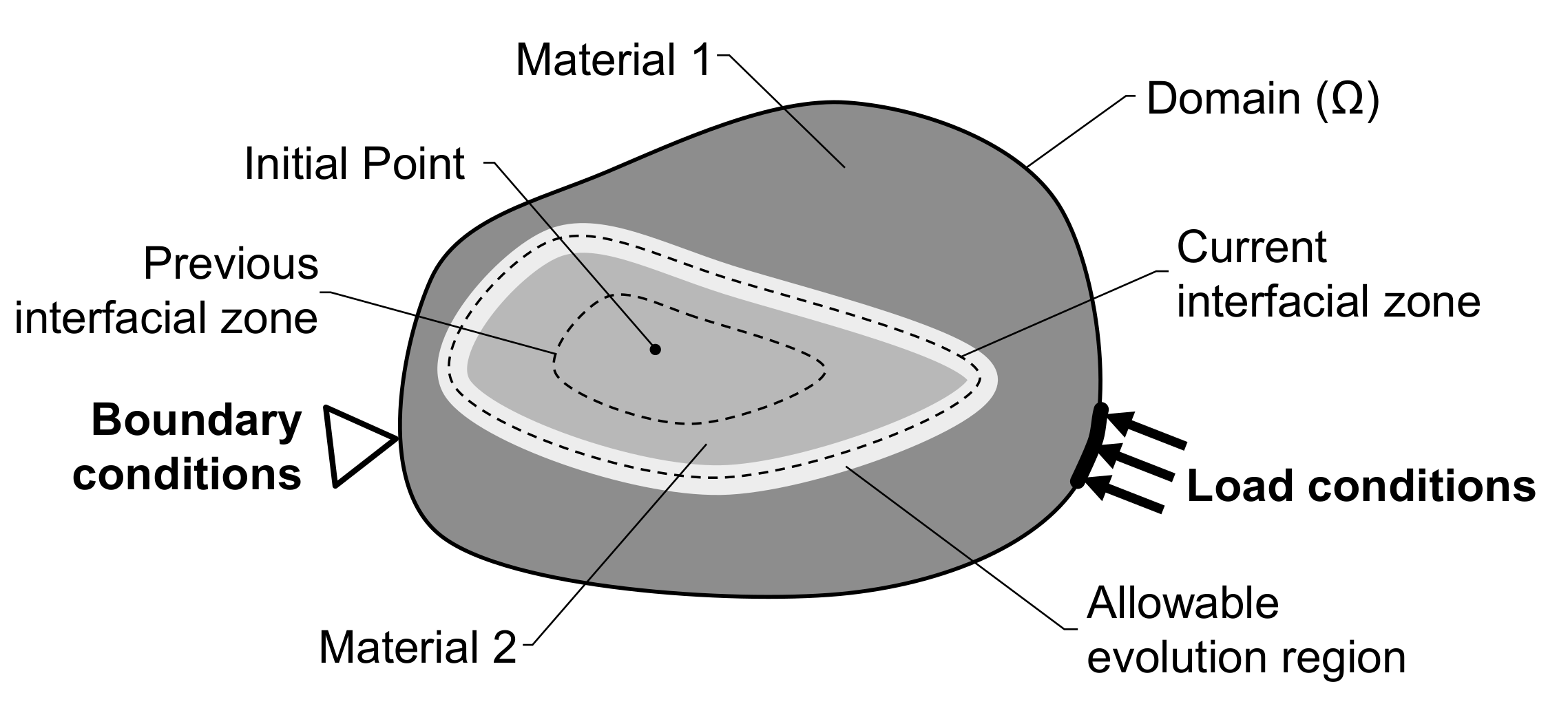
3.1. Rough Design by Interfacial Zone Evolutionary Optimization
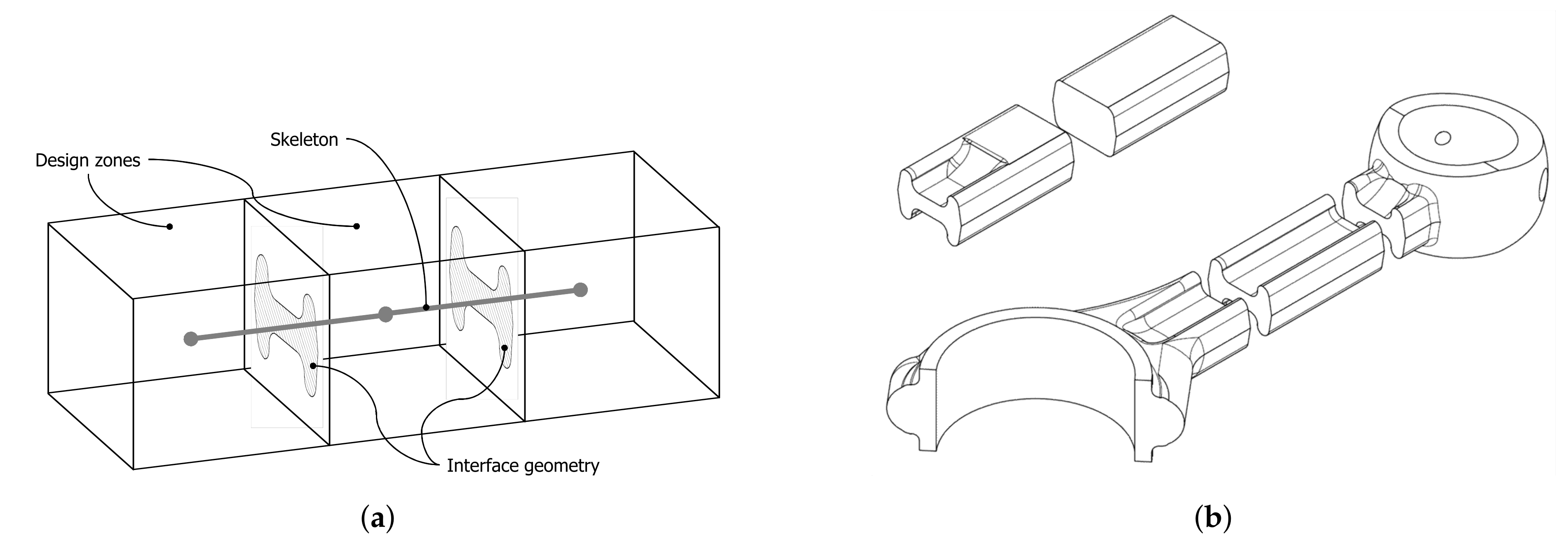
3.2. Detailed Design Using the Generative Parametric Design Approach
4. Implementation for Shaft-Like Tailored Forming Parts
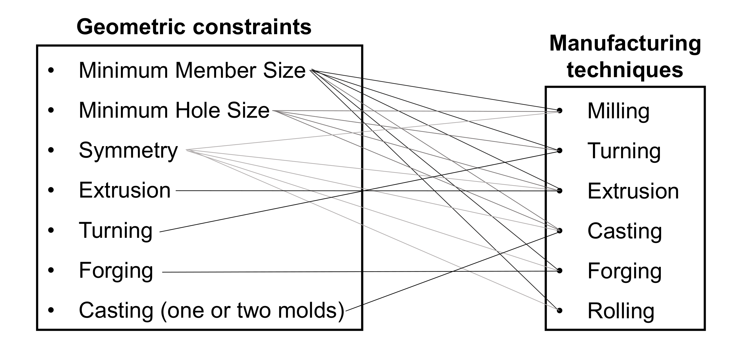
4.1. Expansion of Geometric Constraints
4.2. IZEO and Robust Design for Tailored Forming
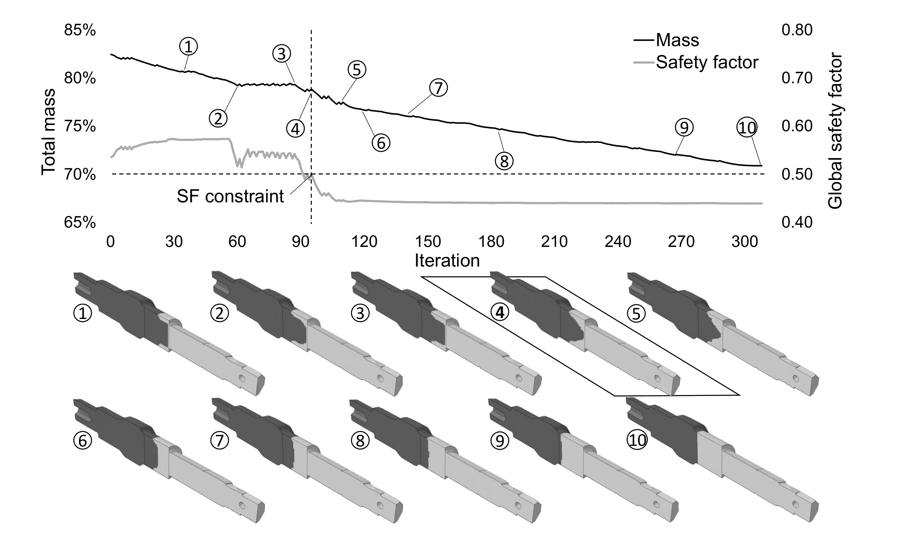
4.3. Intermediate Results
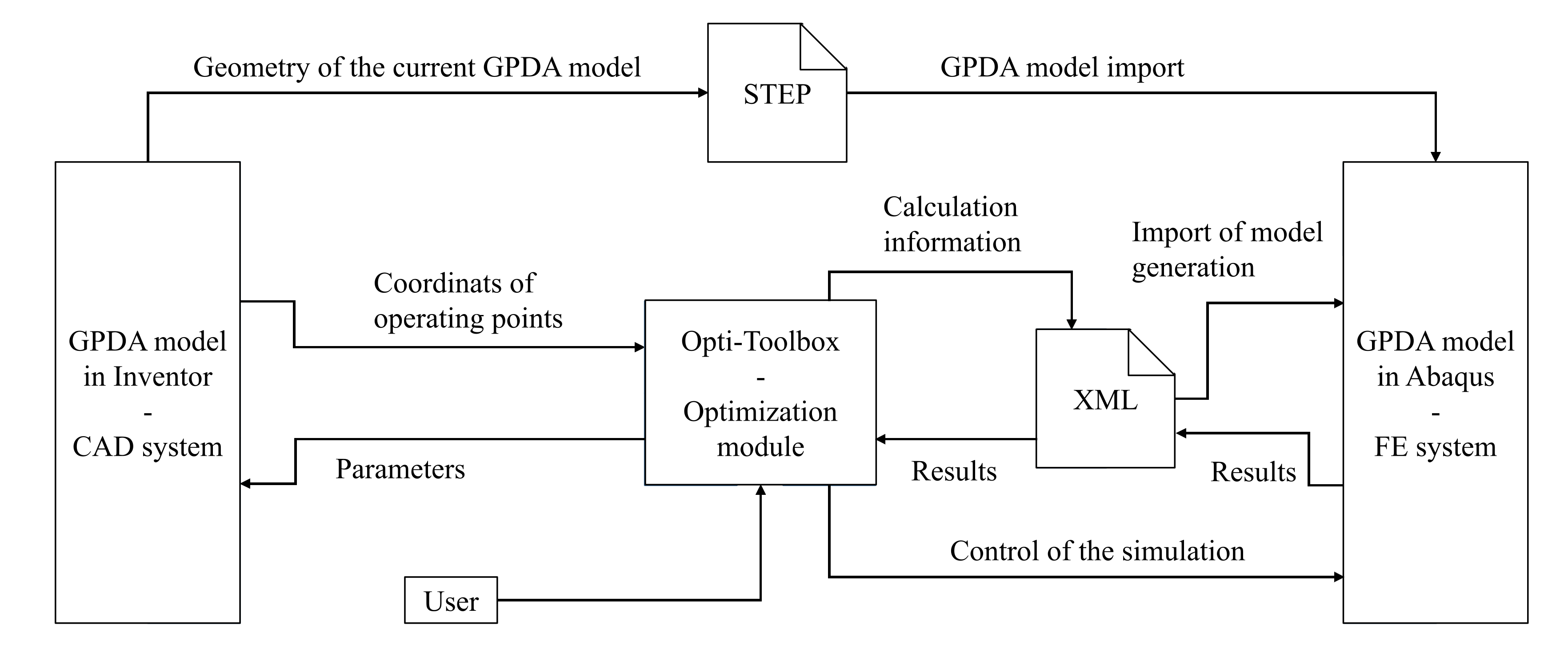
4.4. GPDA for Tailored Forming
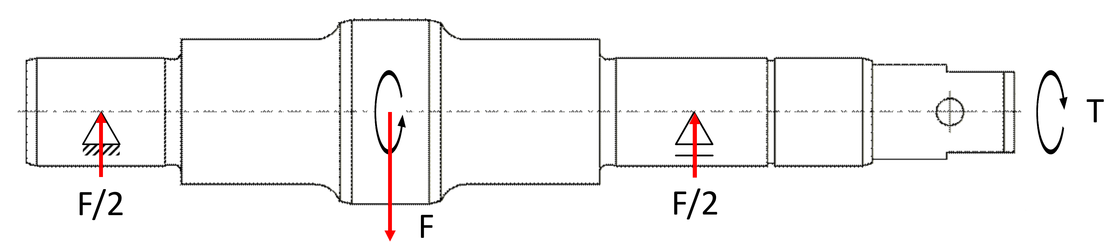
4.5. Application Example of the GPDA: Model Adaptation in Case of Changes in Boundary Conditions
5. Discussion
6. Summary and Outlook
Author Contributions
Funding
Acknowledgments
Conflicts of Interest
Abbreviations
| BESO | Bidirectional Evolutionary Structure Optimization |
| CAD | Computer-aided Design |
| CAEE | Computer-aided Engineering Environment |
| CBR | Case-based Reasoning |
| CPM | Characteristics-Properties Modeling |
| CRC | Collaborative Research Center |
| DfX | Design for X |
| GPDA | Generative Parametric Design Approach |
| IZEO | Interfacial Zone Evolutionary Optimization |
| KBE | Knowledge-based Engineering |
| LACE | Lateral Angular Co-Extrusion |
| PDD | Property-Driven Development |
References
- Behrens, B.A.; Chugreev, A.; Matthias, T.; Poll, G.; Pape, F.; Coors, T.; Hassel, T.; Maier, H.; Mildebrath, M. Manufacturing and Evaluation of Multi-Material Axial-Bearing Washers by Tailored Forming. Metals 2019, 9, 232. [Google Scholar]
- Behrens, B.A.; Bouguecha, A.; Frischkorn, C.; Huskic, A.; Stakhieva, A.; Duran, D. Tailored Forming Technology for Three Dimensional Components: Approaches to Heating and Forming. In Proceedings of the 5th International Conference on Thermomechanical Processing, Milan, Italy, 6–28 October 2016. [Google Scholar]
- Denkena, B.; Bergmann, B.; Witt, M. Automatic process parameter adaption for a hybrid workpieceduring cylindrical operations. Int. J. Adv. Manuf. Technol. 2017, 95, 311–316. [Google Scholar]
- Ashby, M.; Cebon, D. Materials selection in mechanical design. J. Phys. IV 1993, 3, 1–9. [Google Scholar]
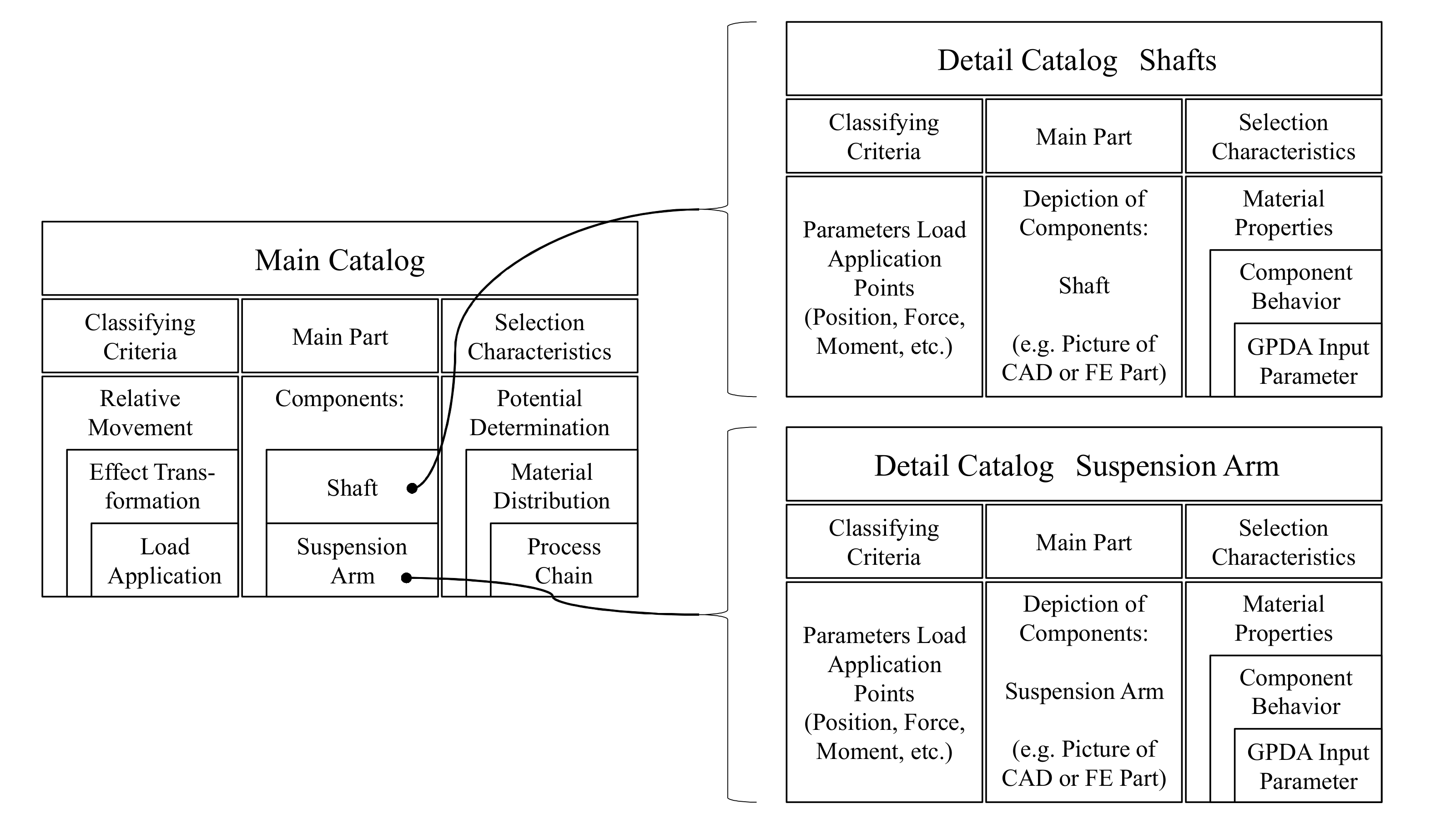
- Brockmöller, T.; Gembarski, P.; Mozgova, I.; Lachmayer, R. Design Catalogue in a CAE Environment for the Illustration of Tailored Forming. In Proceedings of the 59th Ilmenau Scientific Colloquium, Technische Universität, Ilmenau, Ilmenau, Germany, 11–15 September 2017. [Google Scholar]
- Siqueira, R. Design and Optimization Method for Manufacturable Multi-material Components. Ph. D Thesis, Leibniz Universität Hannover, Hannover, Germany, 2019. [Google Scholar]
- Cutkosky, M.; Sangbae, K. Design and fabrication of multi-material structures for bioinspired robots. Philos. Trans. R. Soc. Lond. Ser. A 2009, 367, 1799–1813. [Google Scholar]
- Altach, J.; Bader, B.; Fröhlich, T.; Klaiber, D.; Vietor, T. Approach to the systematic categorization and qualitative evaluation of multi-material designs for use in vehicle body structures. Procedia CIRP 2019, 84, 908–915. [Google Scholar]
- Kleemann, S.; Fröhlich, T.; Türck, E.; Vietor, T. A methodological approach towards multi-material design of automotive components. Procedia CIRP 2017, 60, 68–73. [Google Scholar]
- Gouker, R.; Gupta, S.; Bruck, H.; Holzschuh, T. Manufacturing of multi-material compliant mechanisms using multi-material molding. Int. J. Adv. Manuf. Technol. 2006, 30, 1049–1075. [Google Scholar]
- Behrens, B.A.; Breidenstein, B.; Duran, D.; Herbst, S.; Lachmayer, R.; Löhnert, S.; Matthias, T.; Mozgova, I.; Nürnberger, F.; Prasanthan, V.; et al. Simulation-Aided Process Chain Design for the Manufacturing of Hybrid Shafts. J. Heat Treatm. Mater. 2019, 74, 115–135. [Google Scholar]
- Suh, N. Complexity: Theory and Applications; Oxford University Press: New York, NY, USA, 2005. [Google Scholar]
- Gembarski, P.; Lachmayer, R. Complexity Management of Solution Spaces in Mass Customization. In Proceedings of the 8th International Conference on Mass Customization and Personalization-Community of Europe (MCP-CE 2018), Novi Sad, Serbia, 19–21 September 2018; pp. 123–131. [Google Scholar]
- Gembarski, P.; Lachmayer, R. Solution space development: Conceptual reflections and development of the parameter space matrix as planning tool for geometry-based solution spaces. Int. J. Ind. Eng. Manag. 2018, 3, 4. [Google Scholar]
- Vajna, S.; Weber, C.; Zeman, K.; Hehenberger, P.; Gerhard, D.; Wartzack, S. CAx für Ingenieure—Eine Praxisbezogenen Einführung, 3rd ed.; Springer: Berlin, Germany, 2018. [Google Scholar]
- Huang, G.Q. Design for X: Concurrent Engineering Imperatives; Springer Science+Business Media: Dordrecht, The Netherlands, 1996. [Google Scholar]
- Boothroyd, G. Product design for manufacture and assembly. Comput. Aided Des. 1994, 26, 505–520. [Google Scholar]
- Behrens, B.A.; Goldstein, R.; Guisbert, D.; Duran, D. Thermomechanical Processing of Friction Welded Steel-Aluminum Billets to Improve Joining Zone Properties. In Proceedings of the 4th International Conference on Heat Treatment and Surface Engineering in Automotive Applications (Thermal Processing in Motion), Spartanburg, SC, USA, 5–7 June 2018. [Google Scholar]
- Denkena, B.; Bergmann, B.; Breidenstein, B.; Prasanthan, V.; Witt, M. Analysis of potentials to improve the machining of hybrid workpieces. Prod. Eng. 2018, 13, 11–19. [Google Scholar] [CrossRef]
- Gembarski, P.C. Komplexitätsmanagement mittels wissensbasiertem CAD—Ein Ansatz zum unternehmenstypologischen Management konstruktiver Lösungsräume. Ph.D. Thesis, Leibniz Universität Hannover, Hannover, Germany, 2018. [Google Scholar]
- Biedermann, M.; Meboldt, M. Computational design synthesis of additive manufactured multi-flow nozzles. Addit. Manuf. 2020, 35, 1–9. [Google Scholar] [CrossRef]
- Li, H. Generative Design Approach for Robust Solution Development. Ph.D. Thesis, Leibniz Universität Hannover, Hannover, Germany, 2020. [Google Scholar]
- Stokes, M. Managing Engineering Knowledge - MOKA: Methodology for Knowledge Based Engineering Applications; Professional Engineering Publishing Limited: London, UK, 2001. [Google Scholar]
- Kulon, J.; Broomhead, P.; Mynors, D. Applying knowledge-based engineering to traditional manufacturing design. Int. J. Adv. Manuf. Technol. 2006, 30, 945–951. [Google Scholar] [CrossRef]
- Hopgood, A.A. Intelligent Systems for Engineers and Scientists; CRC Press: Boca Raton, FL, USA, 2016. [Google Scholar]
- Koch, S.; Behrens, B.A.; Hübner, S.; Scheffler, R.; Wrobel, G.; Peßow, M.; Bauer, D. 3D CAD modeling of deep drawing tools based on a new graphical language. Comput. Aided Des. Appl. 2018, 15, 619–630. [Google Scholar] [CrossRef]
- Gembarski, P.C. On the Conception of a Multi-agent Analysis and Optimization Tool for Mechanical Engineering Parts. In Agents and Multi-Agent Systems: Technologies and Applications 2020; Springer: Berlin/Heidelberg, Germany, 2020; pp. 93–102. [Google Scholar]
- Kim, H.; Altan, T.; Sevenler, K. Computer-aided part and processing-sequence design in cold forging. J. Mater. Process. Technol. 1992, 33, 57–74. [Google Scholar] [CrossRef]
- Caporalli, Â.; Gileno, L.; Button, S. Expert system for hot forging design. J. Mater. Process. Technol. 1998, 80–81, 131–135. [Google Scholar] [CrossRef]
- Boyle, I.; Rong, Y.; Brown, D.C. A review and analysis of current computer-aided fixture design approaches. Rob. Comput. Integr. Manuf. 2011, 27, 1–12. [Google Scholar] [CrossRef]
- Findik, F. Recent developments in explosive welding. Mater. Des. 2010, 32, 1081–1093. [Google Scholar] [CrossRef]
- Han, J.; Ahn, J.; Shin, M. Effect of interlayer thickness on shear deformation behavior of AA5083 aluminum alloy/SS41 steel plates manufactured by explosive welding. J. Mater. Sci. 2003, 38, 13–18. [Google Scholar] [CrossRef]
- Hirtler, M.; Jedynak, A.; Sydow, B.; Sviridov, A.; Bambach, M. A Study on the Mechanical Properties of Hybrid Parts Manufactured by Forging and Wire Arc Additive Manufacturing. Procedia Manuf. 2020, 47, 1141–1148. [Google Scholar] [CrossRef]
- Vaezi, M.; Chianrabutra, S.; Mellor, B.; Yang, S. Multiple material additive manufacturing-Part 1: A review. Virtual Phys. Prototyp. 2013, 8, 19–50. [Google Scholar] [CrossRef]
- Leiber, R. Hybridschmieden bringt den Leichtbau voran. Alum. Prax. 2011, 7, 7–8. [Google Scholar]
- Kriwall, M.; Stonis, M.; Bick, T.; Treutler, K.; Wesling, V. Dependence of the Joint Strength on Different Forming Steps and Geometry in Hybrid Compound Forging of Bulk Aluminum Parts and Steel Sheets. Procedia Manuf. 2020, 47, 356–361. [Google Scholar] [CrossRef]
- Behrens, B.A.; Chugreev, A.; Selinski, M.; Matthias, T. Joining zone shape optimisation for hybrid components made of aluminium-steel by geometrically adapted joining surfaces in the friction welding process. AIP Conf. Proc. 2019, 2113, 040027. [Google Scholar]
- Maalekian, M. Friction welding - critical assessment of literature. Sci. Technol. Weld. Join. 2007, 12, 738–759. [Google Scholar] [CrossRef]
- Nothdurft, S.; Springer, A.; Kaierle, S.; Ohrdes, H.; Twiefel, J.; Wallaschek, J.; Mildebrath, M.; Maier, H.; Hassel, T.; Overmeyer, L. Laser welding of dissimilar low-alloyed steel-steel butt joints and the effects of beam position and ultrasound excitation on the microstructure. J. Laser Appl. 2018, 30, 032417. [Google Scholar] [CrossRef]
- Chugreeva, A.; Mildebarth, M.; Diefenbach, J.; Barroi, A.; Lammers, M.; Hermsdorf, J.; Hassel, T.; Overmeyer, L.; Behrens, B.A. Manufacturing of High-Performance Bi-Metal Bevel Gears by Combined Deposition Welding and Forging. Metals 2018, 8, 898. [Google Scholar] [CrossRef]
- Behrens, B.A.; Klose, C.; Chugreev, A.; Heimes, N.; Thürer, S.; Uhe, J. A Numerical Study on Co-Extrusion to Produce Coaxial Aluminum-Steel Compounds with Longitudinal Weld Seams. Metals 2018, 8, 717. [Google Scholar] [CrossRef]
- Kruse, J.; Jagodinski, A.; Langner, J.; Stonis, M.; Behrens, B.A. Investigation of the joining zone displacement of cross-wedge rolled serially arranged hybrid parts. Int. J. Mater. Form. 2019, 1–13. [Google Scholar] [CrossRef]
- Behrens, B.A.; Bonhage, M.; Bohr, D.; Duran, D. Simulation Assisted Process Development for Tailored Forming. Mater. Sci. Forum 2019, 949, 101–111. [Google Scholar] [CrossRef]
- Herbst, S.; Maier, H.; Nürnberger, F. Strategies for the Heat Treatment of Steel-Aluminium Hybrid Components. J. Heat Treatm. Mater. 2018, 73, 268–282. [Google Scholar] [CrossRef]
- Behrens, B.A.; Chugreev, A.; Matthias, T.; Nothdurft, S.; Hermsdorf, J.; Kaierle, S.; Ohrdes, H.; Twiefel, J.; Wallaschek, J.; Mildebrath, M.; et al. Investigation of the composite strength of hybrid steel-steel semi-finished products manufactured by laser beam welding and friction welding. IOP Conf. Ser. Mater. Sci. Eng. 2018, 461, 012049. [Google Scholar] [CrossRef]
- Behrens, B.A.; Bouguecha, A.; Vucetic, M.; Peshekhodov, I.; Matthias, T.; Kolbasnikov, N.; Sokolov, S.; Ganin, S. Experimental investigations on the state of the friction-welded joint zone in steel hybrid components after process-relevant thermomechanical loadings. AIP Conf. Proc. 2016, 1769, 130013. [Google Scholar]
- Behrens, B.A.; Chugreev, A.; Matthias, T. Characterisation of the joining zone of serially arranged hybrid semi-finished components. AIP Conf. Proc. 2018, 1960, 040002. [Google Scholar]
- Goldstein, R.; Behrens, B.A. Role of Thermal Processing in Tailored Forming Technology for Manufacturing Multi-Material Components. In Proceedings of the 29th ASM Heat Treating Society Conference, Columbus, OH, USA, 24–26 October 2017. [Google Scholar]
- Behrens, B.A.; Bouguecha, A.; Frischkorn, C.; Chugreeva, A.; Duran, D. Angepasste Erwärmungs- und Umformverfahren für hybride Massivbauteile 2016. In Proceedings of the 23th Sächsische Fachtagung Umformtechnik (SFU), Dresden, Germany, 7–8 December 2016; pp. 184–193. [Google Scholar]
- Behrens, B.A.; Amiri, A.; Duran, D.; Nothdurft, S.; Hermsdorf, J.S.; Kaierle, S.; Ohrdes, H.; Wallaschek, J.; Hassel, T. Improving the mechanical properties of laser beam welded hybrid workpieces by deformation processing. AIP Conf. Proc. 2019, 2113, 040025. [Google Scholar]
- Denkena, B.; Breidenstein, B.; Prasanthan, V. Influence of Tool Properties on the Thermomechanical Load during Turning of Hybrid Components and the Resulting Surface Properties. J. Heat Treatm. Mat. 2018, 73, 223–231. [Google Scholar] [CrossRef]
- Breidenstein, B.; Denkena, B.; Meyer, K.; Prasanthan, V. Influence of subsurface properties on the application behavior of hybrid components. Procedia CIRP 2020, 87, 302–308. [Google Scholar] [CrossRef]
- Lindemann, U. Methodische Entwicklung Technischer Produkte: Methoden Flexibel und Situationsgerecht Anwenden; Springer: Berlin/Heidelberg, Germany, 2009. [Google Scholar]
- Pahl, G.; Beitz, W.; Feldhusen, J.; Grote, K. Engineering Design: A Systematic Approach; Springer: London, UK, 2007. [Google Scholar]
- Chandrasegaran, S.; Ramani, K.; Sriram, R.; Horváth, I.; Bernard, A.; Harik, R.; Gao, W. The evolution, challenges, and future of knowledge representation in product design systems. Comput. Aided Des. 2013, 45, 204–228. [Google Scholar] [CrossRef]
- Vajna, S.; Weber, C.; Bley, H.; Zeman, K. Integrated Design Engineering; Springer-Verlag: Berlin/Heidelberg, Germany, 2014. [Google Scholar]
- Juan, Y.C.; Ou-Yang, C.; Lin, J.S. A process-oriented multi-agent system development approach to support the cooperation-activities of concurrent new product development. Comput. Ind. Eng. 2009, 57, 1363–1376. [Google Scholar] [CrossRef]
- Stroud, I.; Nagy, H. Solid Modelling and CAD Systems: How to Survive a CAD System; Springer Science & Business Media: Berlin/Heidelberg, Germany, 2011. [Google Scholar]
- Riesenfeld, R.; Haimes, R.; Cohen, E. Initiating a CAD renaissance: Multidisciplinary analysis driven design: Framework for a new generation of advanced computational design, engineering and manufacturing environments. Comput. Methods Appl. Mech. Eng. 2015, 284, 1054–1072. [Google Scholar] [CrossRef]
- Shah, J. Designing with parametric cad: Classification and comparison of construction techniques Geometric Modelling. In Proceedings of the International Workshop on Geometric Modelling; Springer: Berlin/Heidelberg, Germany, 2001; pp. 53–68. [Google Scholar]
- Weber, C. Looking at DFX and Product Maturity from the Perspective of a New Approach to Modelling Product and Product Development Processes. In The Future of Product Development; Krause, F.L., Ed.; Springer: Berlin/Heidelberg, Germany, 2007; pp. 85–104. [Google Scholar]
- Verhagen, W.; Bermell-Garcia, P.; van Dijk, R.; Curran, R. A critical review of Knowledge-Based Engineering: An identification of research challenges. Adv. Eng. Inf. 2012, 26, 5–15. [Google Scholar] [CrossRef]
- LaRocca, G. Knowledge based Engineering: Between AI and CAD. Review of a Language based Technology to Support Engineering Design. Adv. Eng. Inf. 2012, 26, 159–179. [Google Scholar]
- Milton, N. Knowledge Technologies; Polimetrica S.a.s.: Monza, Italy, 2008; Volume 3. [Google Scholar]
- Gembarski, P.C.; Li, H.; Lachmayer, R. Template-based modelling of structural components. Int. J. Mech. Eng. Robot. Res. 2017, 6, 336–342. [Google Scholar] [CrossRef]
- Plappert, S.; Hoppe, L.; Gembarski, P.; Lachmayer, R. Application of Knowledge-Based Engineering for Teaching Design Knowledge to Design Students. In Proceedings of the Design Society: DESIGN Conference; Cambridge University Press: Cambridge, UK, 2020; Volume 1, pp. 1795–1804. [Google Scholar]
- Hirz, M.; Dietrich, W.; Gfrerrer, A.; Lang, J. Integrated Computer-Aided Design in Automotive Development, 1st ed.; Springer: Berlin/ Heidelberg, Germany, 2013. [Google Scholar]
- Skarka, W. Application of MOKA methodology in generative model creation using CATIA. Eng. Appl. Artif. Intell. 2007, 20, 677–690. [Google Scholar] [CrossRef]
- Wang, H.; Rong, Y. Case based reasoning method for computer aided welding fixture design. Comput. Aided Des. 2008, 40, 1121–1132. [Google Scholar] [CrossRef]
- Alacrón, R.; Chueco, J.; Garcia, J.; Idoipe, A. Fixture knowledge model development and implementation based on a functional design approach. Rob. Comput. Integr. Manuf. 2010, 26, 56–66. [Google Scholar]
- LaRocca, G.; van Tooren, M. Knowledge-based engineering to support aircraft multidisciplinary design and optimization. Proc. Inst. Mech. Eng. Part G J. Aerosp. Eng. 2010, 224, 1041–1055. [Google Scholar] [CrossRef]
- Roach, G.M.; Cox, J.J. A Case Study of the Product Design Generator. In Product Platform and Product Family Design; Springer: New York, NY, USA, 2006; pp. 499–512. [Google Scholar]
- Andrae, R.; Köhler, P. Simulation-oriented Transformation of CAD Models. Comput. Aided Des. Appl. 2016, 13, 340–347. [Google Scholar] [CrossRef][Green Version]
- Hvam, L.; Mortensen, N.H.; Riis, J. Product Customization; Springer Science & Business Media: Berlin/Heidelberg, Germany, 2008. [Google Scholar]
- Sauthoff, B. Generative parametrische Modellierung von Strukturkomponenten für die Technische Vererbung. Ph.D. Thesis, Leibniz Universität Hannover, Hannover, Germany, 2017. [Google Scholar]
- Cuillière, J.C.; François, V.; Nana, A. Automatic construction of structural CAD models from 3D topology optimization. Comput. Aided Des. Appl. 2018, 15, 107–121. [Google Scholar] [CrossRef]
- Brockmöller, T.; Mozgova, I.; Lachmayer, R. An Approach to analyse the Potential of Tailored Forming by TRIZ-Reverse. In 21st International Conference on Engineering Design; University of British Columbia: Vancouver, BC, Canada, 2017. [Google Scholar]
- Siqueira, R.; Mozgova, I.; Lachmayer, R. Development of a Topology Optimization Method for Tailored Forming Multi-Material Design. In Proceedings of the 24th ABCM International Congress of Mechanical Engineering, Curitiba, Brasil, 3–8 December 2017. [Google Scholar]
- Vatanabe, S.; Lippi, T.; de Lima, C.; Paulino, G.; Silva, E. Topology optimization with manufacturing constraints: A unified projection-based approach. Adv. Eng. Softw. 2016, 100, 97–112. [Google Scholar] [CrossRef]
- Yang, X.; Xie, Y.; Steven, G.; Querin, O. Bidirectional Evolutionary Method for Stiffness Optimization. AIAA J. 1999, 37, 1483–1488. [Google Scholar] [CrossRef]
- Siqueira, R.; Mozgova, I.; Lachmayer, R. An Interfacial Zone Evolutionary Optimization Method with Manufacturing Constraints for Hybrid Components. J. Comput. Des. Eng. 2018, 6, 387–397. [Google Scholar]
- Sauthoff, B.; Lachmayer, R. Generative Design Approach for Modelling of Large Design Spaces. In Proceedings of the 7th World Conference on Mass Customization, Personalization and Co-Creation (MCPC 2014); Brunoe, T., Nielsen, K., Joergensen, K., Taps, S., Eds.; Springer: Berlin/Heidelberg, Germany; New York, NY, USA; Dordrecht, The Netherlands; London, UK, 2014; pp. 241–251. [Google Scholar]
- Li, H.; Brockmöller, T.; Gembarski, P.; Lachmayer, R. An Investigation of a Generative Parametric Design Approach for a Robust Solution Development. In Proceedings of the Design Society: DESIGN Conference; Cambridge University Press: Cambridge, UK, 2020; Volume 1, pp. 315–324. [Google Scholar]
- Brockmöller, T.; Siqueira, R.; Mozgova, I.; Lachmayer, R. Rechnergestützte Entwicklungsumgebung zur Konstruktion von Tailored-Forming-Bauteilen. In DS 98: Proceedings of the 30th Symposium Design for X (DFX 2019); Krause, D., Paetzold, K., Wartzack, S., Eds.; TuTech Verlag: Hamburg, Germany, 2019; pp. 195–206. [Google Scholar]
- Gembarski, P.C.; Sauthoff, B.; Brockmöller, T.; Lachmayer, R. Operationalization of Manufacturing Restrictions for CAD and KBE-Systems. In Proceedings of the DESIGN 2016, 14th International Design Conference; Marjanović, D., Ed.; Tools, Practice & Innovation; The Design Society: Glasgow, UK, 2016; Volume 2, pp. 621–630. [Google Scholar]
- Roth, K. Design catalogues and their usage. In Engineering Design Synthesis; Chakrabarti, A., Ed.; Springer: London, UK, 2002. [Google Scholar]
- Franke, H.J.; Löffler, S.; Deimel, M. Increasing the Efficiency of Design Catalogues by Using Modern Data Processing Technologies. In Proceedings of the DS 32: Proceedings of the DESIGN 2004, 8th International Design Conference, Dubrovnik, Croatia, 18–21 May 2004. [Google Scholar]
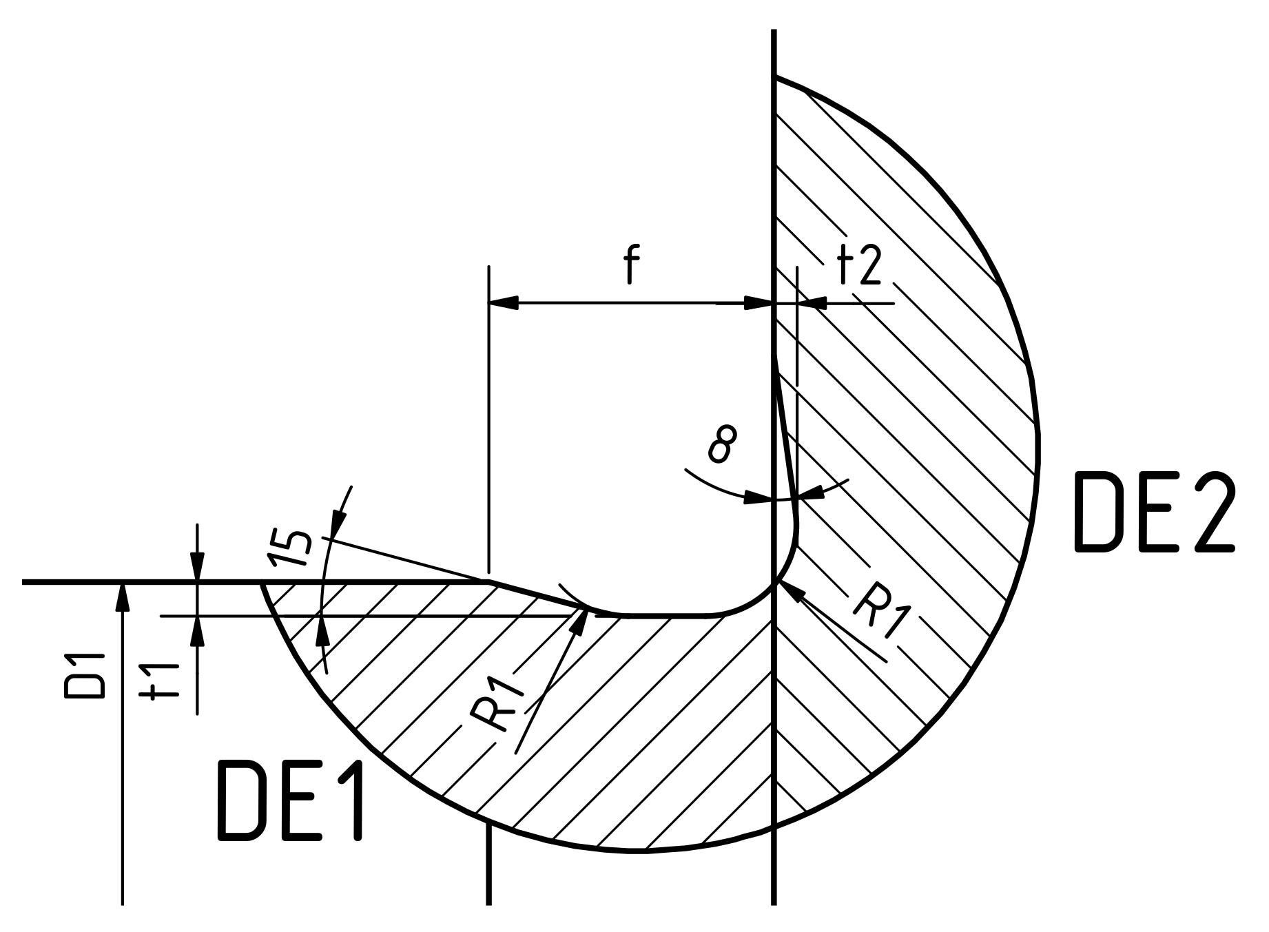
- DIN509:2006-12. Technical Drawings—Relief Grooves—Types and Dimensions—Tolerances; Beuth: Berlin, Germany, 2006. [Google Scholar]
- Töller, F.; Löhnert, S.; Wriggers, P. Bulk material models in Cohesive Zone Elements for simulation of joining zones. Finite Elem. Anal. Des. 2019, 164, 42–54. [Google Scholar] [CrossRef]


| Geometric Constraint | Definition | Control Parameters | Representation |
|---|---|---|---|
| Minimum member size | Level of detail in the manufacturing process | Minimum size |  |
| Uni/Bidirectional growth | Unidirectional access of the manufacturing tools or serial connection of materials | Vector of growth direction |  |
| Extrusion | Extrusion direction in the manufacturing | Vector of extrusion direction |  |
| Planar symmetry | Symmetry imposed by the processes | Point and normal vector to the plane |  |
| Material | Density | Yield Stress | Ultimate Stress |
|---|---|---|---|
| Steel (41Cr4) | 7.85 | 660 MPa | 1020 MPa |
| Aluminum (EN AW-6082) | 2.70 | 280 MPa | 385 MPa |
| R1 | f | t1 | t2 | D1 |
|---|---|---|---|---|
| 2 | >3 | |||
| >18 | ||||
| 4 | >80 |
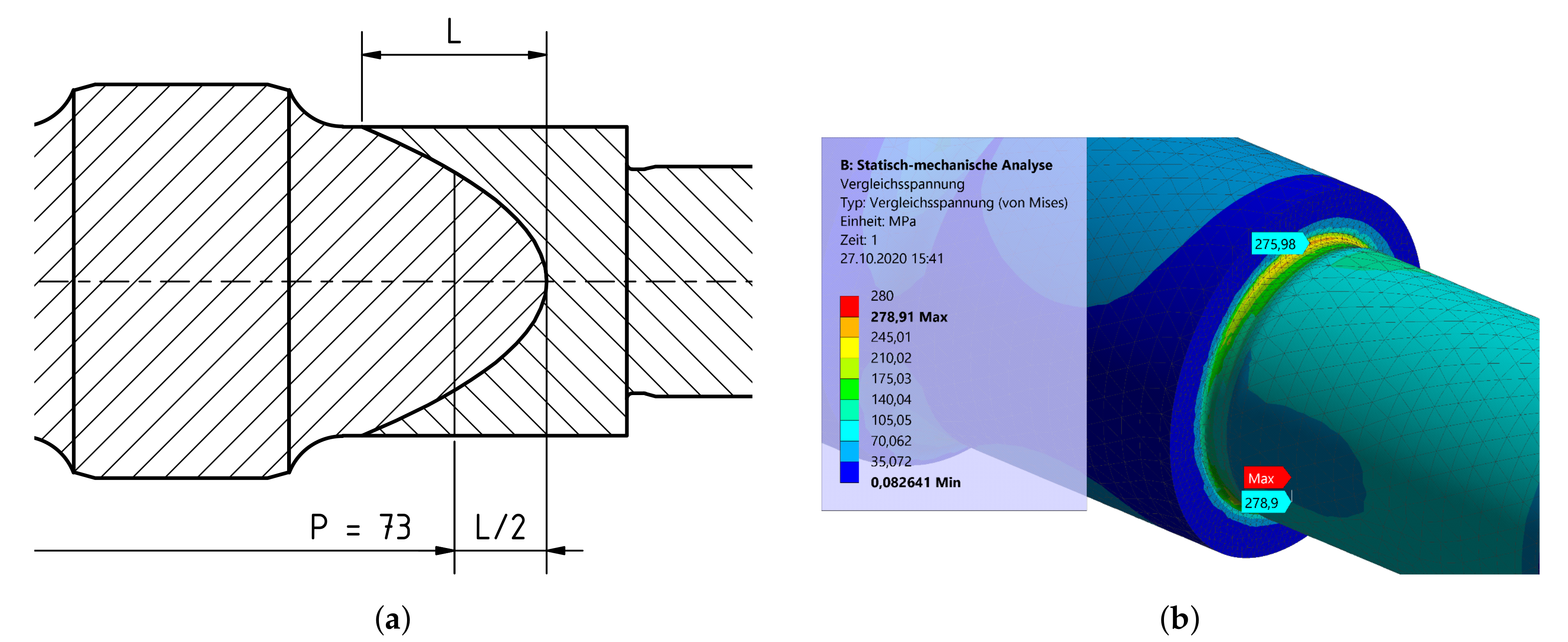
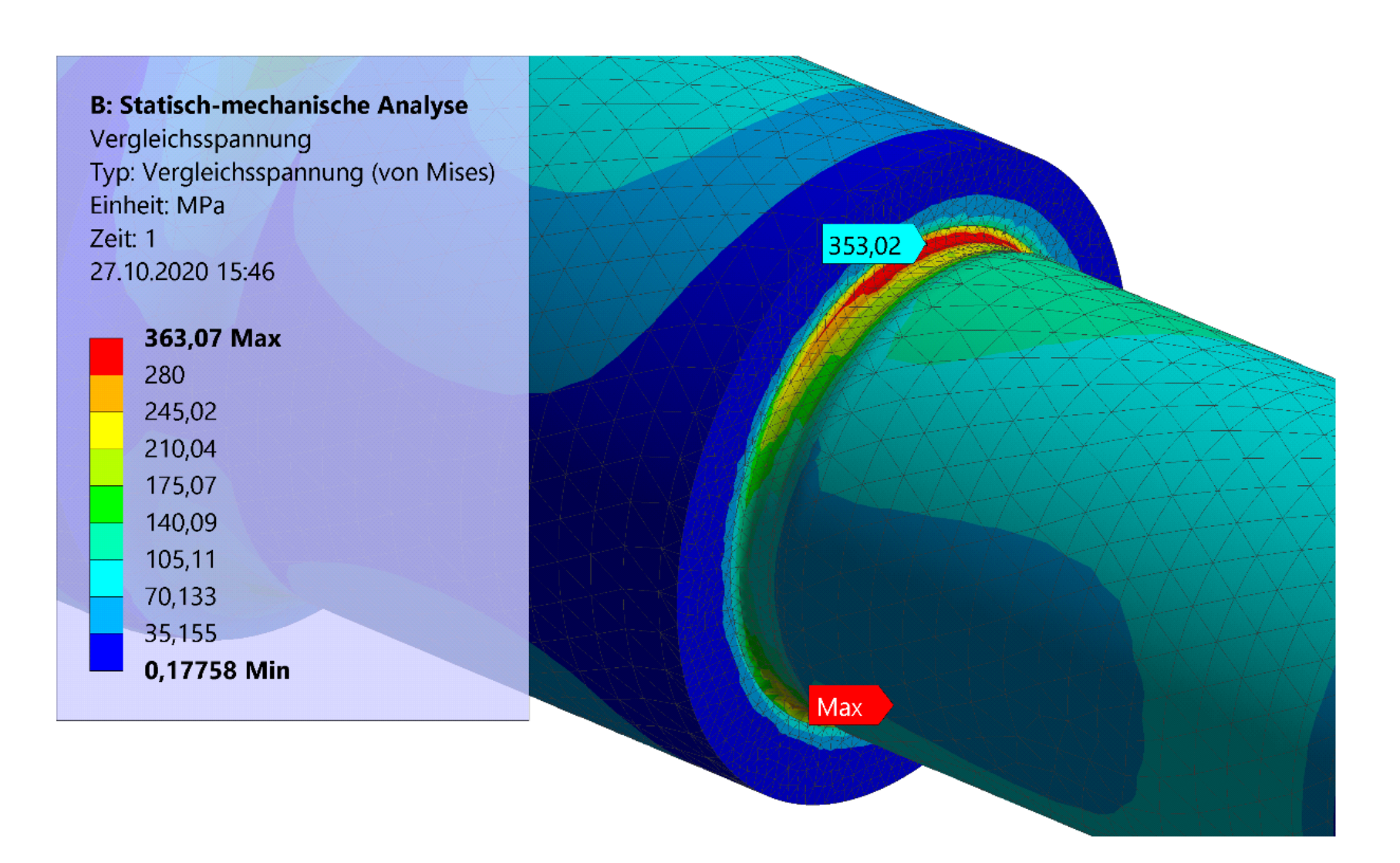
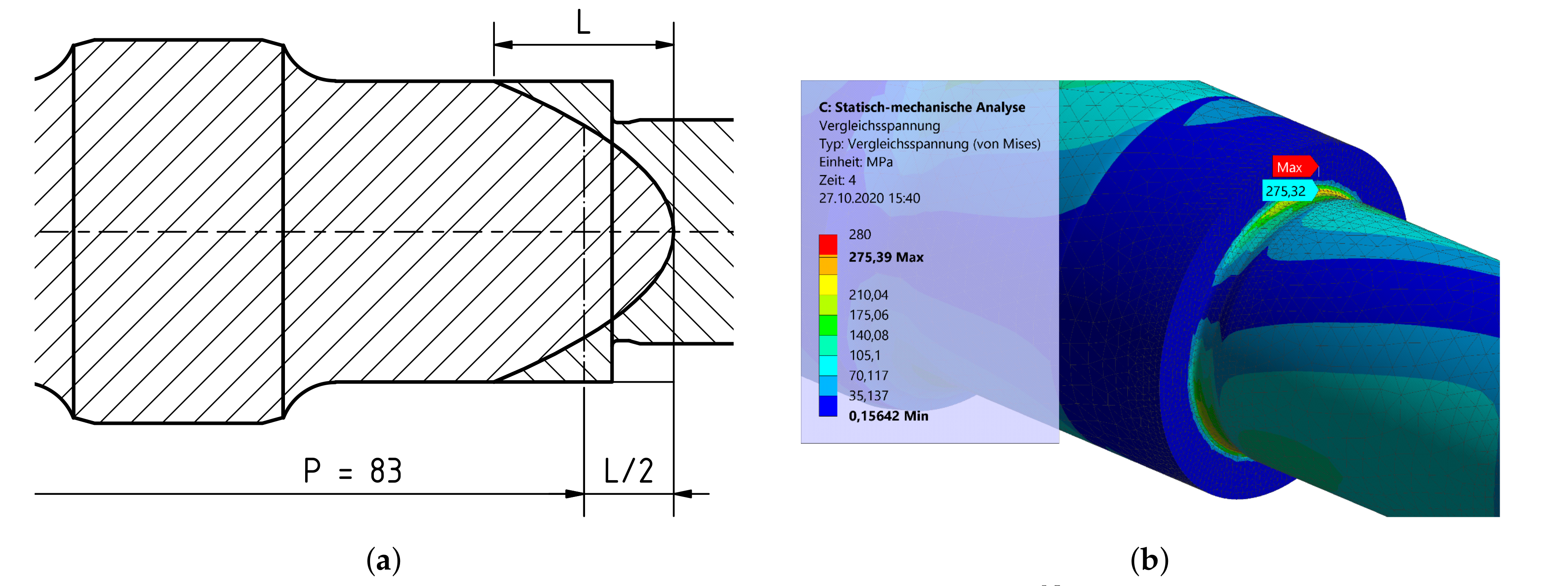
| Position | v. Mises Stress at 5.5 kN | v. Mises Stress at 8 kN | Weight |
|---|---|---|---|
| 73 mm | 278.9 MPa | 353.02 MPa | 245.61 g |
| 83 mm | – | 275.39 MPa | 264.05 g |
Publisher’s Note: MDPI stays neutral with regard to jurisdictional claims in published maps and institutional affiliations. |
© 2020 by the authors. Licensee MDPI, Basel, Switzerland. This article is an open access article distributed under the terms and conditions of the Creative Commons Attribution (CC BY) license (http://creativecommons.org/licenses/by/4.0/).
Share and Cite
Brockmöller, T.; Siqueira, R.; Gembarski, P.C.; Mozgova, I.; Lachmayer, R. Computer-Aided Engineering Environment for Designing Tailored Forming Components. Metals 2020, 10, 1589. https://doi.org/10.3390/met10121589
Brockmöller T, Siqueira R, Gembarski PC, Mozgova I, Lachmayer R. Computer-Aided Engineering Environment for Designing Tailored Forming Components. Metals. 2020; 10(12):1589. https://doi.org/10.3390/met10121589
Chicago/Turabian StyleBrockmöller, Tim, Renan Siqueira, Paul C. Gembarski, Iryna Mozgova, and Roland Lachmayer. 2020. "Computer-Aided Engineering Environment for Designing Tailored Forming Components" Metals 10, no. 12: 1589. https://doi.org/10.3390/met10121589
APA StyleBrockmöller, T., Siqueira, R., Gembarski, P. C., Mozgova, I., & Lachmayer, R. (2020). Computer-Aided Engineering Environment for Designing Tailored Forming Components. Metals, 10(12), 1589. https://doi.org/10.3390/met10121589