Abstract
Laser cutting technology is one of the basic approaches used for thermal processing of parts fabricated from almost all engineering materials. Various types of lasers are utilized in the industry with different attendant gases such as nitrogen or argon. When the laser beam interacts with a metal surface, the area underneath is heated to the melting point. This liquid or vaporized metal is ejected from the kerf area to the surrounding atmosphere by attendant gas and becomes undesirable waste in the form of powder. In the presented work, the X-ray diffraction, scanning electron microscopy, electron backscatter diffraction, transmission electron microscopy, and energy-dispersive X-ray spectroscopy methods were used to analyze AISI 304 stainless steel, which was cut by a semiconductor fiber laser, and the waste powder generated during the laser cutting process. The results suggest that this waste material may be reused for industrial applications such as additive manufacturing.
1. Introduction
Laser cutting is a technology widely used in machine industry as a fast and precise way of processing various materials. During the past few decades, it has developed significantly, and it offers a wide range of applications [1]. Among others, it is often used for machining of metallic materials such as steels, including stainless steels. With this technology, it is possible to produce variously shaped components of high precision and with a clean edge of cut [2]. Laser cutting can serve for materials disassembly in waste management too [3,4]. In fact, laser beam irradiation is also used in other metallurgical technologies, such as welding processes [5] or laser surface alloying, which can improve material properties (e.g., increase its hardness) [6]. Laser cutting is based on targeting a high-power laser beam on the material to be cut. When the laser beam impinges on a metal surface, the local temperature increases to the melting point, which results in melting the material at this place. This liquid is ejected from the kerf area to the surrounding atmosphere by gas which is blown from the nozzle of the device. Due to the principle of minimum energy, the droplets of ejected material usually acquire spherical shapes [7,8]. When passing through the atmosphere, these droplets subsequently solidify again and become waste which is usually thrown away [9].
In general, laser cutting compared to other cutting technologies produces less cutting dross, because the laser beam creates narrower kerfs [10]. Even so, during laser cutting of, e.g., steels, a significant amount of dross is produced this way [9]. According to the representatives of companies performing laser cutting, a typical industrial laser cutting machine can produce approximately 200 L of powder waste per month during its normal operation. This waste material causes problems for these companies because there is still a lack of available usage possibilities for this waste material and it is difficult to dispose of it in a legal way.
In these days, in developed countries, there is growing pressure on the utilization of waste materials formed by industrial production; these efforts also concern the waste coming from laser cutting of steel. One related advantage of the particulate waste material generated during industrial laser cutting is that it is captured by air filters that are a part of the laser cutting device. Therefore, it is easy to collect considerable amounts of this powder for further potential usage.
Until now, several studies focused on properties of small dross particles produced by laser cutting of various steels have been conducted to find new ways of using this waste material. It was found that these powder particles can serve as a material for manufacturing of metal parts by powder metallurgy [11]; they also have a potential to be used as a carrier for different substances, e.g., pesticides, medical drugs, or fertilizers [9]. Microscopic spheroidal particles obtained by laser cutting of steel were also studied to determine the feasibility of using this technique for producing microscopic particles for nuclear applications, specifically for nuclear fuels manufacturing [12], and some potential for this was found here. Great attention is paid also to health risks connected with such tiny dross particles coming from laser cutting and related methods of material processing [10,13]. These examples show that it is appropriate to carry out further research of dross particles obtained by laser cutting of various steel materials under various conditions.
According to the extent of our knowledge, the waste products created during a semiconductor fiber laser cutting with attendant nitrogen gas have not been characterized yet. In this study, we analyzed a widely used AISI 304 stainless steel and dross particles formed from this material by cutting it using a semiconductor fiber laser. These analyses were done by the X-ray diffraction, scanning electron microscopy, electron backscatter diffraction, transmission electron microscopy, and energy-dispersive X-ray spectroscopy. The obtained results should contribute to the research of new ways of reusing this powder waste material as well as to assess health risks arising from these micro- and nanoparticles. It should be noted that the waste powder was collected during normal industrial operation of the laser cutting machine, whence without analyzing the influence of process parameters such as the laser power, laser focal length, or cutting speed.
2. Materials and Methods
In this study, analyses of the cutting products as well as of the cut material are presented. The cutting products in a form of metal powders were collected after cutting of commercially available AISI 304 stainless steel (PN 0H18N9, EN 1.4301). The cutting process was conducted using BLM LT 5 automated fiber laser cutting machine from BLM company (Cantù, Italy) equipped with YLR-1000-MM-WC 1 kW semiconductor multi-mode laser from IPG. The laser wavelength was 1070 nm and its power was set to 300 W. The beam diameter during the cutting process was 0.1 mm and the distance between the laser nozzle and the cut material was 2 mm. The cutting speed was set to 2 mm s−1. The process parameters were typical for normal industrial operation of the laser cutting machine, as recommended by the manufacturer. In order to prevent oxidation of the laser-processed material, the cutting processes were carried out in a protective dry nitrogen atmosphere. The gaseous nitrogen was directed to the cutting area by a nozzle; the pressure in front of the nozzle was 16 bar. The gas flow plays an important role in the laser cutting process because it removes most of the molten and evaporated metal from the cutting area. The powder waste produced during the cutting process was transmitted by a dust extraction pipe system and collected in a powder collector.
Microstructure characterization of the steel waste material was performed by a scanning electron microscope (SEM) JEOL JSM-6480 (JEOL Ltd., Tokyo, Japan) equipped with Energy Dispersive X-ray Spectroscopy (EDS) detector from IXRF (Austin, TX, USA), and by Hitachi FlexSEM (Hitachi Ltd., Tokyo, Japan) scanning electron microscope equipped with SSD EDS detector from Oxford Instruments (Abingdon, UK) and with AZtecOne software package (version 3.3, Oxford Instruments, Abingdon, UK). Both microscopes were operated at an accelerating voltage of 20 kV. Electron backscattered diffraction measurements were performed on JEOL JSM-6480 scanning electron microscope using the accelerating voltage of 20 kV equipped with the electron backscattered diffraction (EBSD) system manufactured by Oxford Instruments (Abingdon, UK) with Nordlys II detector.
Microstructure analysis was also carried out using JEOL JEM-3010 high-resolution transmission electron microscope (TEM, JEOL Ltd., Tokyo, Japan) with 300 kV acceleration voltage, equipped with a Gatan 2k × 2k Orius™ 833 SC200D CCD camera (Gatan Inc., Pleasanton, CA, USA).
Phase analysis based on X-ray powder diffraction (XRD) measurements was done using Malvern Panalytical X’Pert diffractometer (Malvern Panalytical Ltd., Malvern, UK) with Cu anode (CuKα: λ = 1.5406 Å) working at an electric current of 30 mA, voltage of 40 kV, and equipped with a scintillation detector and a graphite monochromator on diffracted beam path. The use of the monochromator was dictated by the desire to exclude fluorescence, which was occurring when the copper anode was used to measure iron containing samples. The X-ray diffraction measurements were performed in an angular range of 2θ = 10–140° with 0.04° step. XRD phase analyses were carried out with the help of reference standards from the International Centre for Diffraction Data (ICDD) PDF-4+ database (ICDD, Newtown Square, PA, USA). Rietveld refinement was performed using FullProf computer software (version 6.30, J. Rodriguez-Carvajal at the Institut Laue-Langevin, Grenoble, France) [14].
3. Results and Discussion
3.1. Phase Analysis Based on the X-ray Diffraction and Electron Backscatter Diffraction
The obtained powders were analyzed using the X-ray diffraction method in order to determine the phase composition. The recorded diffraction pattern is shown in Figure 1. Phase analysis using the PDF-4 + ICDD database revealed the whole diffractogram can be described using four phases. The dominant phase is magnetite-like phase (Fe3O4, PDF: 04-013-9807) possessing a cubic structure and space group. Phase composition analysis showed that the studied material also contains cubic wuestite-like phase (α-FeO, PDF: 01-080-3820), ferrite iron like phase (α-Fe, PDF: 04-006-4192) possessing the A2 type of structure, and austenite-like phase (γ-Fe, PDF: 00-052-0512) with A1 type of structure. A detailed analysis based on X-ray diffraction measurements using Rietvield method was performed. The quantitative analysis showed that 74% of the studied material was magnetite-like phase. Detailed data of the experiment is demonstrated in Table 1.
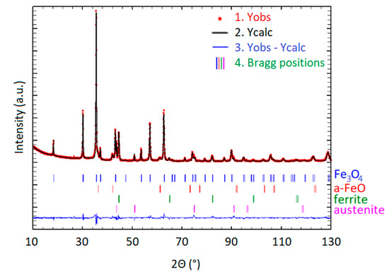
Figure 1.
X-ray diffraction (XRD) pattern with the Rietveld refinement results. Red circles indicate measured data points, the black line represents the calculated pattern, and the green line is the difference curve. The red, blue, green, and purple vertical lines below the data points indicate Bragg positions for the magnetite, α-FeO, α-Fe, and γ-Fe peaks, respectively.

Table 1.
Data of the Rietveld analysis performed on XRD profile of the studied material.
In order to support the phase analysis results from the X-ray diffraction, electron backscatter diffraction (EBSD) measurements were also performed (Figure 2). Due to the sample morphology—spherical particles—it was possible to measure only the top areas of the waste particles.

Figure 2.
Electron backscatter diffraction (EBSD) measurements of the particle samples: (a) morphology of the selected particle, (b) electron backscatter diffraction patterns, (c) EBSD pattern indexed to the magnetite structure.
Obtained Kikuchi diffraction patterns were indexed by the magnetite phase. The performed measurements confirmed that the spherical particles obtained from the powder waste are composed of the Fe3O4 phase. The other phases were not observed by the EBSD method. The presence of only the oxide layer can be explained by the penetration depth of the EBSD method. The diffraction information of an EBSD method has been described to originate from a small area extending approximately 10–40 nm at most from the sample surface.
3.2. Microstructure Analysis of the Steel Workpiece after Cutting
In order to analyze the surface of the material after laser cutting, the scanning electron microscopy and energy dispersive spectroscopy methods were applied. The cut material was analyzed on both the upper and the bottom side, the direct surface of the cut was studied too (Figure 3a,b and Figure c, respectively). As can be seen (Figure 3b), the laser cutting process starts by focusing the laser beam on the marginal part of the desired element, and a small hole through the material is burned. This puncturing of the cut object aims to create a steam channel—a die with walls covered with liquid metal and filled with metal vapors. This stage of the cutting process depends to a large extent on the reflectivity of the metal to be cut. Aluminum and copper are characterized by a high reflectivity, so they require much higher beam power to start the laser cutting process. After the creation of the die throughout the material, the laser beam acts as a linear energy source which is cutting, melting, and evaporating the material through its entire thickness. The cutting process is carried out with a set cutting speed and the desired shape of the cut is created.
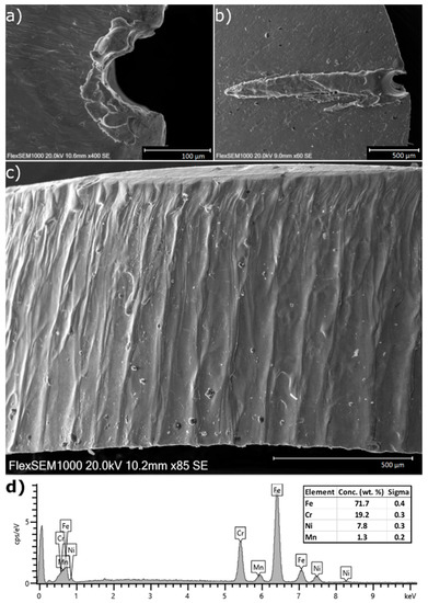
Figure 3.
Scanning electron microscope (SEM) images of the laser-cut material: (a) top view, (b) bottom view, (c) cut surface, and (d) Energy dispersive X-ray spectroscopy (EDS) spectra collected from the cut surface.
As can be seen in the SEM images, the initial penetration stage can cause a creation of molten material (Figure 3b). This is the reason why the cutting process starts on the outer part of the desired element in order not to affect the surface and the desired dimensions of the final element. The cut surface is clean and smooth with seldom visible melting lines of the material. The process is conducted in the protective gas atmosphere, and due to that, the surface oxidation process is suppressed. The recorded EDS spectra (Figure 3d) show only a slight presence of the oxygen. This is a great advantage of the laser cutting process in protective gas atmosphere due to the possibility to use the final cutting products without the necessity of further chemical or mechanical removal of oxide layers.
3.3. Microstructure Analysis of the Powder Waste
The resulting powders collected after the whole cutting process are composed mainly of spheroidal particles (Figure 4a,b). In the powder material, plate-like particles also occur, which seem to be a waste material that was directly cut. The performed observation (Figure 4d) showed that the spheroidal particles are composed of outer shells with dendritic character. Some of the particles have hollow centers with clearly visible octahedral particles (Figure 4e). Based on the SEM images, a size distribution analysis of the powder particles and the octahedral crystals was performed. The image analysis was performed using ImageJ software. For the analysis of powder particles diameters, 662 particles were taken into account. The obtained size distribution is presented in Figure 5a. The particles diameter distribution can be described using lognormal distribution with high correlation factors. The center of the distribution is 21.7 (4) μm with a width of 0.67 (1) μm. Based on the fitting procedure, the mean particle dimeter was determined to 27.2 (7) μm with a standard deviation of 20.6 (9) μm. Additionally the circularity of particles was analyzed (inset in Figure 5a). The obtained results indicate that the observed particles exhibit almost perfectly spherical shape—median of the distribution was determined to be 0.98.
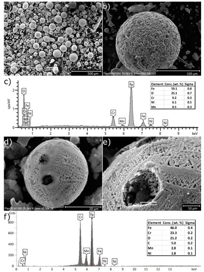
Figure 4.
SEM microstructure images of the powder waste material after laser cutting process: (a,b,d,e) examples of particles with corresponding EDS spectra collected from (c) surface and (f) particle interior.
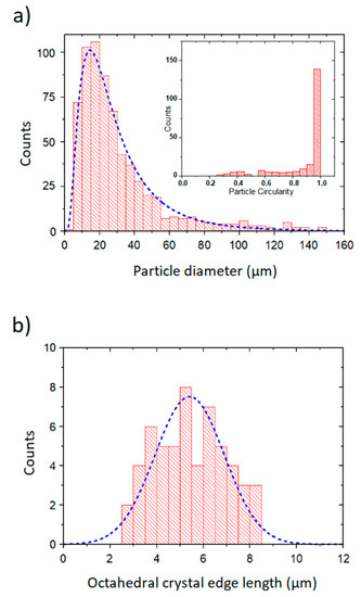
Figure 5.
Size distribution for the (a) spherical particles and (b) octahedral inner crystals with corresponding distribution curves marked by blue lines. The inset shows the distribution of particles circularity.
The size distribution of octahedral crystals (octahedrons’ edges) is presented in Figure 5b. For this analysis, 56 particles were taken into account. The crystals edge length distribution can be described as a Gaussian distribution, the Gaussian curve fitting is also shown in Figure 5b. The mean value of octahedron edge length (center of the distribution) is 5.4 (2) μm with a standard deviation of 3.7 (5) μm.
The studied samples also contained nanoparticles which were not observed by the SEM. In order to study these nanoparticles, transmission electron microscopy (TEM) methods were applied. First, the powder material was dispersed in isopropanol solution. After 30 min of the ultrasonic bath, this material was left without intervention for 2 min to sediment heavy particles. From the liquid solution, a sample for a TEM was prepared: a droplet of the solution was deposited on the TEM carbon grid using a pipette. The performed measurements showed that the powder waste material also contains nanoscale particles similar to those observed by Cabanillas in [7]. A representative image of these nanoparticles is given in Figure 6.
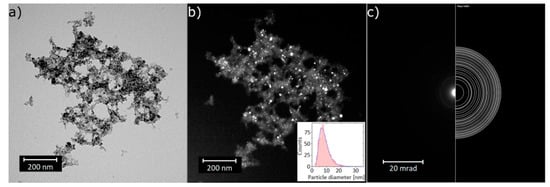
Figure 6.
Transmission electron microscope (TEM) images of the powder waste particles recorded in (a) a bright field and (b) a dark field, (c) left part: electron diffraction pattern from the area shown in (a), right part: theoretical diffraction rings for the magnetite phase.
The TEM images clearly show the nanoscale character of the powder waste particles. The obtained electron diffraction pattern indicates that the observed nanoparticles are a magnetite phase, the dark field images allowed to find the size distribution of these particles. Based on the analysis of 616 particles, the average diameter was determined to be 8.5 (1) nm with a standard deviation equal to 3.5 (2) nm. The particle size distribution follows the lognormal statistics too.
With respect to the results described above, it can be stated that the powder particles are composed mainly of a mixture of a magnetite (Fe3O4) phase. The EDS analysis showed that the obtained particles contain all the chemical elements of the initial steel material (Figure 4c,f). Additionally, the presence of oxygen in the particles is clearly visible. The balls’ oxidation process occurs due to the presence of oxygen outside the protective nitrogen atmosphere when the molten or vaporized material is blown away from the cutting area by a supplied stream of gas.
To assess a spatial distribution of chemical elements inside the particles, EDS analysis was done also for microparticle cross-sections. The powder material was mixed with carbon resin and this mixture was thermally hardened and polished in order to reveal the inner structure of the particles. The EDS spectra were taken from various distances from the particle center, as shown in Figure 7. In this case, a total of 26 spectra were taken and elemental compositions of the measured areas were mutually compared. The results for the most abundant elements are shown in Figure 8 (carbon was excluded from the evaluation due to a possible presence of parasitic EDS signals from the carbon substrate). It can be seen that the elemental distribution is fairly uniform. This uniformity was verified by SEM images taken in a backscattered electrons mode (see Figure 9); the uniform intensity of the cross-section shows that there are no fluctuations of elemental content in the bulk. In this figure, a typical crystalline structure with gaps can be seen too.
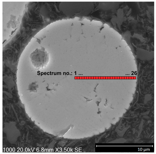
Figure 7.
Microparticle cross-section with highlighted areas from which the EDS spectra were taken.
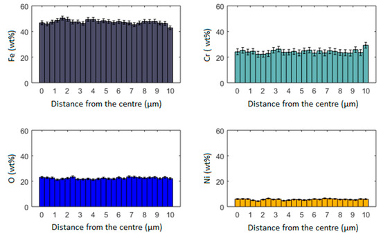
Figure 8.
The spatial distribution of chemical elements inside the particle.
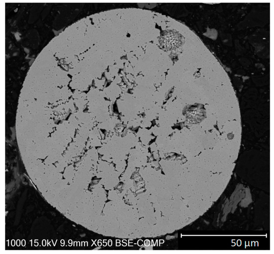
Figure 9.
Microparticle cross-section observed in a backscattered electrons mode.
The cutting process is based on material melting under the laser beam; the molten material is removed by the accompanying gas stream. In the presented situation, the gas also has an additional function—it prevents the oxidation of the cut surface. The material mass removal rate from the kerf is related to the molten layer and dross ejection. The molten layer breadth increases with higher laser power and decreases with raising accompanying gas pressure. During the cutting process, the accompanying gas creates a boundary layer flow over the molten metal surface, and heat transfer from liquid surface to boundary layer flow occurs. The accompanying gas additionally increases the velocity of the melt surface in the direction of the gas stream. Furthermore, the fragmentation of molten material takes place and the networks of ligaments are created, moving in the direction of the accompanying gas stream. Thus, the molten layer created on the cut surface is dragged away by the accompanying gas [8]. Furthermore, due to the velocity difference between the accompanying gas and the produced ligaments, the droplets of the molten metal are formed. Additionally, some small satellite droplets can also be created between the major droplets due to high aerodynamic forces and instabilities related to the fragmentation process. If a droplet is shaped at an early stage in the kerf, it may divide into smaller droplets due to the resistance in a high velocity environment—this process is involved in a secondary atomization [8]. Little particles are formed due to secondary fragmentation of the primarily created droplets. The creation of hollow and partially fractured particles is a result of rapid cooling of the surface. Simple surface tension considerations are satisfactory to justify the spherical geometry of the produced particles—the surface tension results in spherical shaping of the droplets during quenching after their ejection caused by laser ablation [12].
A great portion of the produced particles exhibit a fine dendritic structure with very few dendrites per particle and well-developed primary and secondary dendrite arms. Such a type of structure is a result of heterogeneous nucleation process occurring in strongly supercooled droplets. Heterogeneous nucleation is probable to occur during the solidification flight of fine particles owing to numerous collisions experienced by the fine particles. The growth of a dendrite across the whole particles is thus possible due to the high degree of supercooling occurring in the fine particles [15,16]. After that stage, the particles cool down, which can be likened to quenching.
4. Conclusions
Laser cutting technology is one of the basic technologies used for a thermal cutting of parts made mostly of all engineering materials. Laser cutting of metallic materials, which uses the liquid state technique of material removal, is used mainly for high alloy steels, cobalt alloys, titanium alloys, aluminum, and magnesium alloys and nickel superalloys. Nitrogen or argon usually serve as accompanying gases, the cut edges are then pure metallic, free from oxides, and they do not require any additional cleaning operations. As has been shown, the waste products consist of powder spherical microparticles with a mean diameter of 27.2 (7) μm. Additionally, nanoparticles were observed, whose mean diameter was determined to be 8.5 (1) nm. The analyses showed that the waste particles are composed mainly of magnetite and FeO having a chemical composition characteristic for the cut material—stainless steel. The spatial distribution of chemical elements inside the particles is fairly uniform. The size distribution and circularity of the observed microparticles is typical for powders used in additive manufacturing (optimal particle size for metal injection molding is said to be 10 to 38 μm, for cold spray 5 to 45 μm, and for laser melting 15 to 45 μm [17]); thus, this waste material shows a potential to be used as an input material for such industrial applications [18,19,20,21]. In order to increase the control of the additive manufacturing process, further sifting of the powder material could be performed. According to the literature, optimal material for laser sintering technique is powder with bimodal size distribution of its particles [22,23]. The sifting of the powder could additionally ensure such a state. Prior to industrial application of the powder waste material in additive manufacturing processes, the full understanding of the powder behavior during such processes is needed. In order to evidence the possibility of application of the obtained powders, further work is in progress. The presence of nanoscale particles also brings health risks connected with inhalation of this material. Nanoscale particles (dimension < 100 nm) can access the bloodstream by penetrating the alveolar epithelium. Further, these ultrafine particles have increased inflammatory potential in addition to a large deposition efficiency within the pulmonary system [24].
Author Contributions
Conceptualization, M.Z., J.L., and Z.J.; methodology—M.Z., J.L., P.Ś., and K.P., resources and material manufacturing—Z.J.; investigation—M.Z., J.L., P.Ś., and K.P.; writing—original draft preparation, J.L. and M.Z.; data analysis—M.Z., J.L., P.Ś., and K.P.; All authors contributed to writing—review and editing. All authors have read and agreed to the published version of the manuscript.
Funding
The presented research was financially supported by the Specific research project 2107/2019 at the Faculty of Science, University of Hradec Králové.
Acknowledgments
The authors would like to express their great gratitude to Grzegorz Dercz for invaluable help in XRD analysis.
Conflicts of Interest
There are no conflicts of interests to declare.
References
- Teixidor, D.; Ciurana, J.; Rodriguez, C.A. Dross formation and process parameters analysis of fibre laser cutting of stainless steel thin sheets. Int. J. Adv. Manuf. Technol. 2014, 71, 1611–1621. [Google Scholar] [CrossRef]
- Amulevičius, A.; Mažeika, K.; Sipavičius, Č. Oxidation of stainless steel by laser cutting. Acta Phys. Pol. A. 2009, 115, 880–885. [Google Scholar] [CrossRef]
- Krot, K.; Chlebus, E.; Kuźnicka, B. Laser cutting of composite sandwich structures. Arch. Civ. Mech. Eng. 2017, 17, 545–554. [Google Scholar] [CrossRef]
- Khan, A.; Blackburn, J. Laser size reduction of radioactively contaminated structures. J. Laser Appl. 2018, 30, 032607. [Google Scholar] [CrossRef]
- Lisiecki, A.; Kurc-Lisiecka, A. Automated Laser Welding of AISI 304 Stainless Steel by Disk Laser. Arch. Metall. Mater. 2018, 63, 1663–1672. [Google Scholar]
- Brytan, Z. The corrosion resistance of laser surface alloyed stainless steels. Arch. Metall. Mater. 2018, 63, 2039–2049. [Google Scholar] [CrossRef]
- Cabanillas, E.D. Transmission electron microscopy observation of nanoparticles obtained by cutting power laser. J. Mater. Sci. 2004, 39, 3821–3823. [Google Scholar] [CrossRef]
- Yilbas, B.S.; Aleem, B.J.A. Dross formation during laser cutting process. J. Phys. D Appl. Phys. 2006, 39, 1451–1461. [Google Scholar] [CrossRef]
- Mercader, R.C.; Marchetti, S.G.; Bengoa, J.F.; Punte, G.; Cabanillas, E.D. Characterization of scraps produced by the industrial laser cutting of steels. Hyperfine Interact. 2010, 195, 249–255. [Google Scholar] [CrossRef]
- Lopez, A.; Assunção, E.; Pires, I.; Quintino, L. Secondary emissions during fiber laser cutting of nuclear material. Nucl. Eng. Des. 2017, 315, 69–76. [Google Scholar] [CrossRef]
- Cabanillas, E.D.; Creus, M.F.; Mercader, R.C. Microscopic spheroidal particles obtained by laser cutting. J. Mater. Sci. 2005, 40, 519–522. [Google Scholar] [CrossRef]
- Elihn, K.; Berg, P. Ultrafine particle characteristics in seven industrial plants. Ann. Occup. Hyg. 2009, 53, 475–484. [Google Scholar] [PubMed]
- de Souza, J.; Oliveira-Motta, C.A.; Machado, T.G.; Giacomin, A.; Arabi, H.M.A. Analysis of Metallic Waste from Laser Cutting for Utilization in Parts Manufactured by Conventional Powder Metallurgy. IJRES 2016, 4, 1–5. [Google Scholar]
- Rodriguez-Carvajal, J. Recent advances in magnetic structure determination by neutron powder diffraction. Physica B 1993, 192, 55–69. [Google Scholar] [CrossRef]
- Pryds, N.H.; Pedersen, A.S. Rapid solidification of martensitic stainless steel atomized droplets. Metal. Mater. Trans. A 2002, 33A, 3755–3761. [Google Scholar] [CrossRef]
- Duflos, F.; Stohr, J.F. Comparison of the quench rates attained in gas-atomized powders and melt-spun ribbons of Co- and Ni-base superalloys: Influence on resulting microstructures. J. Mater. Sci. 1982, 17, 3641–3652. [Google Scholar] [CrossRef]
- Powder Metallurgy and Additive Manufacturing. Malvern Panalytical. Available online: https://www.malvernpanalytical.com/en/assets/MRK2319-02_tcm50-55142.pdf (accessed on 6 May 2020).
- Qi, H.B.; Yan, Y.N.; Lin, F.; He, W.; Zhang, R.J. Direct metal part forming of 316L stainless steel powder by electron beam selective melting. Proc. Inst. Mech. Eng. Part B J. Eng. Manufact. 2006, 220, 1845–1853. [Google Scholar] [CrossRef]
- Sun, Z.; Tan, X.; Tor, S.B.; Yeong, W.Y. Selective laser melting of stainless steel 316L with low porosity and high build rates. Mater. Des. 2016, 104, 197–204. [Google Scholar] [CrossRef]
- Kong, D.; Ni, X.; Dong, C.; Lei, X.; Zhang, L.; Man, C.; Yao, I.; Cheng, X.; Li, X. Bio-functional and anti-corrosive 3D printing 316L stainless steel fabricated by selective laser melting. Mater. Des. 2018, 152, 88–101. [Google Scholar] [CrossRef]
- Sun, P.; Fang, Z.Z.; Xia, Y.; Zhang, Y.; Zhou, C. A novel method for production of spherical Ti-6Al-4V powder for additive manufacturing. Powder Technol. 2016, 301, 331–335. [Google Scholar] [CrossRef]
- Boley, C.D.; Khairallah, S.A.; Rubenchik, A.M. Calculation of laser absorption by metal powders in additive manufacturing. Appl. Opt. 2015, 54, 2477–2482. [Google Scholar] [CrossRef] [PubMed]
- Zhou, J.; Zhang, Y.; Chen, J.K. Numerical simulation of random packing of spherical particles for powder-based additive manufacturing. J. Manuf. Sci. Eng. 2009, 131, 031004. [Google Scholar] [CrossRef]
- Elmes, M.; Gasparon, M. Sampling and single particle analysis for the chemical characterization of fine atmospheric particulates: A review. J. Environ. Manag. 2017, 202, 137–150. [Google Scholar] [CrossRef] [PubMed]
Publisher’s Note: MDPI stays neutral with regard to jurisdictional claims in published maps and institutional affiliations. |
© 2020 by the authors. Licensee MDPI, Basel, Switzerland. This article is an open access article distributed under the terms and conditions of the Creative Commons Attribution (CC BY) license (http://creativecommons.org/licenses/by/4.0/).