1. Introduction
In recent times there has been a strong demand in the transport sector, which includes the aeronautical, aerospace and automobile industries, in terms of reducing the energy consumed, mainly due to economic and environmental constraints. This reduction allows vehicles to transport a greater number of passengers or goods, over an increased distance, or increased fuel efficiency. An important method of reducing fuel consumption is to achieve a reduction in the mass of vehicles, by using lighter materials, among which are light alloys such as titanium, aluminum or magnesium, which have excellent ratio density/mechanical strength [
1,
2,
3,
4,
5,
6].
The parts used in the aeronautical sector, in addition to maintaining the characteristics of strength, rigidity and low density, must comply after processing and meet very strict standards in terms of quality requirements, among which are dimensional, shape and roughness [
1,
2]. Furthermore, due to environmental constraints, the processing of these parts must be carried out in an environmentally sustainable way.
The maintenance and repair of the used parts is especially important, due to the high cost derived from the imposed requirements, which determines that these parts are repaired and reused instead of being replaced by new ones. Associated with repair or maintenance, the cost must be considered as a determining factor, mainly in the aeronautical sector, derived from loss of income due to the standstill of the aircraft. Therefore, these activities must be planned and executed reducing the time used and, with it, the associated cost [
1,
7]. In this context, the repair and/or maintenance tasks are framed, consisting of core drilling or re-drilling a previous hole, to a slightly larger diameter, to subsequently assemble it, usually by riveting. This repair process must be carried out carefully to avoid the appearance of cracks, for which consequences can be catastrophic in the aeronautical sector [
2,
3].
Magnesium alloys have a set of characteristics such as low specific cutting strength, low tool wear, short and brittle chips and high thermal conductivity, which make them materials with excellent machining properties; allowing high feed rates and depths of cut to be used, resulting in machined parts with good surface finish and close geometric tolerances, allowing them to perform all common machining operations [
8,
9,
10]. Nevertheless, this machining process presents two problems that must be considered and that concern security. Firstly, there is the risk of ignition when the removed chips reach the temperature of 450 °C, as they are able to create an explosion when their size is very small, and they are in the form of particles. Secondly, if the normal emulsified cutting fluids in water are used, magnesium can react with them to form highly flammable and potentially explosive hydrogen atmospheres [
10,
11].
All standard machining operations can be performed on magnesium alloys without great difficulty, with drilling being one of the most common. In the aeronautical sector it is especially important due to the high number of joints that are used, mainly by riveting, that require a previous hole. Taking into account that the number of holes can exceed one million, the risk of surface cracks and their growth in drilled holes is notable, which could jeopardize the structural integrity of vehicles [
2,
3,
6,
12,
13].
Drilling of magnesium alloys has been extensively studied, focusing mainly on the influence of cutting conditions on response variables, particularly, in the surface quality, the forces, the torque and the wear of the tool. The studied cutting conditions vary between 35 and 188 m/min for the cutting speed, and between 0.05 and 0.7 mm/r for the feed rate. Only Weinert et al. [
12] used high-performance cutting conditions, reaching up to 1100 m/min and 1.2 mm/rev in cutting speed and feed rate, respectively. Regarding the surface quality, most of the studies quantified it using the arithmetic mean of the roughness
Ra, also studying the microhardness of the machined surfaces [
3,
10,
12,
14,
15,
16,
17,
18]. Boothroyd and Knight [
19] approached the study of surface roughness distinguishing between the ideal roughness, which was a result of the geometry of the tool and the machining speed, and the natural one, which was the result of irregularities in the cutting process, such as vibrations, imperfections in the material structure or wear in the shape of the tool. These authors proposed an ideal surface roughness model for the case of a tool with a cutting edge, which is shown in Equation (1), in which
re is the radius of the tool and
f feed rate.
With respect to the optimization of the tool in solid drilling of magnesium alloys, Bhowmick and Alpas [
16] studied the influence of coating type, finding that diamond-like carbon coating increased tool life and decreased torque using minimum quantity lubrication (MQL) lubrication. Weinert et al. [
12] tested different twist drills geometries, finding great importance in terms of force and torque, obtaining lower values in drill with a point angle of 140° compared to 118°. Berzosa et al. [
10] studied the roughness of machined surfaces obtaining very good values of
Ra, getting better surface finish at lower speed and feed rate when using drills with a point angle of 135° compared to 118°.
Re-drilling processes have not been sufficiently researched in magnesium alloys. Berzosa et al. [
3] studied the influence of cutting parameters on the surface quality of dry machined surfaces, detecting that the parameter that had the greatest influence on roughness measured by
Ra was the type of drill used. Contrary to what might be expected in principle, no influence of feed rate on the roughness was found, this result being consistent with another study for the case of solid drilling in this type of alloy, with cutting parameters of the same order of magnitude [
10]. Rubio et al. [
2] investigated these operations for the case of hybrid components of Mg-Ti-Mg, studying the roughness in different locations of the component examined.
Considering that usually after the machining of holes for riveting, threading or mechanical assembly operation is performed, the presence of large burrs needs to be eliminated or kept under control. These burrs generally depend on the tool, the material of the piece and the cutting conditions. Burr height measurement is one of the most important challenges researchers face. The commonly used methods are of two types, using optical microscopes, or by contact, using coordinate measurement machines or height measurement instruments, among others [
20,
21,
22,
23].
In aluminum alloys similar to magnesium, such as aluminum AA7010 Abdelhafeez et al. [
20], found a strong influence between feed rate and cutting speed used with the height of the burr at the exit of the drill, making the measurements with an optical microscope. In AL6030/15%/SiC aluminum matrix composite material, Kamboj et al. [
22] found that the burr increased with feed rate, and decreased with increasing cutting speed, measuring at three points with a height measurement instrument. In the case of Ti-6Al-4V titanium alloys Dornfeld et al. [
23] found that the height of the burr increased with increasing cutting speed and decreased with increasing drill point angle, making the measurement using an optical microscope. Rivero et al. [
13] used the profile acquired by a roughness tester in the measurement process to quantify the height of the burr, corroborating the results by the same measurement with an optical microscope.
The most widely used tools for drilling operations are twist drills, which are manufactured with different geometries and materials, using various types of surface coatings, such as TiN or TiAlN, to name a few of the most widely used. Therefore, most of the tool manufacturers have a wide variety of drill types. On the market there are specialized drills available to be used for a certain group of materials, optimizing their design to obtain the most improved performance, whereas standard drills are designed to keep the right balance between covering a wide number of groups of materials and maintaining the performance.
The main tool manufacturers do not always consider magnesium alloys within their group of materials, so they should be included within the aluminum alloys, which are the most similar in terms of machining. In addition, in the framework of repair and maintenance workshops, there is a tendency to use twist drills with a wide range in terms of the materials in which they can be used, with the opposite occurring in production centers which are looking for high-performance processes.
The use of cutting tools that incorporate different advances in materials and coatings, improves the machining process; nevertheless, they are significantly more expensive. This is one of the factors that has favored the increasing use of tool sharpening operations, which allows their use for further applications, as it is the case of drilling tools. In addition, the use of drill sharpening machines has been remarkably extended, which allows for sharpening regardless of the geometry, material and coatings used in its manufacture. Currently most twist drills are sharp, representing significant cost savings [
24].
One possibility offered by sharpening drills is to be able to make variations in the geometry of drills. The geometry of tools is an important factor in the surface quality of machined surfaces in metallic materials in general and in magnesium alloys, affecting the forces and moments involved in machining and the durability of the tool [
25]. Borba et al. found that the type of drill sharpening was the main factor in terms of its influence on the height of the burr on aluminum alloys [
26]. Regarding the point angle of drills, in general, an increase in its value increases the height and the thickness of the burr [
24]. The main manufacturers recommend for magnesium alloys values between 118° and 135°; Astakhov proposed values between 130° and 140° [
27]. Thus, it is possible to adapt the drills that are available in workshops, for the specific material being machined, in such a way that both the performance of the drill and the operation, as well as the quality of the mechanized parts, are optimized.
The present work studies the influence of the cutting conditions and the geometry and composition of the tool on the surface roughness of holes made in UNS M11917 (AZ91D-F) magnesium alloy parts, on which re-drilling operations were carried out for maintenance and/or repair tasks. The objective is to determine how the parameters studied affect surface integrity. For this, a series of tests were carried out whose design of experiments is a full factorial analysis by analysis of variance (ANOVA), which allows the minimization of roughness and, at the same time, optimizes the productivity of the process, fully complying the requirements of the components. The analysis will be complemented by analyzing the height of the burrs and microhardness obtained and surface topology using images of the drilled holes, in order to generate a broader view of the quality of the drills made.
2. Materials and Methods
Two types of twist drill manufactured by Phantom (Van Ommen BV, Beekbergen, Gelderland, The Netherlands) were selected for drilling the holes, in accordance with DIN 1897 [
25]. The material of both types of drills is the same, high speed steel, differing only in that the first type is uncoated while the second type has a TiN coating, which is easily distinguishable by the golden color, for which manufacturer’s references are 11.160 and 11.161, respectively. The geometric characteristics, equal in both types, are; diameter 8 mm, total length 79 mm, a helix shape normal type N according to DIN 1836 [
28], with a length of 37 mm and sharpening split form C point in accordance with DIN 1412 [
29].
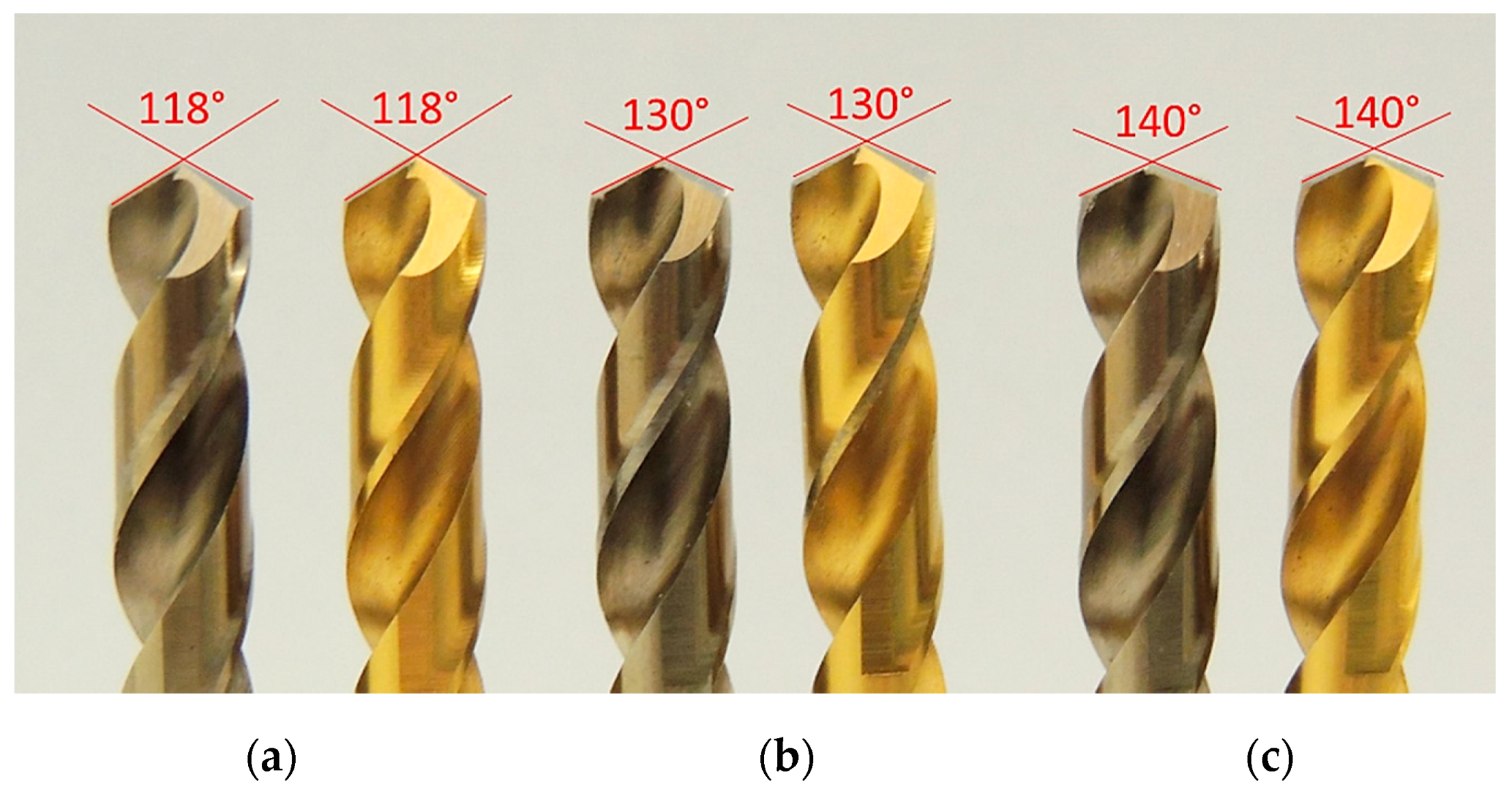
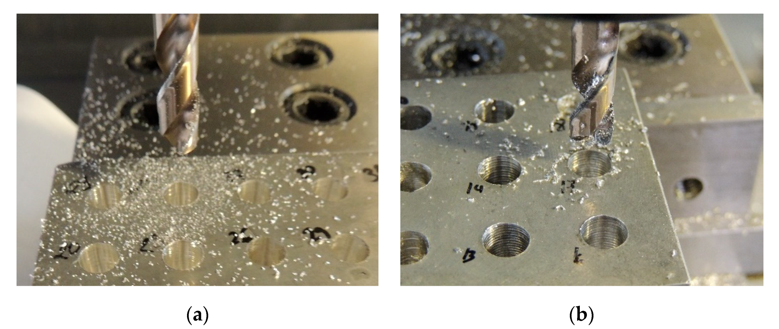
Both types of drill originally had a point angle of 135°, which was modified in the sharpening process of the drills to obtain the different point angles to be tested in the experiment. For this, a drill sharpener model 750X was used, manufactured by Darex (Darex Industrial, Ashland, OR, USA), which allows sharpening of drills with selectable point angles from 115° to 140°, allowing for sharpening the type C split form, being able to machine the hardest materials by using a diamond grinding wheel. The point angles to be tested were established at 118°, 130° and 140°, which can be seen for both types of drills in
Figure 1.
The material used to manufacture the test piece was UNS M11917 (AZ91D-F) magnesium alloy, produced by molding and supplied in the form of an ingot, which was machined by milling until obtaining a block measuring 110 mm × 62 mm × 50 mm. The chemical composition of the alloy as a percentage of mass is reflected in
Table 1. The microstructure and compounds that appear are important, since they determine the mechanical properties and machinability of the alloy. The presence of
β phase is located in the borders of the grains formed by
α phase, causing this compound a degradation in mechanical properties [
30,
31,
32].
The drilling tests were carried out using a Mikron VCE 500 numerical control vertical machining center (Mikron Machining, Agno, Switzerland), which has travels in X, Y and Z axes of 500, 400 and 500 mm, respectively, and a maximum rotation speed of 7500 rpm, which has a hydraulic clamp for fastening the pieces. The cutting speed was set at 60 m/min, which for a drill with a diameter of 8 mm determines a rotation speed of 2387 rpm. The feed rates were set at 0.4 and 0.8 mm/rev. These cutting parameters were established considering previous studies in this type of operation and framing it within the scope of maintenance and/or repair tasks.
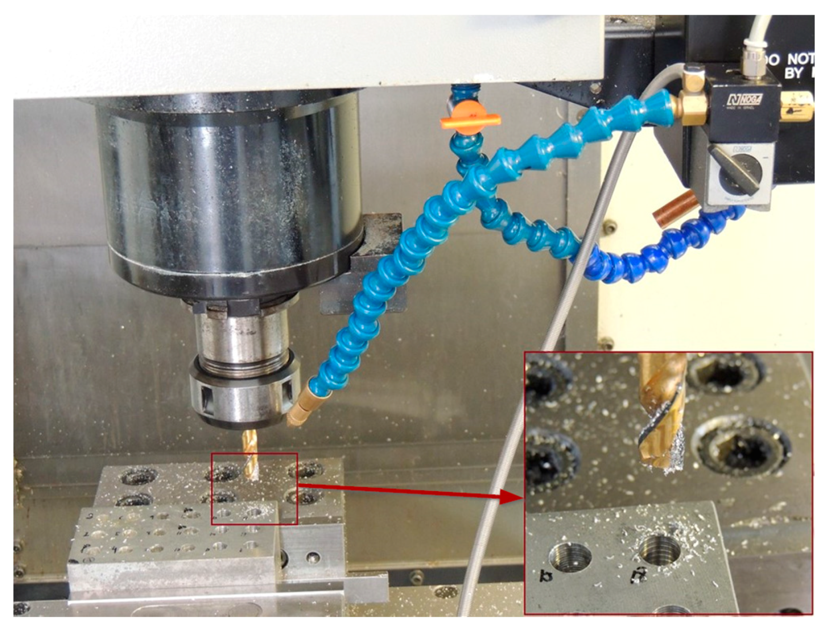
Two lubrication systems were considered: dry and minimum quantity lubrication (MQL), which allow for the environmental sustainability of drilling operations. The MQL system used, which can be seen in
Figure 2, is the model Noga Minicool (Noga Engineering & Technology Ltd., Shlomi, Israel), which has a supply flow regulation device, as well as an adjustable nozzle that allows one to regulate the dispersion of the flow. This flow was established at 40 mL/h, for which the mass of lubricant consumed in a certain period of time was measured, keeping the lubrication system regulations constant. The lubricating fluid was rhenus Nor SSL (Rhenus Lub GmbH & Co KG, Mönchengladbach, Germany), specially formulated for micro-spraying, whose characteristics are, viscosity at 40 °C of 4.7 × 10
−5 m
2/s and density at 20 °C of 0.92 g/mL.
Drilling operations were carried out enlarging some previous blind holes of 7.75 mm, up to a final diameter of 8 mm, which supposes a depth of cut of 0.125 mm. These conditions simulate the repair tasks in which they try to eliminate the minimum material, in order not to weaken the component. The drilling depth was 20 mm from the top surface of the specimen, performing a drilling cycle with the feed rate established and making the tool recoil quickly. After each of the individual tests, a photographic record was taken, and the work area was cleaned with compressed air.
The most used parameter for the evaluation of surface roughness is the arithmetic mean deviation of the roughness profile
Ra which is defined in ISO 4287:1997 [
33], which has been used in most of the drilling of alloys magnesium papers [
3]. It has the advantage of being easy to measure, giving general information on the roughness amplitude, but on the other hand, it has the disadvantage of lacking physical meaning, not distinguishing between peak and valley, and not offering information on profile length characteristics [
34]. Thus, the study of surface quality will be complemented with other parameters. The mean value of the peak-valley heights of the 5 sampling lengths,
Rz, and the mean spacing of the roughness at the centre line,
RSm, will alleviate the deficiencies mentioned above.
The roughness parameters were measured using a Zeiss Handysurf E-35A roughness tester (Carl Zeiss AG, Oberkochen, Baden-Württemberg, Germany), which allows us to visualize on a small display the calculated parameters, among which are the
Ra, Rz and
RSm. In addition to this, it is possible to export the measurement data to a computer, using the roughness tester software, creating a spreadsheet with these parameters and generating a graph with the roughness profile. To carry out the measurements, the roughness probe, which is portable, was grabbed by a special tool to a height gauge that us allows to position it at the desired height, placing the assembly, as well as the specimen on a surface plate, as can be seen in the
Figure 3. The parameters of the roughness tester were selected according to the ISO 4288 standard [
35], which establishes that for a roughness range between 0.1 and 2 µm of
Ra, the sampling length
lr is 0.8 mm and the evaluation length
ln 4 mm.
To determine the influence of the drilling depth, roughness was quantified at two different heights from the top face of the specimen. At the top height (TH) the measurements were made at a distance of 5.5 mm from the top surface of the hole, and at the bottom height (BH) at a distance of 15 mm also from the top surface of the hole. At each of these depths, roughness was measured at four points separated to 90°, so there was a total of eight measurements in each machined hole.
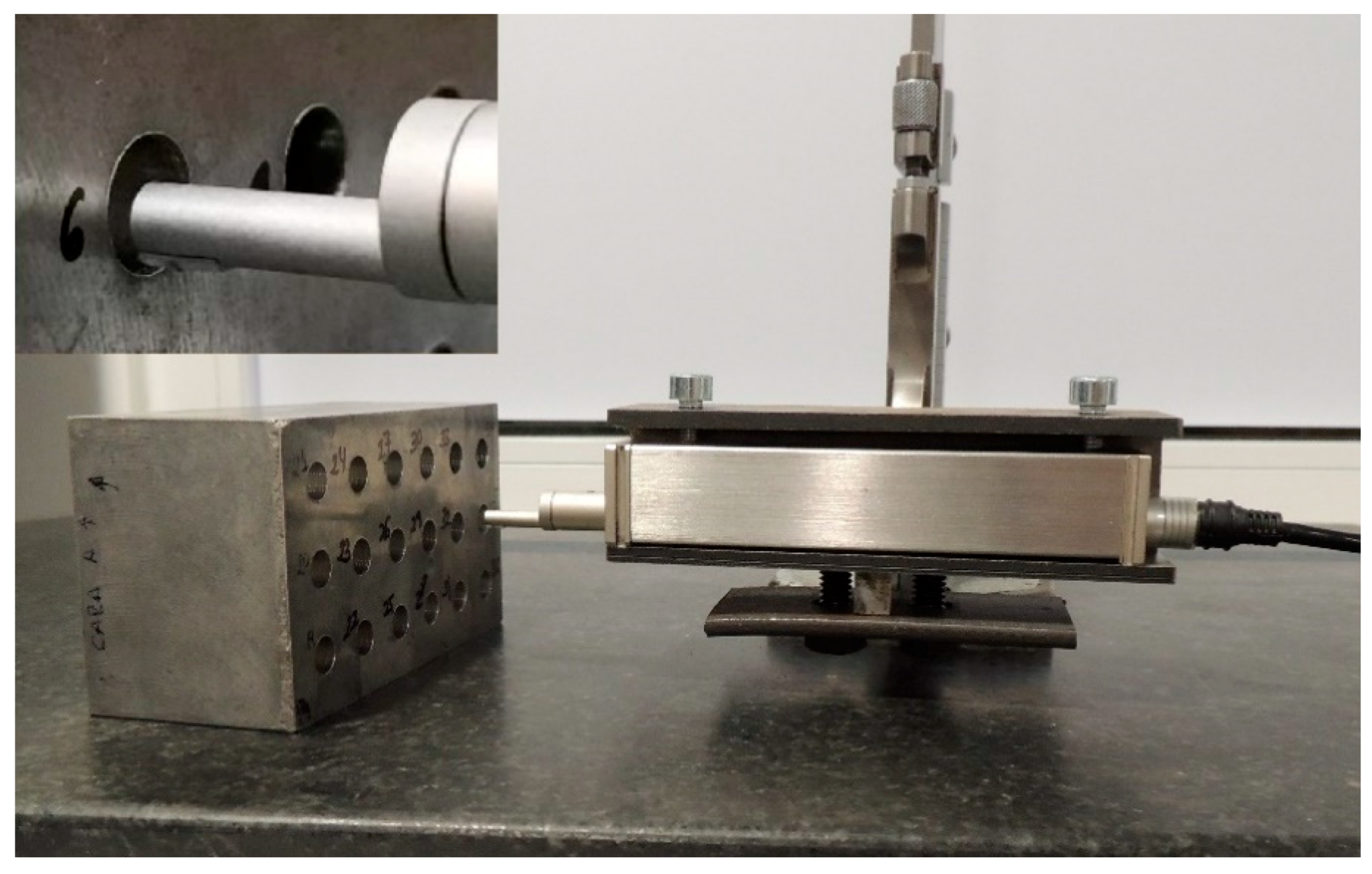
In addition to roughness, the height of the burr generated in the drilling process was evaluated. For this, the measurement was made using a lever-type dial indicator with a graduation of 0.01 mm, taking the measurements at four points on the edge of the hole, spaced at 90°, corresponding to the positions in the roughness measurement. For this, the lever-type dial indicator was placed on a fixed support, and the specimen was supported on two rectified cylinders, which when rolling allow the specimen to move in the measurement direction, all of the above was done on a granite surface plate, as can be seen in
Figure 4. The burr measurement process was started by zeroing on the top face of the specimen, and then moving the specimen slowly, identifying the highest point recorded by the dial indicator as the height of the burr. All in all, the height of the burr was measured at four points, and its average value allowed the height of the burr to be quantified.
Longitudinal sections of the selected holes were made in order to perform micro and macroscopic inspection of the machined surfaces. For this, a previously drilled specimen was machined, by milling in the radial direction to the center of the holes, using low cutting parameters and lubrication so as not to alter the properties of the alloy, and then machining by abrasion in a metallographic polishing machine until obtaining a flat and smooth surface. Subsequently, a cleaning was performed with an ultrasound machine and ethanol.
Microscopic images of the surface were taken using a Bresser Microcam II 12 MP digital camera (Bresser GmbH, Rhede, Germany) placed on a Nikon LV150 metallographic microscope (Nikon Metrology Europe, Leuven, Belgium) at different magnifications. There is a problem with these types of images, which is more accentuated on curved surfaces such as the case of the drilled interior surface, which is showing only a small part of the image correctly focused. For this reason, a digital image processing technique was used to improve the depth of field known as extended depth of field or extended depth from focus (EDF), which consists of expanding the depth of focus using the information from a series of images arranged in a sequence taken at different elevations of the Z axis of the lens of the objective. For this, the Stack Focuser plugin [
36] of the open ImageJ software was used, which is an adequate tool for the topographic reconstruction of surfaces [
37,
38].
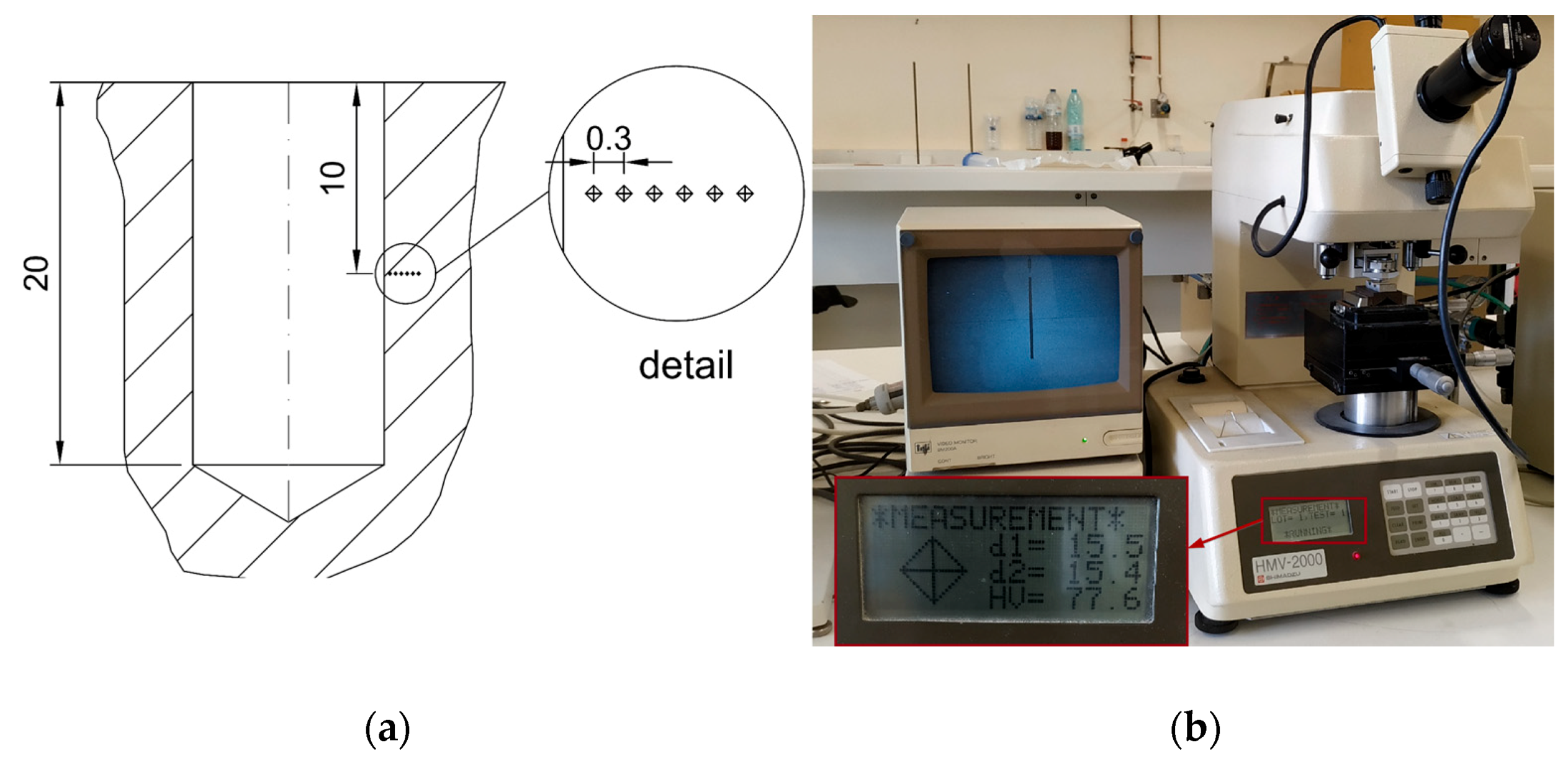
The Vickers microhardness measurement was performed using a Shimadzu HMV-2000 (Shimadzu Corporation, Kioto, Japan) microhardness tester, using a load of 10 g, on the previously sectioned holes. For this, successive measurements were taken in the middle of the depth of the hole in the radial direction, spacing them 0.3 mm from the machined surface, as shown in
Figure 5. Grinding and polishing operations were carried out in a metallographic polishing machine to prepare the test surface, using lubrication in the process and, subsequently, removing residues using an ultrasonic cleaner and subsequent cleaning with ethyl alcohol.
To carry out the design of the experiment, it started with the previous planning regarding the factors and their levels, as well as the quantitative response variables to be studied, considering the objective pursued, in addition to the available resources. The main response variable is the surface quality obtained in the drilling process, quantified by Ra, Rz and RSm, and to complement these data, the Vickers microhardness obtained at different distances from the machined surface and the height of the burr obtained was measured. The microscopic images of the surface will help to interpret the results acquired in the knowledge of the studied process.
The experimental design established was a full factorial design of three factors and two levels, and a factor with three levels, in addition to a two-level block established to consider the area in which the roughness was from the top face of the specimen, representing a total of 48 individual trials which were randomized. The factors to be considered in the present study, as well as the assigned levels, are those shown in
Table 2.
Due to results obtained in previous works in these types of operations and materials, in which the roughness measurements did not present normal distributions [
3], a study of the obtained data was carried out to verify their normality. For this, the Anderson–Darling and Kolmogorov–Smirnov tests were used, before performing the data analysis, which used the ANOVA method, allowing us to determinate what factors influenced the response variable and how they did it, for which the statistical software Minitab was used.
3. Results
After performing the individual drilling tests, the surface quality of the machined surface in each one was measured, at two distances from the top face of the specimen and at four points spaced 90°, for which it was quantified using the parameters of
Ra,
Rz and
RSm, considering the average obtained from the four measured points. The average results obtained for each of the individual tests, as well as the factors used in each of them are reflected in
Table 3. Note that the type of lubrication is not randomized. This decision was made because it was almost impossible to completely clean the lubricant residues from the specimen, as well as the tools under the test conditions, which could significantly affect the results obtained.
First of all, before performing the statistical analysis, the normality of the data obtained in the roughness evaluations will be studied. For this, the Anderson–Darling and Kolmogorov–Smirnov tests were used.
Table 4 shows the
p-values obtained in each of the two tests for the different parameters for measuring surface quality. This assumes normality of the data obtained from the measurements and it is possible to initiate their analysis using the ANOVA.
It is verified, in view of the results obtained, that the average
Ra measurements are below 2 µm and, therefore, the choice of the parameters of sampling length and evaluation length, previously established, is confirmed as correct. The minimum value was obtained for a combination of factors of drill point angle of 118° and TiN coating, and a feed rate of 0.4 mm/rev without lubrication in the top measurement height, being the value of 0.55 µm. Regarding each of the four measurements made at two heights from the upper surface in every individual hole, the
Ra values vary from 0.3 µm for the smallest to 1.66 µm for the greatest. This assumes that not all the values are within the range required as a general rule, which for the aeronautical sector would be between 0.8 and 1.6 µm [
39,
40]. However, taking into account the 16% rule established in ISO 4288:1996 standard [
35], the surface roughness would be considered acceptable, since only 2.1% of measurements would exceed the upper limit.
The statistical analysis of the results obtained from the
Ra measurements using the ANOVA is shown in
Table 5, which shows the reduced model for the factors and interactions that have significant influence, using a significance level
α = 0.05, following a step-by-step process of adding or removing terms at each step. The significant factors were, among the main ones, the type of coating
C, the point angle
γ, and the measurement depth,
MD; and among the first-order interactions were
C * L,
f * L and,
γ * L, following a decreasing order of their contribution.
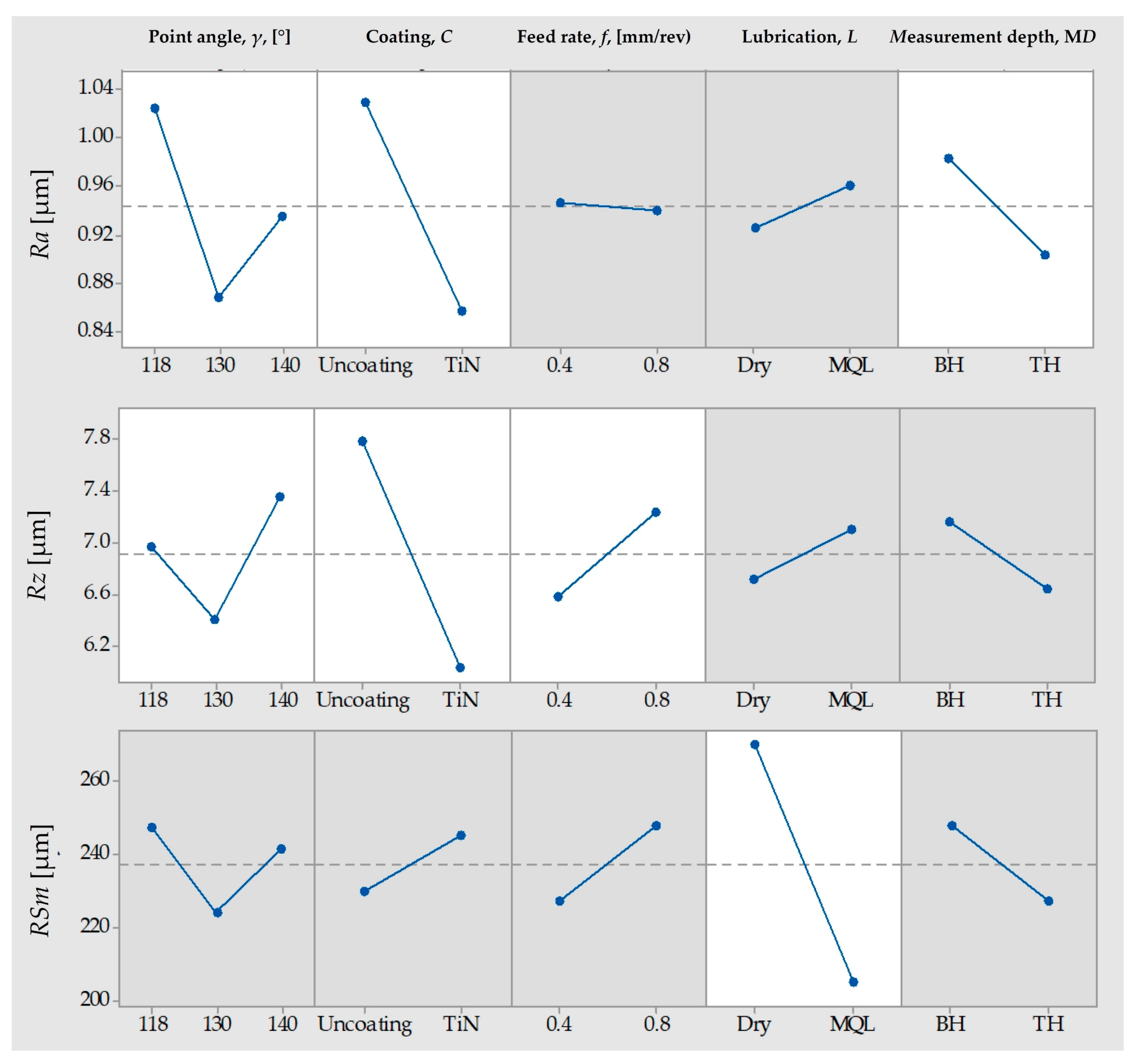
Considering the values of surface roughness measured on the machined surfaces, as can be seen in
Figure 6, the factor that has the greatest influence on roughness is the type of coating, reaching 39% of contribution. It shows the effects of the main factors and highlights the improvement obtained when tools with TiN coating are used, going from 1.03 to 0.86 µm in the
Ra values and from 7.78 to 6.03 µm in the
Rz. These results are consistent with previous work for this type of operation and material specifically [
3], as well as what is expected for drilling operations in general [
27].
Regarding the drill point angle, the minimum roughness is obtained when its value is 130°, however, its behavior is different depending on the coating of the tool. When using uncoated drills, the response marks a minimum when using 130° angles; however, when using drills with TiN coating, the response is practically linear, reducing the roughness obtained by increasing the point angle used in the tool, as reflected in
Figure 7. This result is important, since it is possible to optimize the drill point angle in the sharpening operation, depending on the other machining parameters, since, as evidenced, it is different for the diverse conditions used.
The depth of measurement from the surface is the other main factor influencing the
Ra. The lower
Ra values were obtained on the area closest to the top face of the specimen. The explanation for this behavior would be that as the drilling process deepens, it becomes more severe, due to the greater difficulty of evacuating the chips, the lesser evacuation of the heat generated and, in case the MQL lubrication system is used, the greater difficulty that the lubricant acts on the cutting area. This influence was found in previous works by Berzosa et al. [
3], but this effect was not significant.
With regard to first-order interactions, lubrication appears in the three that are significant with; the coating,
C * L, the feed rate,
f * L and, the point angle,
γ * L, ordered according to their contribution, as shown
Figure 8. The most important is
C * L, in which it is verified that when machining under dry conditions, the use of TiN coated drills significantly reduces roughness; however, when using MQL lubrication, this decrease is much less. One explanation would be that the lubricating effect of the MQL system would be of great importance in uncoated bits, whose coefficient of friction is greater, being the effect less in drills with TiN coating, in addition, as can be seen in
Figure 9, the use of this type of lubrication allows the small chips or particles produced to agglomerate during machining, which would increase the adhesive effect on the tool and/or surface of the specimen during machining, a point to be discussed later.
The roughness parameters that were considered to complete the roughness analysis were
Rz and
RSm, which were analyzed in the same way used for
Ra, and whose results for the main effects can be seen in
Figure 5. The graphs, and therefore the effects, of the different factors regarding their influence on
Rz and
Ra are practically the same, except for the case of feed rate, which had almost no influence on the measured
Ra values and was not significant and, in the case of
Rz, it is significant and, unlike
Ra, increasing the feed rates increases the measured
Rz values, as shown in the
Figure 5. Therefore, a greater feed rate has produced an increase in the peak valley distance in each of the sampling distances that are 0.8 mm, which is in the order of magnitude of the feed rate and, at the same time, has not significantly changed the average distance of heights. In the frame of this study, this is part repair tasks, and in order to increase the life of the component, the parameter with the most significance in terms of fatigue resistance would be the
Rz [
34,
41], and therefore, the smallest feed rate of the range considered should be used, that is 0.4 mm/rev.
The type of lubrication is the only significant effect in terms of its influence on RSm. The use of MQL lubrication significantly reduces the measures RSm values, reducing its value when using MQL lubrication, compared to dry drilling, which means that the average width of the roughness profile decreases.
This reduced model for
Ra has a parameter of
R2 = 57.89%, being for
Rz of
R2 = 72.85%; even better, it is a weak model to explain the total variability obtained in the measurements, which reinforces the need to complement the analysis with new variables, which also occurred in previous similar works [
3,
10] and determined the need for complementary analyses. Thus, the microscopic study of the drilled surfaces will be carried out, which will help in the qualitative evaluation of the textures on the drilled surfaces.
Holes were selected to make a longitudinal cut of the specimen to examine the characteristics of the machined surface by microscopy. For it, the main factors with significant effects on the
Ra were taken into account; these are, type of coating and point angle, as well as the feed rate as it was significant on the
Rz. The holes selected for the analysis were those which extreme values of roughness were obtained. The values of the parameters used are shown in
Table 6.
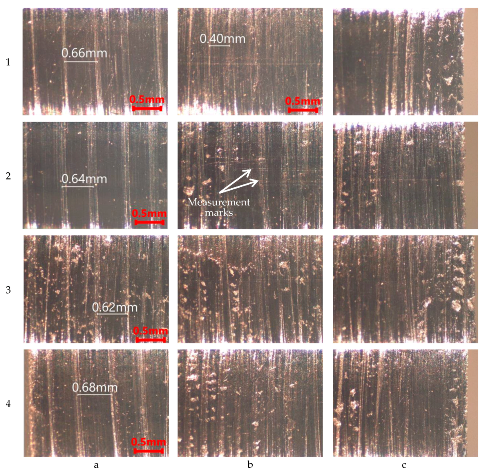
From the microscopic images obtained from the surfaces of the sectioned holes, it appears that three areas can be clearly characterized. The first area, zone a, would be the one with the greatest depth of the hole corresponding to bottom zone, in which inclined marks are clearly distinguished as can be seen in images 1a, 2a, 3a and 4a of
Figure 10, which are the result of the drill’s back movement. This statement is based, on the one hand, on the marks direction, which is compatible with the backward movement of the tool and, on the other hand, on the fact that the period does not coincide with the feed rate established in machining, but would be the maximum feed rate of the machine, which is the one used in the return movement of the tool in the CNC drilling cycle. Furthermore, spacing is similar regardless of other parameters, including feed rate.
Zone b corresponds to the middle part of the hole, in which the marks in the reverse direction overlap with those of the forward direction. In addition, the marks in the direction of feed rate have a spacing of 0.41 mm, as shown in image 1b of
Figure 10, which coincides with the feed rate of 0.4 mm/rev, which corroborates the statement. The measurements of the distance between the marks are indicated in white, while the scale of the images appears in red in the lower right corner. Zone c is the zone near the upper surface, in which the marks of the feed rate predominate and where large marks can be observed, phenomena that will be called pitting.
A direct relationship between the obtained roughness values and the optical characterization of the surface is presented. Pitting appears, to a lesser extent, on the deepest area of the hole, increasing its number and size as the area studied approaches the surface of the specimen. Comparing holes 1 and 2 that used a drill with point angle of 130° and TiN coating, with holes 3 and 4 that used a drill with a point angle of 118° without coating, it is seen that there is a significant increase in the number and size of pitting consistent with the increase in the surface roughness pointed out previously, so that the results are compatible with the statement that the surface roughness is negatively affected by pitting on the surface.
It can be seen in the images of
Figure 10, horizontal lines appear in zones b and c, for example in image 2b. These marks are due to the roughness measurement process in which the probe traverses the surface in that direction. In zone a, they do not appear since roughness was not measured at that depth because it did not reach it with the length of the probe arm.
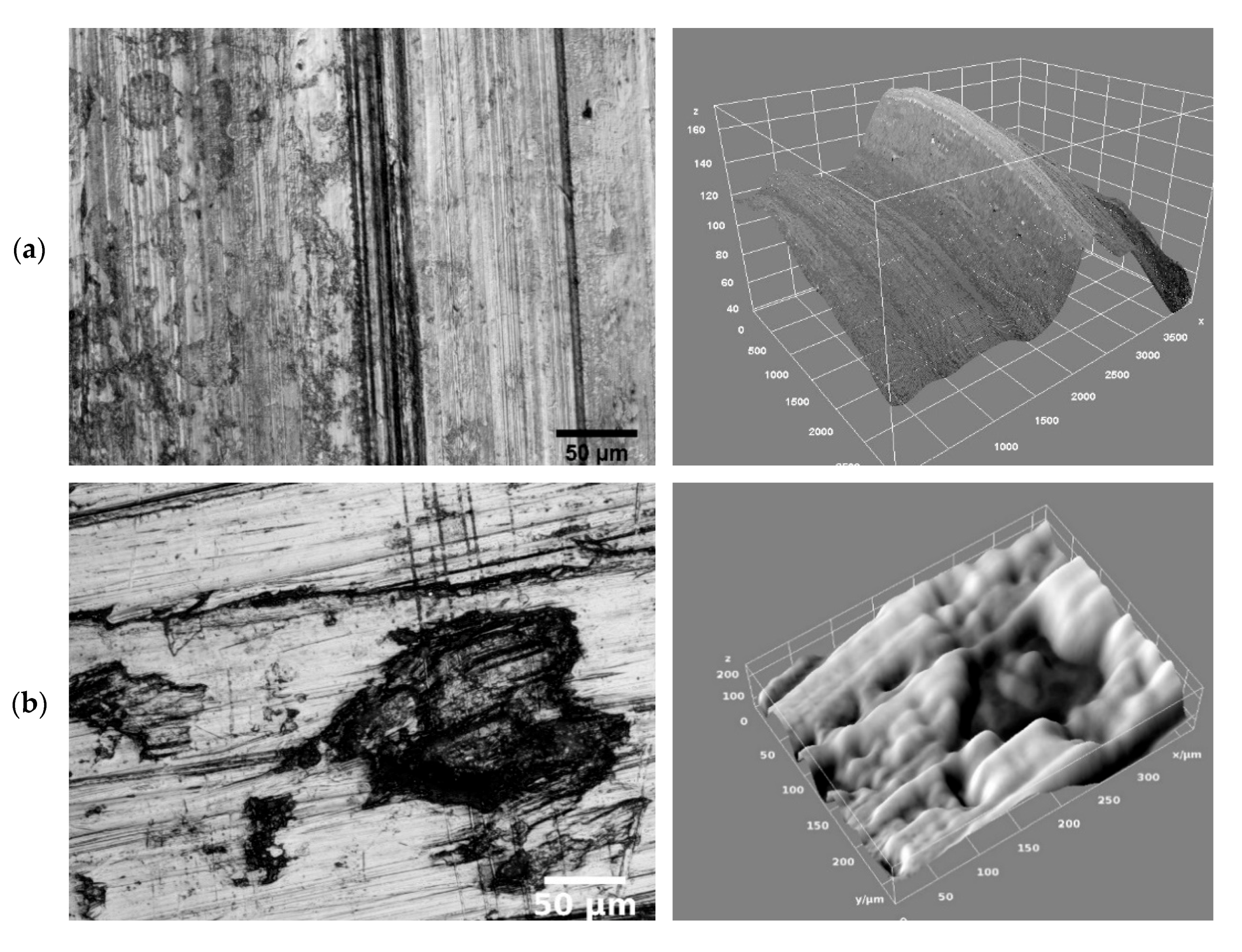
The Interactive 3D Surface plot plugin [
42] was used to create a 3D image, which shows a topological reconstruction from a set of images, using the EDF technique to study the surface texture. As shown in
Figure 11a on right, it is corroborated that the surface marks in the backward direction of the tool, are shown as peaks, which means that the process is not material removal, but material deposition. The explanation could be the high tendency of magnesium to form adhesions on the tool, which appeared in previous works [
10], and that in the backward movement it would scratch and deposit on the previously machined surface.
Likewise, it is confirmed that pitting is shown as valleys, as can be seen in
Figure 11b on the right. An explanation of these pittings would be related to the small chips or particles, which are shown in
Figure 10, that were formed in the magnesium alloys at particular cutting conditions, which would be trapped between the machined surface and the exterior of the drill, deforming and producing contact stresses that would cause particles to detach from the surface. As a result, pitting can be observed. Further tests were to be carried out to confirm this hypothesis.
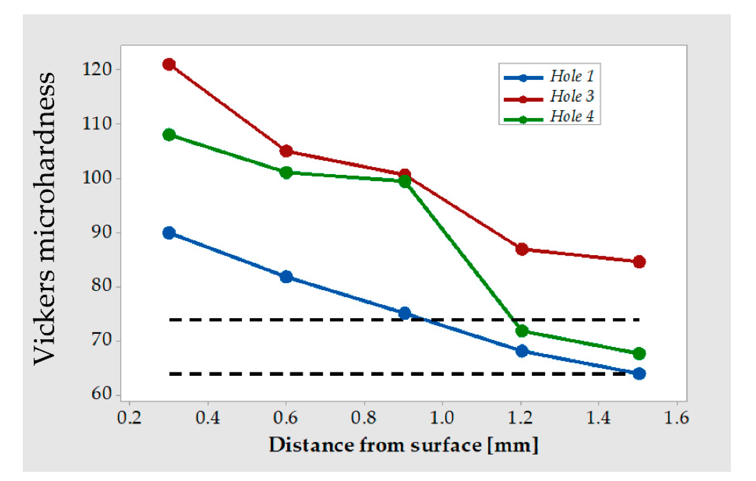
The Vickers hardness of the raw material was measured in areas sufficiently far from the machined holes, fluctuating the values between 64 and 75 HV. In addition, hardness measurement was performed at various distances from the machined surface, using the previously sectioned holes to obtain the metallographic images. The variations in the obtained hardness values are justified by the different phases presented in the alloy [
18].
Figure 12 shows the decrease in surface microhardness as the distance from the surface increases, reaching the values close to the initial of the alloy around 1.5 mm from the machined surface. The increase in hardness is related to the parameters used. The use of a drill with a point angle of 130° and TiN coating have lower increases in hardness than using drill with a point angle of 118° and without coating. These results are similar to the improvement in surface quality. It can be postulated that the increase in hardness values has been due to deformation hardening phenomena. In addition, under the more severe machining conditions, an increase in surface hardness occurs and, at the same time, an increase of roughness.
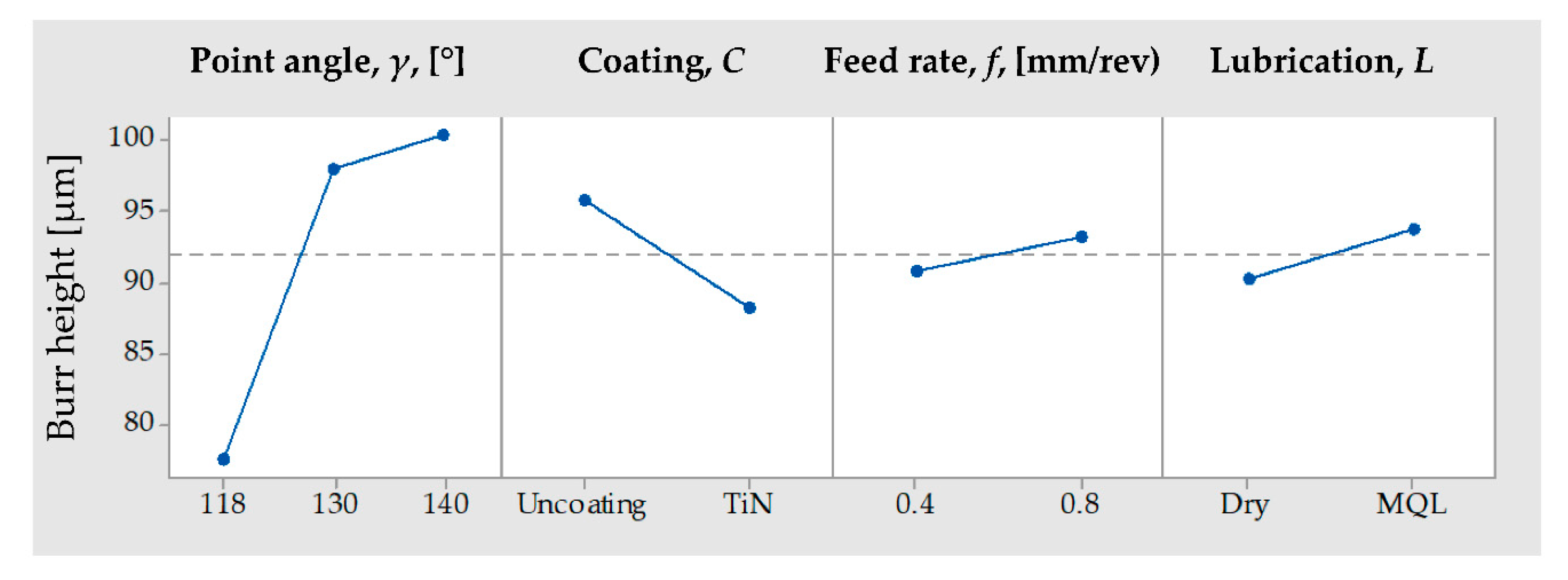
Regarding the burr height measurements, the influence of the main parameters used on the average value at the four points spaced 90°, at which it was measured on the drill entrance surface, are shown in
Figure 13, corresponding to a non-reduced model. The point angle of the drill and the type of coating are the most important factors in terms of the average height of the entrance burr obtained in the drilling process. In addition, the analysis of the maximum value of the height of the burr in these four points was carried out, obtaining results and conclusions similar to those indicated above.
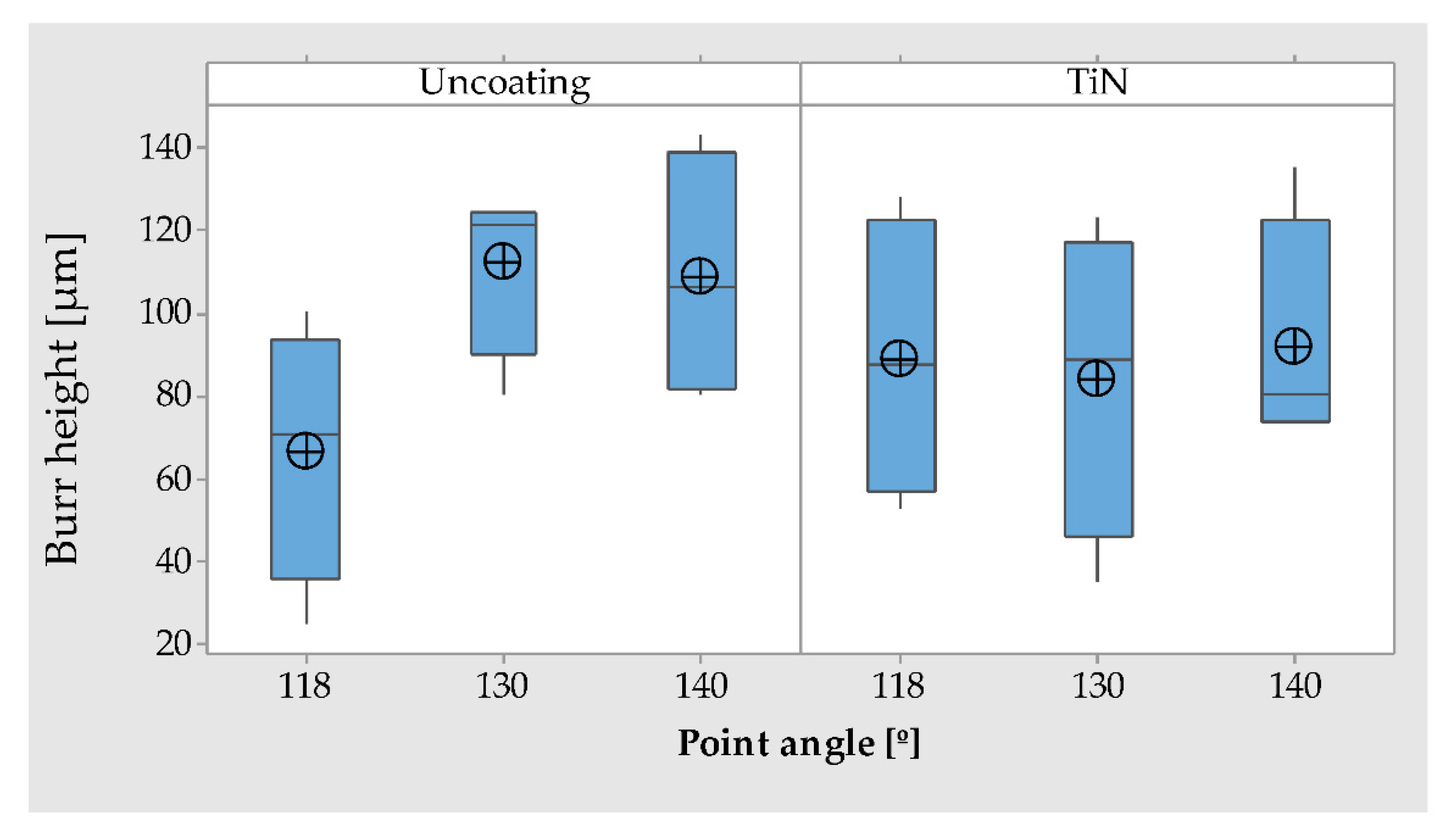
Reducing the height of the burr was achieved using smaller point angles, decreasing the average height from 100 µm using a point angle of 140° to 77.5 µm when it is 118°. Similarly, a reduction was achieved when using TiN coated drills, going from 96 to 88 µm. Deepening the results obtained, when uncoated drills were used, the use of a point angle of 118°, results in a considerable decrease in the height of the burr close to 50% and, being practically insignificant the difference between the different values of the point angle when using TiN coated drills, as can be seen in
Figure 14.
For a more complete knowledge of the re-drilling process, it would have been helpful to carry out measurements of the forces that appear in machining, specifically the feed force and torque. These measurements could not be performed at the time of the experimental study in this investigation. However, it is possible to obtain some interesting data to aid in the knowledge based on previous work about drilling of similar magnesium alloys. Bhowmick et al. [
14], studied the feed force and torque in drilling operations in the AM60 alloy with 6.35 mm diameter drills, using dry and MQL as a lubrication-cooling system, obtaining similar values of average torque in the first drills, around 2 N-m and feed forces very close to 100 N, and that these values under these conditions remained constant during the drilling operation. In a similar work, Bhowmick and Alphas [
16], carried out the study of the torque in drilling operations in the AZ91 alloy using uncoated HSS drills and coated with diamond-like carbon, with a diameter of 6.35 mm, obtaining torque values in the first holes between 1 and 3 N m under the conditions tested. Weiner et al. [
12], studied the efforts in the drilling of magnesium alloys AZ91HP using different types of drills of diameter 14.5 mm, using values of high performance, specifically cutting speeds of 500 m/min and feed rates of up to 1.2 mm/rev, obtaining values increasing with feed rate, the torque between 5 and 20 N-m and the feed forces between 0.5 and 1.5 kN.
Considering the above and taking into account that the conditions of the re-drilling operations were carried out with drills of 8 mm diameter with a depth of cut of 0.125 mm, it is presumable that the values of the feed forces and the torque were maintained at values relatively low and therefore the said phenomena would have a contained influence on the process itself and on the surface quality obtained on the machined surfaces. However, it is not possible to rule out a greater influence, which is why the need to carry out subsequent tests to confirm the hypothesis is evident.


