Article

Structural, Fatigue Behavior, and Mechanical Properties of Zirconium Tungstate-Reinforced Casted A356 Aluminum Alloy

1
Department of Metallurgy and Materials Engineering, University of Engineering and Technology, Taxila 47050, Pakistan
2
Department of Mechanical Engineering, College of Engineering, Prince Sattam bin Abdul aziz University, AlKharj 11942, Saudi Arabia
3
Physics Department, College of Science, Jouf University, Al-Jouf, Sakaka 2014, Saudi Arabia
4
School of Chemical and Materials Engineering, National University of Sciences and Technology (NUST), Islamabad 44000, Pakistan
5
Department of Mechanical Engineering, Institute of Space Technology, Islamabad 44000, Pakistan
*
Author to whom correspondence should be addressed.
Metals 2020, 10(11), 1492; https://doi.org/10.3390/met10111492
Submission received: 28 September 2020 / Revised: 30 October 2020 / Accepted: 2 November 2020 / Published: 9 November 2020
(This article belongs to the Section Metal Casting, Forming and Heat Treatment)

Abstract

:
The aim of this study is to investigate the structure–property relationship of the zirconium tungstate-reinforced casted A356 aluminum alloy. The reinforcement ceramic used was zirconium tungstate of the negative thermal coefficient type, which assists in the weldment of crack growth and enhances the fatigue life. The specimens used in this study were casted by stir casting method and prepared according to Compact Tension standard E-399, and microstructural, fatigue behavior, and mechanical properties were investigated systematically. Microstructural analysis showed reduction in porosity by the addition of ZrW2O8 particles. Fatigue results depict the increase in the fatigue life of aluminum reinforced ceramic as compared to the casted base aluminum alloy. Brinell hardness of ZrW2O8 reinforced alloy samples increased 7% as compared to the base aluminum alloy hardness value. Tensile strength also significantly improved from 176 MPa for the base A356 alloy to 198 MPa for the ZrW2O8 reinforced composite. Furthermore, addition of ZrW2O8 ceramic powder increased the fatigue life more than 50% of the base alloy. These results suggest that the ZrW2O8 reinforced A356 composites may be potential candidates for aerospace industry, military, transportation and in structural sites.

1. Introduction

During the last two decades, a lot of research has been done on Metal Matrix composite (MMC) for improvement in the industrial sector. The combination of high strength, high modulus refractory particles with a ductile metal as a matrix produces a material whose mechanical properties are in between ceramic particle and metal matrix. MMC are being used for the structural applications of transport and aeronautical sector, due to their enhanced mechanical and thermo physical properties. Aluminum matrix composite (AMC) is one the most prominent MMC, as they are cheap and easily available alloy. Certain AMC properties like long fatigue life, high specific modulus and corrosion resistance made this material especially prominent in field of aerospace, automobile, transportation, and building industries. Different techniques were used for the preparation of AMC. One of the cheap and simple technique is stir casting method [1,2,3,4,5,6,7]. The high strength-to-weight ratio and excellent properties like Al-Si mixture replaced the steel and cast iron from different fields [8,9].
In most cases, aluminum-made machineries deteriorated due to fatigue loading. Researchers have proposed different techniques to solve this matter and to improve the fatigue life and mechanical properties of the aluminum alloy. It was concluded that the existence of second phase particles have positive effect on the fatigue behavior of aluminum alloy matrix. At high temperatures, these particles can be used as precipitate. Mostly particles were composed of Zr, Cr, and Mn. Second phase particles are hard enough which promote planar slip, and also affect crack branching, crack closure, crack deflection to decrease the possibility of fatigue crack growth (FCG) [10]. Elhadari et al. [11] added thermally stable alloying elements: Zr, V, Ti in the aluminum alloy to improve the fatigue life and tensile properties. Silicon carbide (SiC) is one of the mostly used ceramic for the preparation of aluminum composite. SiC particulate enhanced the fatigue life of spray formed aluminum alloy. AMC formed with the SiC particles improved the tensile and yield strength. Fatigue strength and fracture behavior of the matrix was also enhanced [12,13]. Lisa Winter et al. [14] observed the effect if SiC on the fatigue behavior and mechanical properties of 2124 Al alloy. Fatigue and mechanical properties increase with the addition of ceramic particle. Squeeze casted aluminum alloy was aged after the heating process. The fatigue life of aged alloy was increased, after it was tested. Other mechanical properties also shown an improvement in the result [15,16].
Sajjadi et al. [17] formed aluminum matrix composite with the alumina particles, it enhances the mechanical properties of aluminum alloy. Different processing techniques were used for the preparation of alumina reinforced aluminum matrix. Zhu et al. [18] enhanced the fatigue behavior of aluminum matrix with the addition of aluminum borate whiskers, this addition of whiskers was experimented with the method of squeeze casting. J. Jeykrishnan et al. [19] enhances the mechanical properties (hardness, tensile, and impact) of aluminum alloy by addition of titanium di-borate as a reinforcement. Hai Fu et al. [20] enhances the fatigue behavior with the inclusion of ceramic particles. Zirconia oxide was used as biomaterial with unique qualities like transformation toughening which gives it toughness and high strength as compared to other ceramics. It is thermally stable compound with good quality of corrosion resistance and mechanical properties. Zirconia oxide and coconut shell were used as reinforcement for the improvement mechanical properties of aluminum alloy. It enhances the tensile, hardness and impact strength of the alloy [21]. D. Mummoorthi et al. [22] added Fe2O3 and B4C as a reinforcement to enhance the tensile and hardness properties of the aluminum alloy. R. Pandiyarajan et al. [23] enhances the mechanical properties of aluminum by addition of Zirconium oxide and graphite. Madhusudan et al. [24] used copper particles for the preparation of aluminum matrix composite. It helps in the enhancement of the strength and hardness of the composite.
A unique type of material has been introduced which contracts upon heating and expand during cooling. Negative thermal expansion (NTE) materials have extraordinarily industrial advantages to control the thermal expansion of different materials. This concept has been introduced in the composite to control the thermal expansion. The NTE build composite will generate new functionalities like light weight, high strength structural material, low expansion, and large scale. High-precision equipment with ultimate thermal expansion control can be built with this concept. Zirconium tungstate (ZrW2O8) is one of the types of NTE, having good qualities as compared to other NTE materials. ZrW2O8 has unique properties of negative thermal coefficient; it gets contract upon heating and expand upon cooling. These properties are considered to be helpful in the crack weldment and crack closure, causes due to the fatigue loading. When crack initiate in the fatigue loading, the temperature of that area increases, so inclusion of these particles may contract the area of crack initiation and helps in crack closure and weldment. Furthermore, ZrW2O8 acts as hindrance in the path of crack opening and can improve the strength of the material. Consequently, mechanical properties of the alloy can be improved with the incorporation of these particles. Various types of composite can be build using (ZrW2O8) as a reinforcement. Some of the composites are ZrW2O8/aluminum, ZrW2O8/copper, ZrW2O8/phenolic resin, etc. [25,26].
On the contrary, A356 is one of the mostly used alloys due to its good silicon content. Silicon helps in fluidity of casting and is helpful in other mechanical properties. It has good resistance to corrosion and also imparts strength to other mechanical properties. Cu and Mg were added to Al-Si which also added their part in increasing the mechanical properties [27,28].
In this scenario, a novel AMC was developed in this study by using A356 as a base metal and ZrW2O8 as a reinforcement material and its structural, fatigue and mechanical properties were explored. The major aim of this work is to evaluate the fatigue and mechanical behavior of the A356 alloy with the combination of ceramic particles. According to best of our knowledge, the investigated matrix/reinforcement composite is not prepared and studied for mechanical properties.

2. Material Properties and Experimental Procedure

2.1. Sample Preparation

The material used in this research was A356 Al alloy, composition of the alloy is given in Table 1. The density of the Al alloy is 2.75 g/cm3. This alloy is reinforced with particles of ZrW2O8 of 1.86 microns in size; the chemical composition and properties of the ceramic are given in the Table 2. Stir casting, one of the low-cost casting techniques with various processing parameters, was used to disperse the ZrW2O8 particles into the melted A356 Al alloy and produce a composite. In a stationary port type pit furnace [29], cut ingots aluminum alloy were melted in a clay graphite crucible at a temperature of 750 °C.
After complete melting of Al alloy coverall flux and hexaflourine tablet was added to remove the dust particles from the molten metal and discharge the entrapped gasses from the molten metal respectively. The slag and dust particles were removed from the top of the crucible. The zirconium tungstate particles were pre-heated at 200 °C, in order to remove the moisture contents. The parameters of stirring setup were addition rate of ZrW2O8 in 4% amount, stirring speed of 600 rev/min and 5 min stirring time for uniform distribution. The melted composite was then poured into pre-heated permanent mold of 298 mm in length, 143 mm in width, and 10 in thickness and allowed to solidify at an atmospheric condition [30].
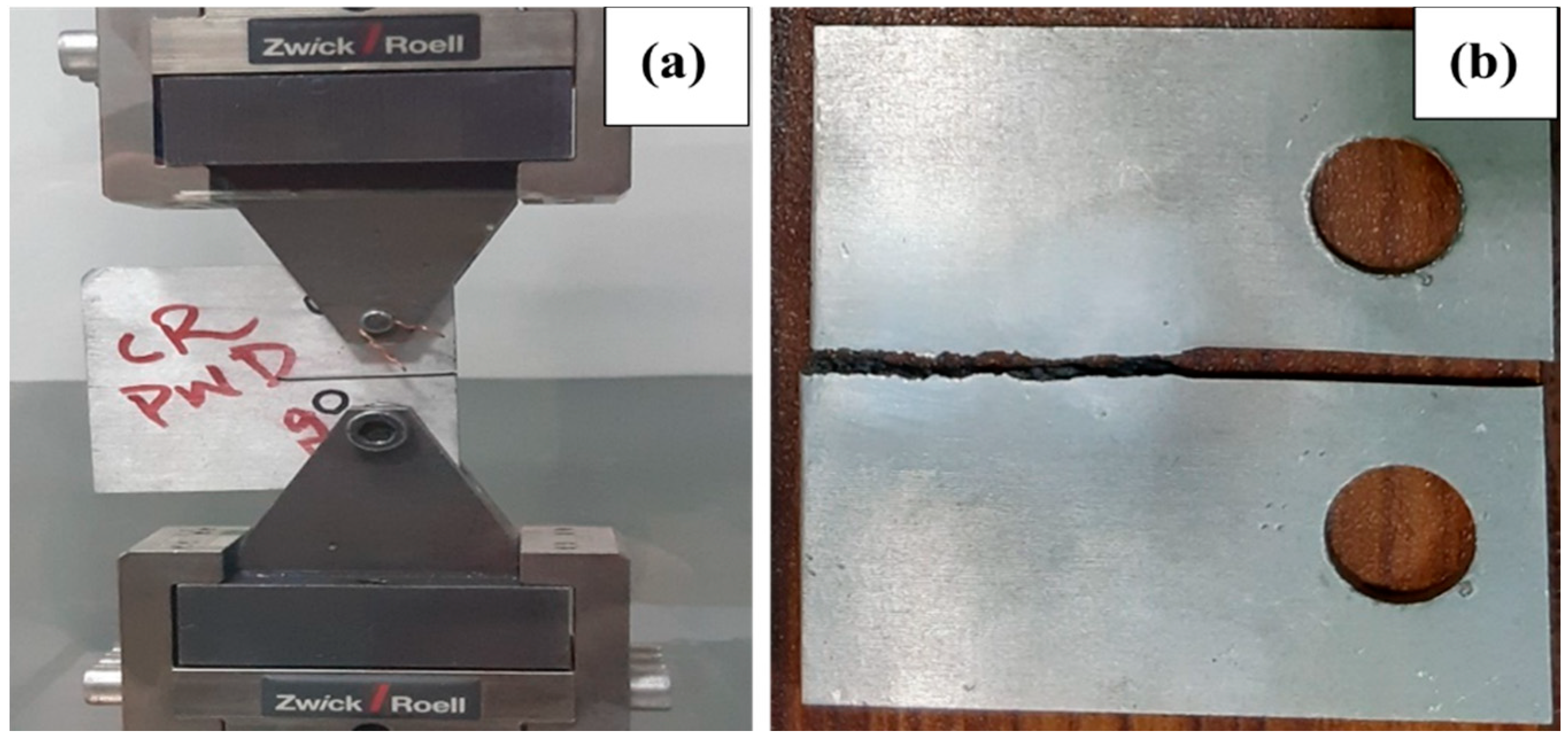
The casted samples were cut out into two pieces, as during one-time casting 2 samples were achieved. Samples were machined with the vertical milling machine according to the given parameters of standard ASTM. Two holes of 14 mm diameter were drilled on each of the samples by drilling procedure for gripping in the hydraulic machine (Zwick Roell, Ulm, Germany). Notch was formed with an Electric Discharge Machining (EDM, Neuar Precision Machinery Co. limited, Taipei, Taiwan) using copper electrode of designed notch prepared by wire cutting machine (Suzhou Baoma Numerical Control Equipment Co. Ltd., Jiangsu, China). The finally prepared samples are in the dimension of 71.5 mm × 68.6 mm × 6 mm as shown in Figure 1a. which is the ASTM standard for fatigue test also known as Compact Tension C(T) E-399 sample [31].

2.2. Experimental Techniques

2.2.1. Tensile Testing

Micro-tensile specimens of D1708 ASTM standard were prepared from the casted aluminum alloy to compare the tensile properties of composite and casted base alloy. Tensile tests were performed up to failure on the fully automatic, servo hydraulic machine of Shimadzu (Zwick Roell, Ulm, Germany) equipped with 100kN load. Figure 1b shows the break tensile sample. The strain rate value for the all the samples was 1 mm/min. The gauge length of the samples was 25 mm. All the tests were performed under the same constraints.

2.2.2. Hardness

The Brinell hardness test of the samples was performed on the Optical Hardness Tester (HBRVU-187.5, Time Group Inc. Beijing, China). The size of the indenter was 1.5 mm, the load applied on each sample was 980N, and the holding time for each load was 30 s. Total of 8 samples were tested, 4 of Al composite and 4 of base Al-Alloy. Average hardness value of samples was reported for result comparison.

2.2.3. Fatigue

The Compact Tension C(T) samples of ASTM E-399 standard were tested in a Servo Hydraulic Machine of Zwick Roell (HC-25, Zwick Roell, Ulm, Germany) under control load of tension–tension with stress ratio of 0.1 at a frequency of 10 HZ. All samples were tested at room temperature of 15 °C; the relative humidity was in the range of 20 to 35%. Samples were tested in the low cyclic fatigue mode (See Figure 2a). For Low Cycle Fatigue (LCF), the applied load value for fatigue testing is usually taken between the range of 50 to 80% of its tensile strength. As fatigue strength of any material is usually lower than its tensile strength. In this study, four different stress values of 40, 35, 30, and 25 MPa at load value of 80, 70, 60, and 50% of its tensile strength were applied, respectively. The crack initiation site (notch area) was polished with 900-grit emery paper to observe the crack initiation clearly. Four samples of each composite and base alloy were tested at four different values of stress amplitude (25, 30, 35, and 40 MPa). Samples were tested until failure (Figure 2b).

2.2.4. Characterization

The initial microstructure of as-received casted-machined A356 aluminum samples was characterized by metallurgical microscope after sample preparation and polishing. The sample preparation was followed by sampling with epoxy and resin in the round pipe piece, then ground the samples with the emery paper of (120–2000) grit, to remove the final scratches; samples were polished with the alumina paste in order to observe the grain structure clearly. The polished samples were then washed with the Keller Etchant (2 mL HF, 3 mL HCL, 5 mL HNO3 and 190 mL water) for 30 s to remove the dust particles from the surface [32]. The microstructural analysis of the samples was done at 25 μm and 100 μm with the optical microscope equipped with image analyzer.
Fracture samples of the fatigue tested samples were analyzed by scanning electron microscope (SEM, Vega Tescan, Brno, Czech Republic). Sample pieces were cut on hacksaw, approximately 7 mm from the fracture surface. Samples were then washed with ethanol to remove the dust and foreign particles and mounted on the stubs for SEM analysis. Fracture analysis was done on the VEGA TESCAN SEM at 20 kV in scattered electron (SE, Vega Tescan, Brno, Czech Republic) mode and also in back scattered mode (BSE, Vega Tescan, Brno, Czech Republic) for phase contrast of the regions. Energy dispersive X-ray spectroscopy (EDS, Vega Tescan, Brno, Czech Republic) technique of SEM was used for the composition analysis of the samples.

3. Results and Discussion

3.1. Fractography

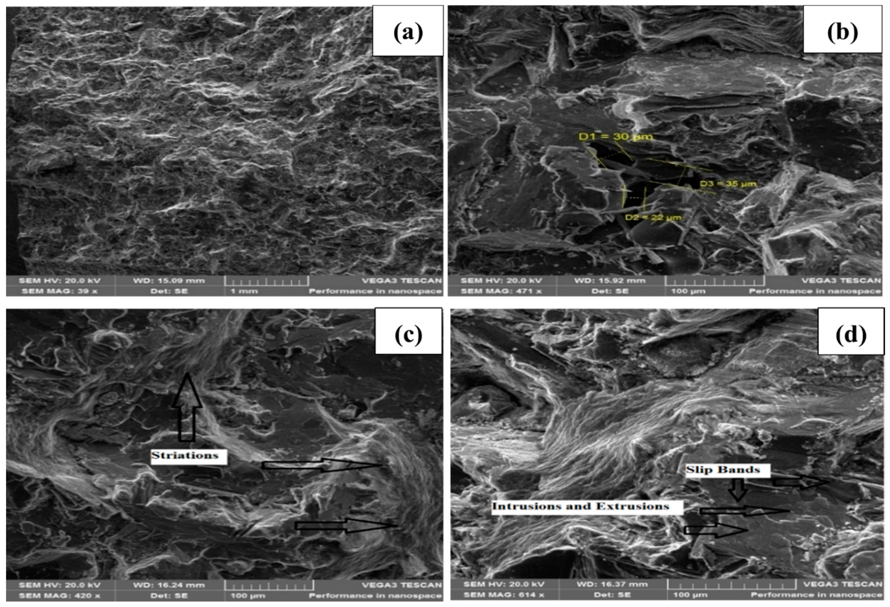
Figure 3 shows the SEM image of the fatigue break surface of base aluminum alloy. The fracture sample was analyzed at high magnification of the overall crack region. Figure 3a shows the overall crack region of base alloy with different planes. Figure 3b was observed at high resolution, which shows the pores with their dimensions and different ups and down regions. Figure 3c shows the river ridges of the crack surface. River ridges explain the crack propagation manner of the fatigue crack [33]. Fatigue crack striations and river ridges were observed in most of the images, which indicates that the samples were ductile in nature. It was also observed that most of the fatigue crack generated due the defects and porosity area of the samples [12]. Therefore, the porosity was the fatigue crack domination site. However, in the defect less sample, the crack propagation is due to slip bands and eutectic structure. In the region of early microscopic crack growth fine and shallow striations were found. It was found that the presence of hard particles in the soft area stops the formation of voids and keeps on the cyclic stressing of the material. Presence of Dimples indicate that there is formation of fine particles due to the addition of the ceramic particles [14]. According to previous studies, river-like ridges were observed in A356 material during the crack initiation process of tension loading, which depicts the ductile nature of the material [29,33]. The striations in the Figure 3c show that sample was ductile in nature. Fatigue loading also causes fracture surface with slip bands (see Figure 3d). Slip bands leads to the formation of intrusions and extrusions.
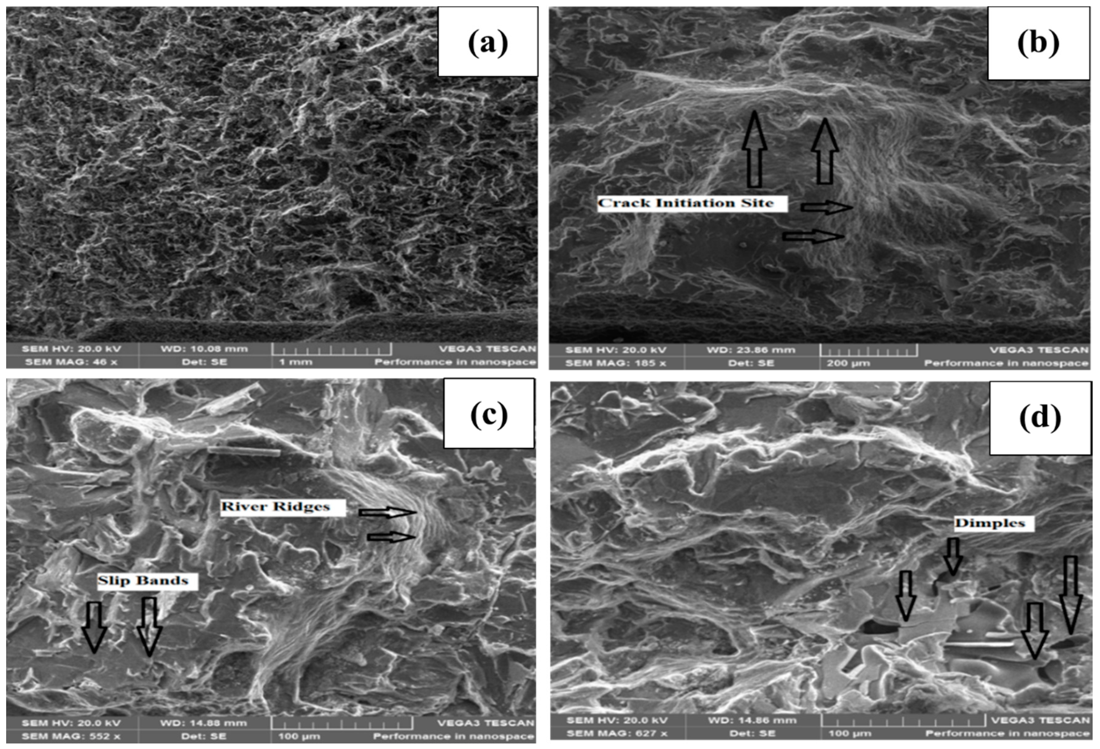
Micro-cracks mostly initiate from the intrusions. Therefore, slip bands has a main role in the initiation of fatigue cracks [34]. As it was discussed earlier, the eutectic Si particles have a long and elongated microstructure, which causes early breaking and crack initiation of the samples. In the initial period of low cycle fatigue loading, particle cracking occurs. When Si particles crack, it will become nucleation site for other micro-cracks [11]. In this manner micro-cracks increases with increasing fatigue cycle. Micro-cracks from all the region get combine and causes for the fracture of the samples. Therefore, it is analyzed in most of the cases that fatigue cracks mostly occur due to the breakage of silicon particles or the porosity of the region. But in the case of composite, it was observed that the ceramic particles hinder in front of crack propagation site and increases the fatigue performance of the sample [35]. Figure 4 shows SEM image of the crack surface of the composite. Figure 4a is the overall image of the composite fracture area which shows the different regions. Figure 4b is the crack initiation and propagation region of the composite. The presence of striation and river like ridges is the indication of the stable crack growth in the fracture surface [35] (Figure 4c). Fatigue striations and river ridges mostly occur due to the dislocation slips of the planes in the plastic zone region of the crack tip. Crack propagation rate slows down with the presence of reinforcement particles and are justified by the presence of dimples (see Figure 4d). The microscopic dimples of fracture analysis describe that the fracture is ductile in nature [21]. From the SEM micrographs, it was also found that one of the key reasons for crack initiation was larger defects near the sample surface, such as large pores, large shrinkages, which cause fatigue cracks.

3.2. Microstructure Analysis

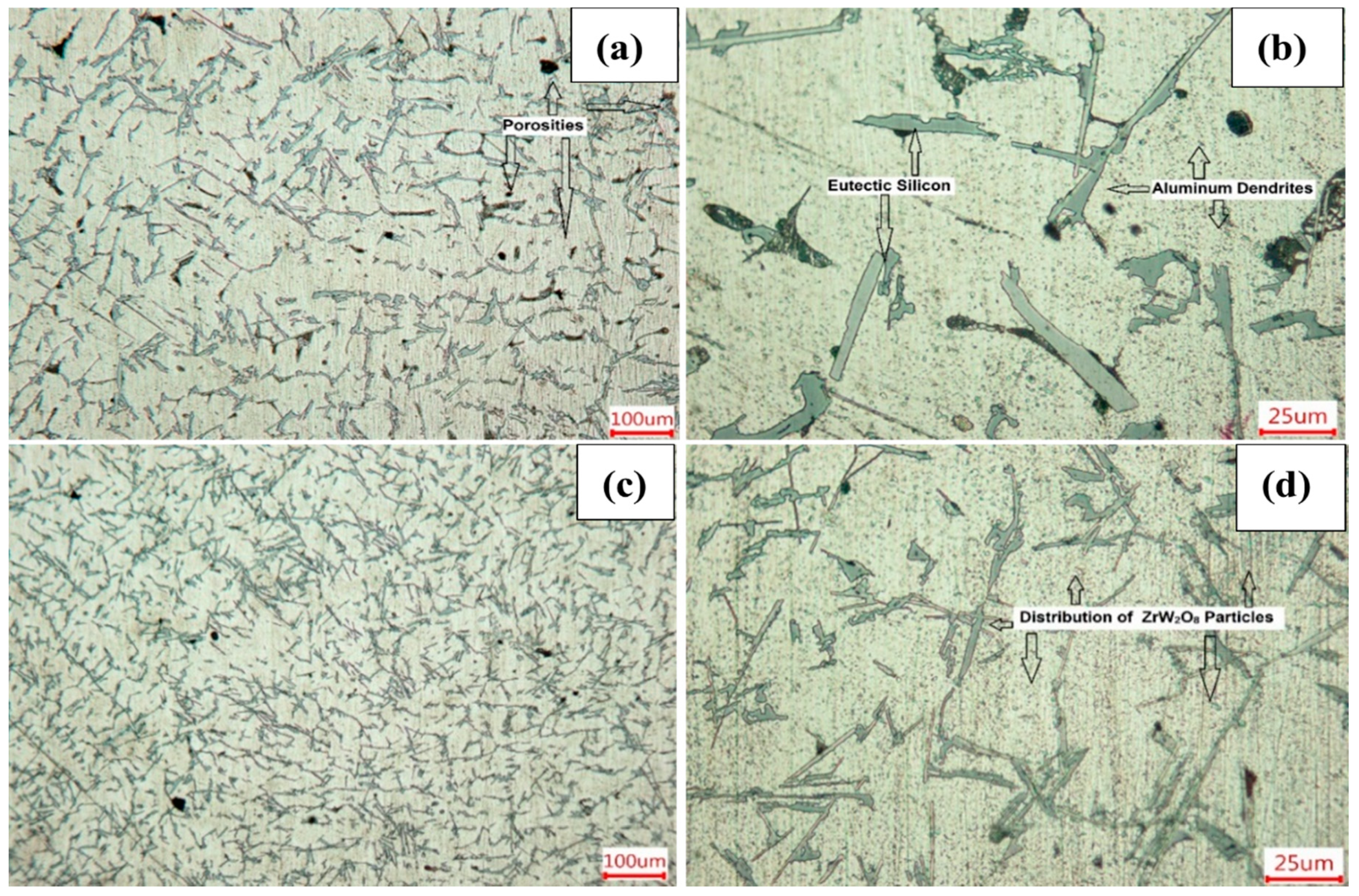
Microstructure of simply casted base aluminum alloy and ceramic reinforced Al-alloy is shown in the Figure 5. Porosity and shrinkage pores were also observed in the material because of ineffective feeding and cooling rate during the casting (Figure 5a).
The bright region in the figure depicts Al-dendrite structure and the dark gray regions are the eutectic Al-Si dendrite structures (Figure 5b). The cell-shaped Al-dendrites are the secondary dendrite cells. The characteristics of the eutectic Al-Si dendrite phase are three-dimensional in nature. The fatigue crack propagation path faces the Al-Si eutectic structures. Eutectic silicon particles were more sensitive to damage during cyclic loading. It was noticed that with the addition of ceramic particles, the number of pores decreased in Al-composite as compared to the base alloy which does not have ceramic inclusion (Figure 5c) [36]. It was also observed from the Figure 5d that increasing cooling rate refines the eutectic particles and also changes their morphology from large plates to long fibers. With the addition ZrW2O8 ceramic powder, the eutectic structure of Al-Si structure becomes more refined [37]. It may be due to increased solidification distance which solidify the melt slowly and particles become coarser and elongated. However, it has also some disadvantage too, as there are more chances of cracking of large elongated particles [35]. The amount of Mg content has a main role in the particle cracking because of the enlarged size of eutectic Al-Si and Fe rich intermetallic particles [34]. Figure 5d shows the dispersion of ZrW2O8 ceramic particles in the aluminum matrix [22]. The particle size of the ceramic was 1.86 μm.
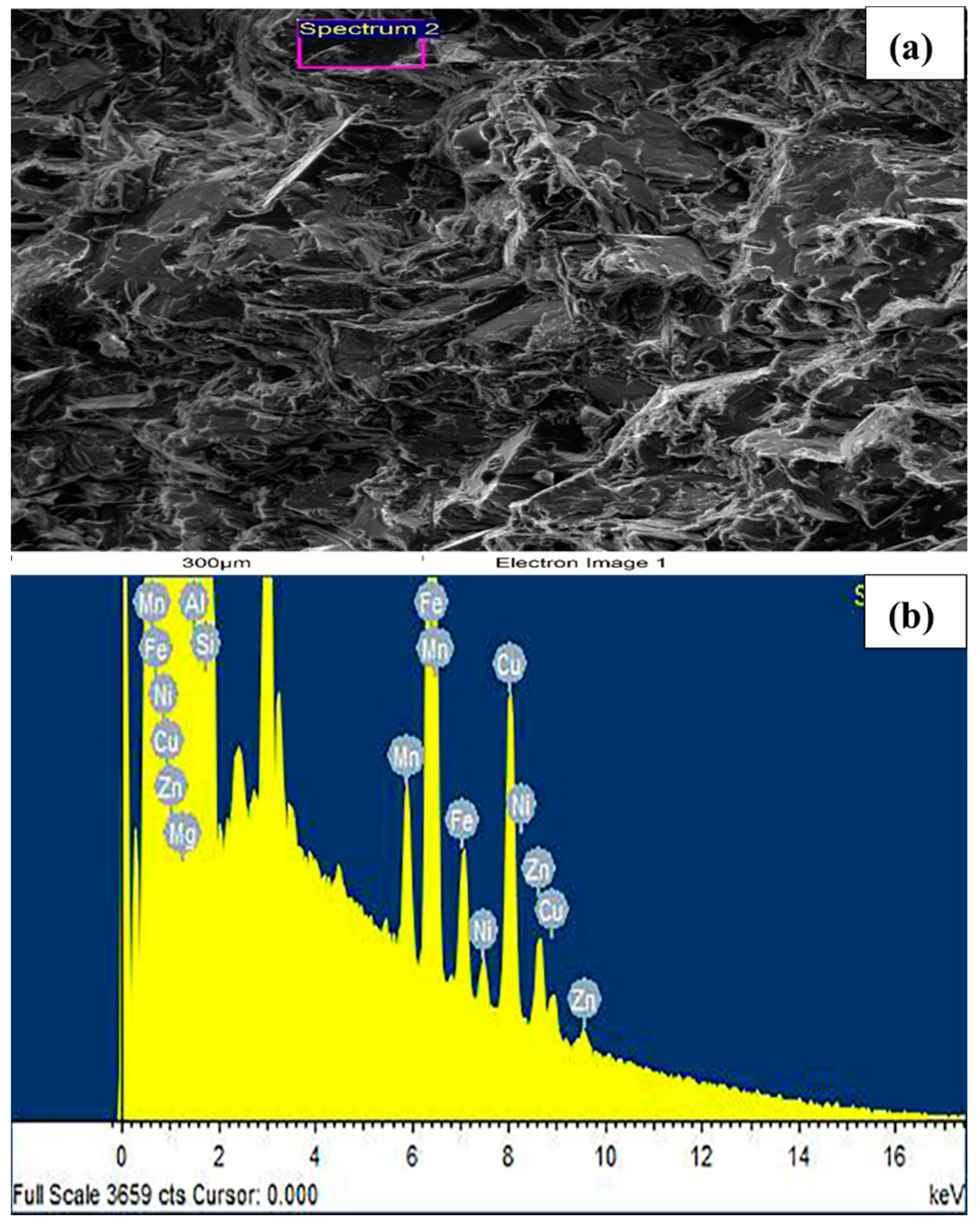
Figure 6 shows the SEM micrographs with the support of an EDS line scan of different phases present in the base alloy. The EDS results of the base Al-alloy only consist of the A356 alloy elements; the presence of copper in the Al-Si alloy gives it strength through the formation of Al2Cu and also with the combination of Al-Fe-Si structures. Magnesium also has its own role in the matrix. It forms a structure Mg2Si and strengthens the overall alloy. Iron can be easily chosen during the melting of aluminum and inevitably present in cast aluminum-silicon alloy [11] (see Figure 6a,b).
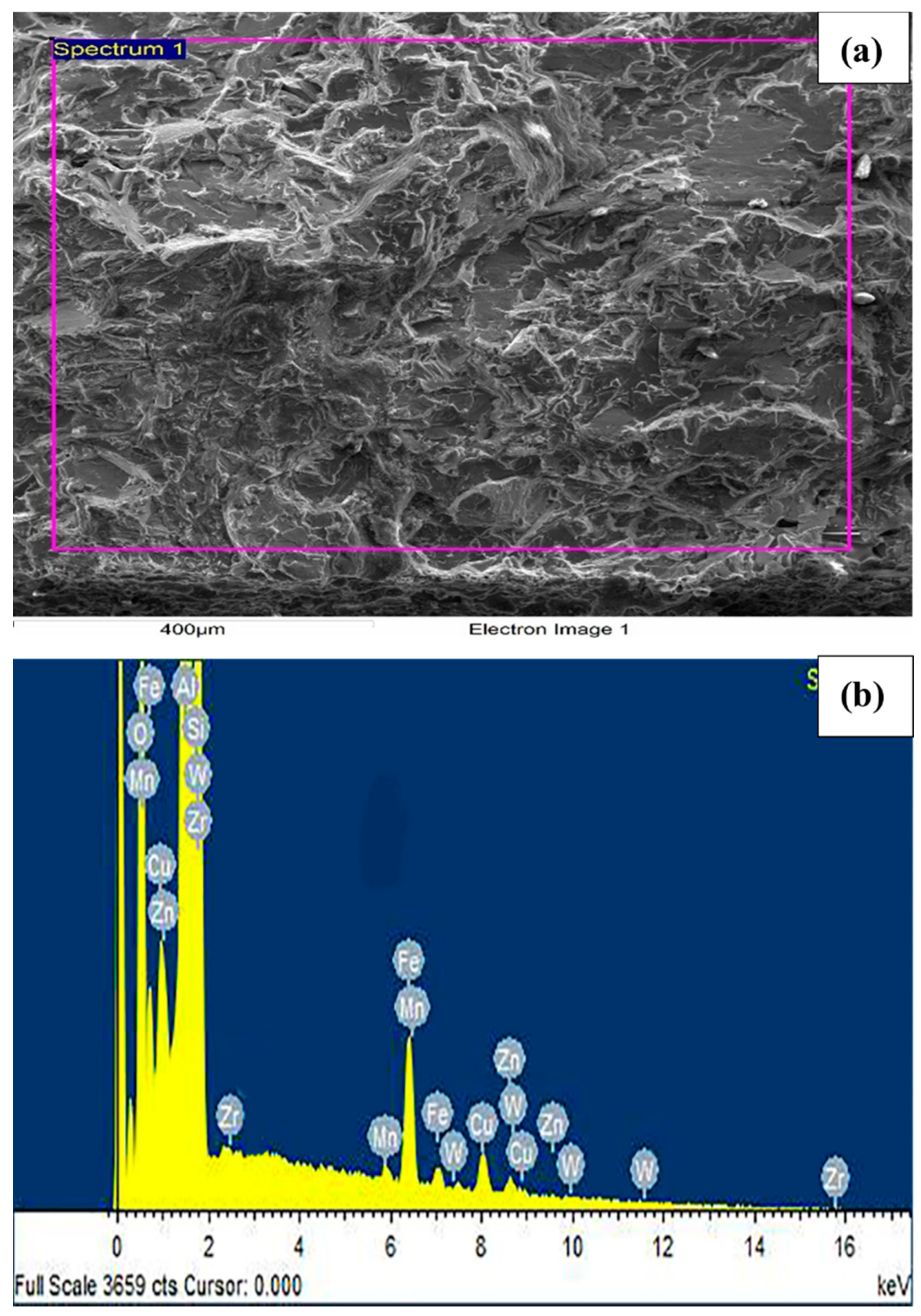
EDS spectra shows in the (Figure 7a,b) revealed the presence of bright phases of Zirconium (Zr). Tungsten (W) and oxygen (O) were also found in the selected spectrum region which prove the presence of ZrW2O8 (zirconium tungstate) particles in the Al composite. Al-Si-Cu alloy offer good casting characteristics, improved machineability with reduced ductility, higher strength and hardness [28]. During the initial alloy solidification cycle, micro-sized structures combine and develop primary phases. Other than this Si eutectic particles forms structures, i.e., Si-Cu, Si-Mg-Cu, and Si-Mg-Fe.

3.3. Hardness Effect

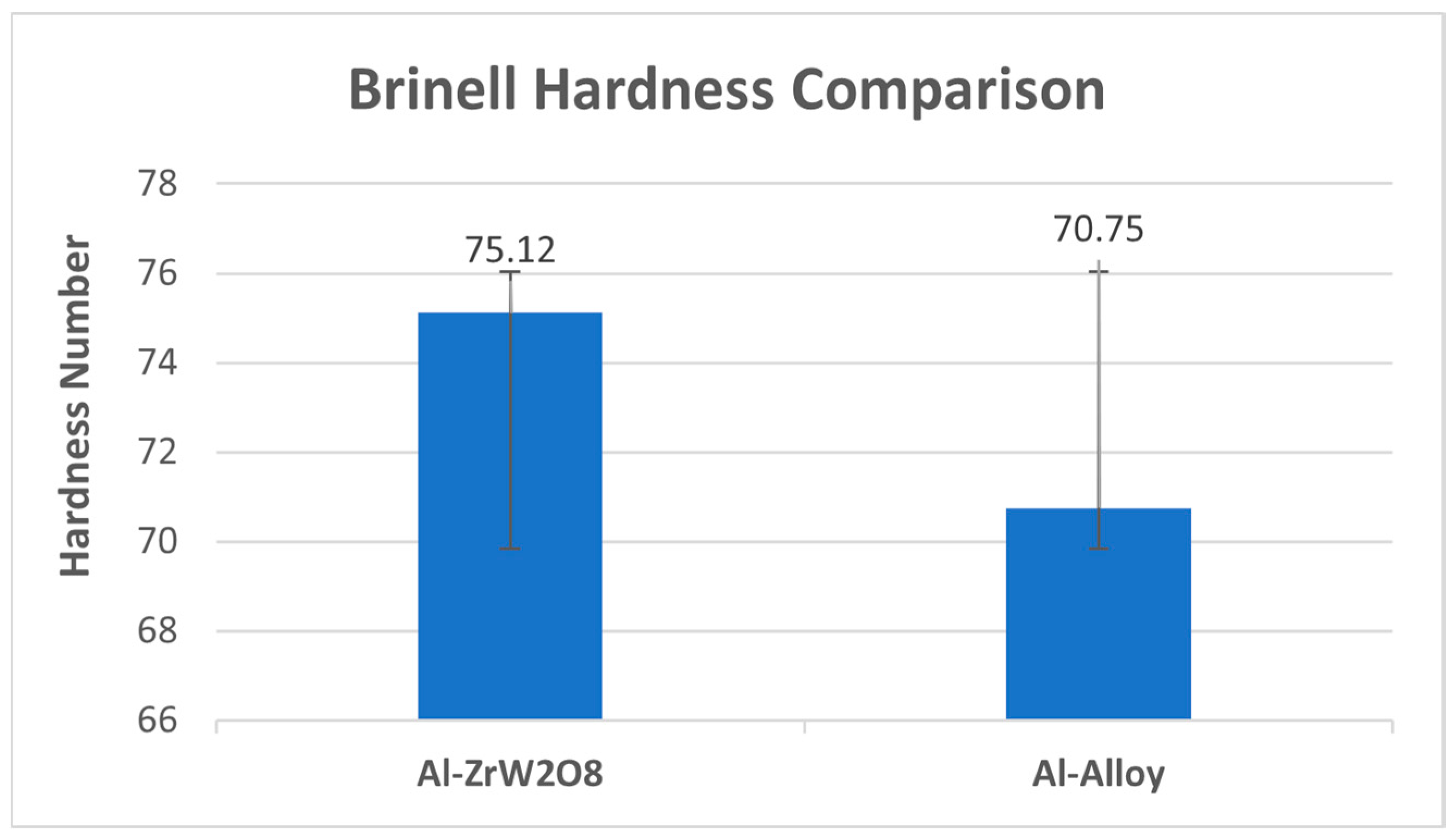
Hardness of all the 4 samples of each reinforced and unreinforced alloy was observed by Brinell hardness test and shown in Figure 8. The average hardness value of ZrW2O8 reinforced alloy samples increased 7% as compared to the average hardness value of base aluminum alloy. The improvement in the hardness value of composite as compared to the base alloy is due to the addition of ceramic powders which act as hindrance to the motion of dislocations [36,37]. Inclusion of ZrW2O8 particles hindered the plastic formation that increased the hardness of the composite [21]. The enhancement of Brinell Hardness values in ZrW2O8 reinforced A356 composite is in good agreement with microstructural analysis, where the base alloy contains more amount of porosity as compared to ZrW2O8 reinforced A356 composite. The Brinell hardness value increases with increasing the ceramic inclusions [38].
The ceramic inclusion also has a role in the hardness of the material. The hardness of ceramic reinforced alloy is higher that of the base alloy due to the strengthening of the alloy caused by the particles. These particles help to resist in the dislocation of motion. The enhancement in hardness is also due to the refining in the grain size and eutectic structure of the alloy which can be easily observed by microscopic images. Increasing the hardness with the incorporation of zirconium tungstate can be linked to the presence of hard particles in the soft matrix which act as barrier to the movement of the dislocation [5].

3.4. Tensile Properties

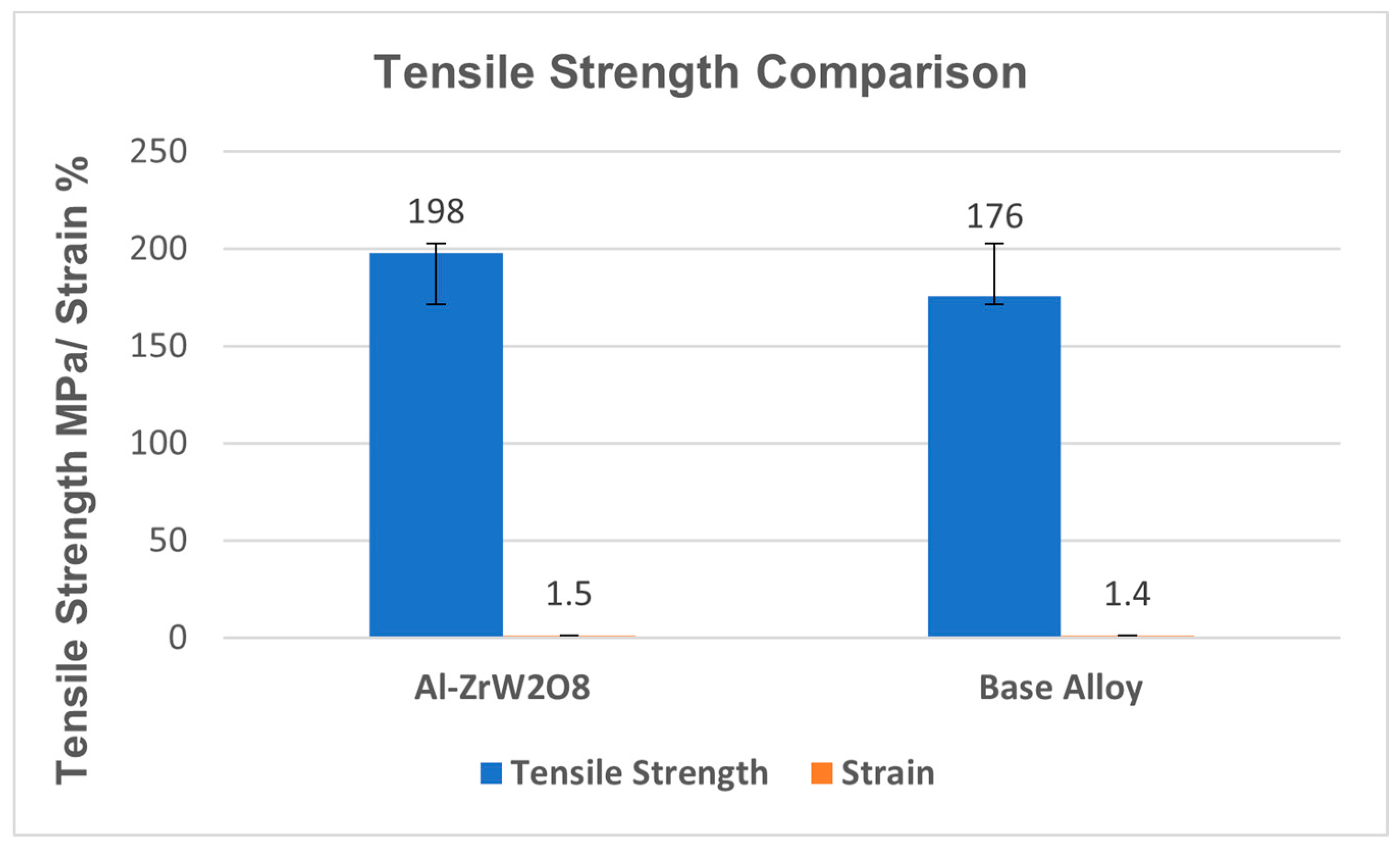
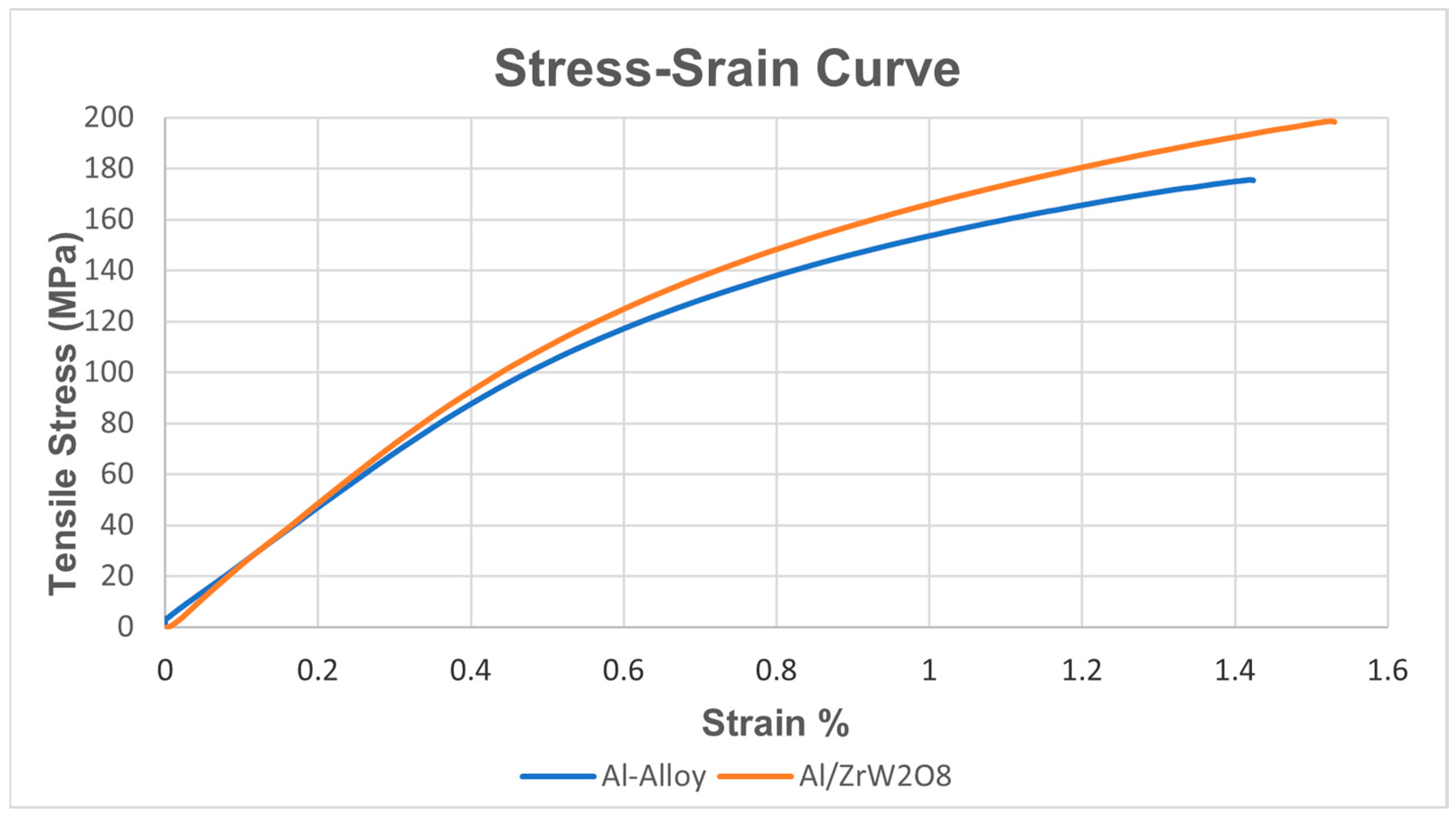
Mechanical properties of Al-ZrW2O8 composite and base Aluminum alloy is shown on the Table 3. Results showed an increase in the tensile, yield and hardness values of the composite as compared to the base aluminum alloy [19,20]. The composite shows 13% increase in the tensile strength as compared the base aluminum alloy. The increase in percentage elongation from 1.5% to 1.4% also takes place with reduction in the cross-sectional area. The increase in these values are due to the composite formation, reinforcement and good interface (see Figure 9) [39]. Other reason is that the voids and porosity contents are more in casted aluminum alloy as compared to the composite, that is in good agreement to microstructural study [24]. Composite like role of Cu- and Fe-containing silicon particles also played a great role for the tensile strengthening of the samples (Figure 3b). Low degree of porosity level in composite also helps it to easily transfer the applied stress and enhance its tensile stress [12]. Addition of ZrW2O8 ceramic plays a positive role in the enhancement of the tensile strength and elongation of the modified alloy as compared to the unmodified [37]. The presence of these micro-sized particles hinders the dislocation during the tensile deformation; thus, it causes to increase the strength of casted composite.
It can be seen from the Figure 10 that the tensile strength of ceramic added alloy is higher than the base alloy. It is suggested that particle strengthening, and grain refinement may enhance the tensile strength of the ceramic reinforced alloy. The major enhancement may be due to the grain refinement as the particle’s inclusion act as hindrance to dislocation and restrict them against the applied strength [29]. The strength of material can also be evaluated by its porosity level. It can be observed from the microstructural images that the composite samples have less porosity contents as compared to the base alloy. The presence of pores results in the decrease of the tensile strength and mechanical properties [38].

3.5. Fatigue Performance

Fatigue tests results are shown below in Figure 11. The number of cycles to fracture was drawn against the alternating stress amplitude. In general, the fatigue life of a sample decreases with increasing the stress amplitude. At lower stress, the fatigue life increases and at higher stress, the fatigue life decreases [11]. As the load increases from 30% to 35%, the value decreases from 40,911 to 12,817 for the base aluminum alloy and from 67,201 to 23,981 for the composite alloy [40]. It is also evident that aluminum and its most of the alloys do not show a continuous fatigue limit, but its fatigue strength decreases continuously with increase in the number of cycles [15].
Figure 10 shows the result of fatigue life of casted base aluminum alloy and composite, tested at stress ratio, R (σ maxmin) = 0.1 and four different level of stress levels: 25, 30, 35, and 40 MPa. From microstructural analysis, it was observed that the most of the cracks nucleated from porosity and oxide films. Mostly fatigue crack initiated from single site. But, large amount of porosity may result in multidirectional fatigue crack. River-like ridges and striations were observed in the fatigue region, which indicate that the samples were ductile in nature. In the overload region, dimples and cracked particles of eutectic silicon were observed. Tear ridges and dimples are the sign of ductile nature of the crack [41,42]. These were the result of tensile rupture. From Figure 11, it was observed that fatigue life of composite is higher than the base aluminum alloy due to the inclusion of ceramic particles in the aluminum melt. It is also observed that addition of 4% ceramic particles increases the fatigue life more than the 50% of the base aluminum alloy [14]. In the composite sample, the pores and defects are less in number as compared to the base aluminum alloy (Figure 4a). Therefore, in defect-free samples, cracks mostly initiate from slip bands and eutectic particles, which increase the fatigue life of the samples.
Porosity and defects have an important role on the crack initiation and propagation. Larger the porosity, larger will be the crack initiation and more rapidly it propagates. So, the fatigue life of material is directly proportional to its defects, the larger the defect size the lower will be fatigue life. The figure shows that the samples having ceramic inclusions have greater fatigue strength than the base aluminum alloy [43] that is well supported by microstructural analysis.

4. Conclusions

  • In this study, the effect of a 4% zirconium tungstate-reinforced A356 alloy on the microstructure, fatigue, and mechanical properties were investigated. The ceramic inclusion had shown noticeable improvements in fatigue behavior, and mechanical properties (i.e., hardness and tensile strength).
  • The existence of ZrW2O8 particles refined the microstructure of the aluminum matrix.
  • The hardness value of composite increases by 7% compared to the casted aluminum.
  • Tensile strength of the composite increases up to 13% compared to the base alloy.
  • The addition of ZrW2O8 causes improvement in the fatigue life of the aluminum alloy; the addition of 4% ceramic powder increased the fatigue life more than 50% of the base alloy. Fatigue life would be further increased if defects were minimized during casting and if aging of the sample was done.

Author Contributions

Conceptualization, M.R. and A.H.; methodology, M.R. and M.I.; software, M.R. and M.I.; formal analysis, M.R. and A.H.; investigation, M.R., A.H., H.A. and R.A.M.; writing—original draft preparation, M.R., H.A. and R.A.M.; writing—review and editing, M.R., H.A., M.A., M.S. and R.A.M.; supervision, H.A.; project administration, H.A.; funding acquisition, H.A. All authors have read and agreed to the published version of the manuscript.

Funding

This project was supported the Deanship of Scientific Research at Prince Sattam bin Abdul aziz University, under the research project no. 2020/01/17063.

Conflicts of Interest

The authors declare no conflict of interest.

References

  1. Harlow, D.G.; Nardiello, J.; Payne, J. The effect of constituent particles in aluminum alloys on fatigue damage evolution: Statistical observations. Int. J. Fatigue 2010, 32, 505–511. [Google Scholar] [CrossRef]
  2. Tajiri, A.; Nozaki, T.; Uematsu, Y.; Kakiuchi, T.; Nakajima, M.; Nakamura, Y.; Tanaka, H. Fatigue Limit Prediction of Large Scale Cast Aluminum Alloy A356. Procedia Mater. Sci. 2014, 3, 924–929. [Google Scholar] [CrossRef] [Green Version]
  3. Chandra, B.; Kumar, J.; Singh, H. Fabrication and characterisation of Al2O3/aluminium alloy 6061 composites fabricated by Stir casting. Mater. Today Proc. 2017, 4, 2783–2792. [Google Scholar]
  4. Hashim, J.; Looney, L.; Hashmi, M.S.J. Metal matrix composites: Production by the stir casting method. J. Mater. Process. Technol. 1999, 92–93, 1–7. [Google Scholar] [CrossRef]
  5. Thomas, A.T.; Parameshwaran, R.; Muthukrishnan, A.; Kumaran, M.A. Development of Feeding & Stirring Mechanisms for Stir Casting of Aluminium Matrix Composites. Procedia Mater. Sci. 2014, 5, 1182–1191. [Google Scholar] [CrossRef]
  6. Prabu, S.B.; Karunamoorthy, L.; Kathiresan, S.; Mohan, B. Influence of stirring speed and stirring time on distribution of particles in cast metal matrix composite. J. Mater. Process. Technol. 2006, 171, 268–273. [Google Scholar] [CrossRef]
  7. Chen, L.; Qi, Y.; Fei, Y.; Du, Z. Enhanced Mechanical Properties and Thermal Conductivity for GNPs/Al2024 Composites with In Situ SiC Nanorods. Met. Mater. Int. 2020, 26, 1–8. [Google Scholar] [CrossRef]
  8. Yang, Y.; Lan, J.; Li, X. Study on bulk aluminum matrix nano-composite fabricated by ultrasonic dispersion of nano-sized SiC particles in molten aluminum alloy. Mater. Sci. Eng. A 2004, 380, 378–383. [Google Scholar] [CrossRef]
  9. Hashim, J.; Looney, L.; Hashmi, M.S.J. Particle distribution in cast metal matrix composites—Part I. J. Mater. Process. Technol. 2002, 123, 251–257. [Google Scholar] [CrossRef]
  10. Srinivasan, R.; Ashraf Imam, M.; Srivatsan, T.S. Fatigue of Materials III—Advances and Emergences in Understanding; Springer: Cham, Switzerland, 2016; pp. 3–30. [Google Scholar]
  11. Elhadari, H.A.; Patel, H.A.; Chen, D.L.; Kasprzak, W. Tensile and fatigue properties of a cast aluminum alloy with Ti, Zr and V additions. Mater. Sci. Eng. A 2011, 528, 8128–8138. [Google Scholar] [CrossRef]
  12. Mazahery, A.; Shabani, M.O. Characterization of cast A356 alloy reinforced with nano SiC composites. Trans. Nonferrous Met. Soc. China 2012, 22, 275–280. [Google Scholar] [CrossRef]
  13. Srivatsan, T.S.; Al-Hajri, M. The fatigue and final fracture behavior of SiC particle reinforced 7034 aluminum matrix composites. Compos. Part B Eng. 2002, 33, 391–404. [Google Scholar] [CrossRef]
  14. Winter, L.; Hockauf, K.; Lampke, T. Temperature and Particle Size Influence on the High Cycle Fatigue Behavior of the SiC Reinforced 2124 Aluminum Alloy. Metals 2018, 8, 43. [Google Scholar] [CrossRef] [Green Version]
  15. Bekheet, N.E.; Gadelrab, R.M.; Salah, M.F.; El-azim, A.N.A. The effects of aging on the hardness and fatigue behavior of 2024 Al alloy /SiC composites. Mater. Des. 2002, 23, 153–159. [Google Scholar] [CrossRef]
  16. Afkham, Y.; Khosroshahi, R.A.; Rahimpour, S.; Aavani, C.; Brabazon, D.; Mousavian, R.T. Enhanced mechanical properties of in situ aluminium matrix composites reinforced by alumina nanoparticles. Arch. Civ. Mech. Eng. 2018, 18, 215–226. [Google Scholar] [CrossRef] [Green Version]
  17. Sajjadi, S.A.; Ezatpour, H.R.; Parizi, M.T. Comparison of microstructure and mechanical properties of A356 aluminum alloy/Al2O3 composites fabricated by stir and compo-casting processes. Mater. Des. 2012, 34, 106–111. [Google Scholar] [CrossRef]
  18. Zhu, S.J.; Iizuka, T. Fatigue behavior of Al18B4O33 whisker-framework reinforced Al matrix composites at high temperatures. Compos. Sci. Technol. 2003, 63, 265–271. [Google Scholar] [CrossRef]
  19. Jeykrishnan, J.; Nathan, S.J.; Karthik, M.R. Fabrication and Characterization of Aluminum Titanium Di-Boride Metal Matrix Composites using Stir Casting Technique. Int. J. Mech. Eng. Technol. 2017, 8, 13–18. [Google Scholar]
  20. Fu, H.; Liang, Y. Study of the Surface Integrity and High Cycle Fatigue Performance of AISI 4340 Steel after Composite Surface Modification. Metals 2019, 9, 856. [Google Scholar] [CrossRef] [Green Version]
  21. Kumar, K.R.; Pridhar, T.; Balaji, V.S.S. Mechanical properties and characterization of zirconium oxide (ZrO2) and coconut shell ash (CSA) reinforced aluminium (Al 6082) matrix hybrid composite. J. Alloys Compd. 2018, 765, 171–179. [Google Scholar] [CrossRef]
  22. Mummoorthi, D.; Rajkumar, M.; Kumar, S.G. Advancement and characterization of Al-Mg-Si alloy using reinforcing materials of Fe2O3 and B4C composite produced by stir casting method. J. Mech. Sci. Technol. 2019, 33, 3213–3222. [Google Scholar] [CrossRef]
  23. Pandiyarajan, R.; Maran, P.; Marimuthu, S.; Ganesh, K.C. Mechanical and tribological behavior of the metal matrix composite AA6061/ZrO2/C. J. Mech. Sci. Technol. 2017, 31, 4711–4717. [Google Scholar] [CrossRef]
  24. Madhusudan, S.; Sarcar, M.M.M.; Rao, N.B.R.M. Mechanical properties of Aluminum-Copper(p) composite metallic materials. J. Appl. Res. Technol. 2016, 14, 293–299. [Google Scholar] [CrossRef] [Green Version]
  25. Grima, J.N.; Zammit, V.; Gatt, R. Negative thermal expansion. J. Phys. Condens. Matter 2005, 17, 16–29. [Google Scholar]
  26. Takenaka, K. Negative thermal expansion materials: Technological key for control of thermal expansion. Sci. Technol. Adv. Mater. 2012, 13, 013001. [Google Scholar] [CrossRef]
  27. Mondolfo, L.F. Aluminum Alloys: Structure and Properties, 1st ed.; Butterworths-Heinemann: Oxford, UK, 1976; pp. 86–87. [Google Scholar]
  28. Kaufman, J.G.; Rooy, E.L. Aluminum Casting Alloys: Properties, Processes, and Applications, 1st ed.; ASM International: Cleveland, OH, USA, 2004; pp. 13–33. [Google Scholar]
  29. González, R.; Martínez, D.I.; González, J.A.; Talamantes, J.; Valtierra, S.; Colás, R. Experimental investigation for fatigue strength of a cast aluminum alloy. Int. J. Fatigue 2011, 33, 273–278. [Google Scholar] [CrossRef]
  30. Standards For Aluminum Sand and Permanent Mold Castings; Engineering Series(E); 2005; pp. 1–3. Available online: https://www.aluminum.org/sites/default/files/Sand%20and%20Permanent%20Mold%20Casting%20Errata%20watermark.pdf (accessed on 4 November 2020).
  31. Standard Test Method for Plane-Strain Fracture Toughness of Metallic Materials 1; ASTM International: West Conshohocken, PA, USA, 1997; pp. 1–31.
  32. Graff, W.R.; Sargent, D.C. A new grain-boundary etchant for aluminum alloys. Metallography 1981, 14, 69–72. [Google Scholar] [CrossRef]
  33. Kim, K.S.; Sung, S.-Y.; Han, B.-S.; Jung, C.-Y.; Lee, K.-A. High temperature high cycle fatigue behavior of new aluminum alloy strengthened by (Co, Ni)3Al4 particles. Met. Mater. Int. 2014, 20, 243–248. [Google Scholar] [CrossRef]
  34. Wang, Q.G. Microstructural Effects on the Tensile and Fracture Behavior of Aluminum Casting Alloys A356/357. Metall. Mater. Trans. A 2003, 34, 2887–2899. [Google Scholar] [CrossRef]
  35. Srivatsan, T.S.; Anand, S.; Sriram, S.; Vasudevan, V.K. The high-cycle fatigue and fracture behavior of aluminum alloy 7055. Mater. Sci. Eng. A 2000, 281, 292–304. [Google Scholar] [CrossRef]
  36. Gholipour, V.; Shamanian, M.; Ashrafi, A.; Maleki, A. Development of Aluminium-Nanoclay Composite by Using Powder Metallurgy and Hot Extrusion Process. Met. Mater. Int. 2020, 1–14. [Google Scholar] [CrossRef]
  37. Qian, H.; Zhu, D.; Hu, C.; Jiang, X. Effects of Zr Additive on Microstructure, Mechanical Properties, and Fractography of Al-Si Alloy. Metals 2018, 8, 124. [Google Scholar] [CrossRef] [Green Version]
  38. Zhukov, I.A.; Kozulin, A.A.; Khrustalyov, A.P.; Kahidze, N.I.; Khmeleva, M.G.; Moskvichev, E.N.; Lychagin, D.V.; Vorozhtsov, A.B. Pure Aluminum Structure and Mechanical Properties Modified by Al 2O3 Nanoparticles and Ultrasonic Treatment. Metals 2019, 9, 1199. [Google Scholar] [CrossRef] [Green Version]
  39. Almotairy, S.M.; Boostani, A.F.; Hassani, M.; Wei, D.; Jiang, Z.Y. Mechanical Properties of Aluminium Metal Matrix Nanocomposites Manufactured by Assisted-Flake Powder Thixoforming Process. Met. Mater. Int. 2019. [Google Scholar] [CrossRef]
  40. Yan, C.; Wang, J.; Song, X. Fatigue behavior and damage mechanism of aluminum foam sandwich with carbon-fiber face-sheets. J. Mech. Sci. Technol. 2020, 34, 1119–1127. [Google Scholar] [CrossRef]
  41. Yang, Y.; Jiang, R.; Li, X.; Zhang, Y.; Li, R. Effect of Nanoparticle Content on the Microstructural and Mechanical Properties of Forged and Heat-Treated TiC/2219 Nanocomposites. Metals 2019, 9, 982. [Google Scholar] [CrossRef] [Green Version]
  42. Wang, Q.; Apelian, D.; Lados, D.A. Fatigue behavior of A356-T6 aluminum cast alloys. Part I. Effect of casting defects. J. Light Met. 2001, 1, 73–84. [Google Scholar] [CrossRef]
  43. Srivatsan, T.S. The low-cycle fatigue behaviour of composite. Int. J. Fatigue 1992, 3, 173–182. [Google Scholar] [CrossRef]
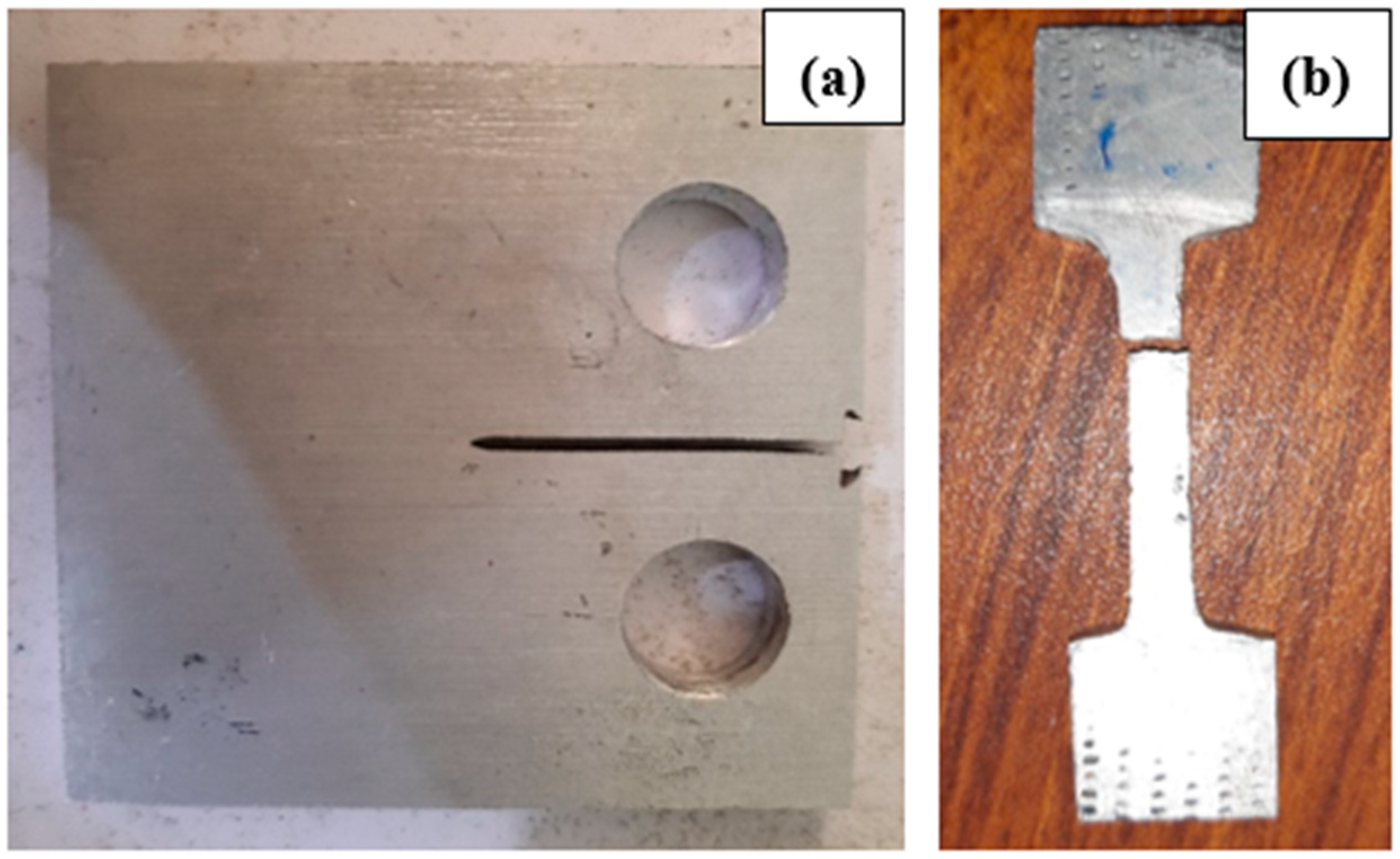
Figure 1. (a) Sample after cutting, machining, drilling, and notch making. (b) Fracture sample after tensile test.
Metals 10 01492 g001
Figure 2. (a) Fatigue testing of C(T) sample (b) Break sample after fatigue test.
Metals 10 01492 g002
Figure 3. SEM images of fracture surface of base aluminum alloy: (a) overall image of the notch area of the specimen from where crack started, (b) fracture surface showing the pores dimension, (c) striations/river ridges depicting the crack propagation, and (d) slip bands on the fracture surface of the specimen.
Metals 10 01492 g003
Figure 4. SEM images of fracture surface of composite: (a) overall image of the notch area of the specimen from where crack started, (b) crack initiation site of the composite from where the crack originated, (c) plane surfaces showing the slip bands and curved pattern depicts the river ridges of the crack pattern, and (d) dimples and voids shows that the crack was rupture in nature.
Metals 10 01492 g004
Figure 5. Optical micrographs of base Al-alloy and ceramic-reinforced composite: (a) low magnification of base alloy displaying the distribution of porosity, (b) high magnification of base alloy showing the microstructure of eutectic silicon particles and aluminum dendrites, (c) low magnification of composite showing the eutectic structure, and (d) high magnification of composite showing the distribution of ZrW2O8 into aluminum alloy.
Metals 10 01492 g005
Figure 6. SEM images and EDS spectra show the chemical composition of base aluminum alloy (a). Spectra on the SEM image of the base alloy (b) with phases of iron, magnesium, zinc, silicon, and copper.
Metals 10 01492 g006
Figure 7. SEM images and EDS spectra show the chemical composition of composite (a). Selected spectrum on SEM image of composite (b) phases of silicon, manganese, zirconium, tungsten, and other components of A356.
Metals 10 01492 g007
Figure 8. Brinell Hardness value of base aluminum alloy and Al/ZrW2O8 with standard deviation.
Metals 10 01492 g008
Figure 9. Effect of ceramic on the tensile strength of the base alloy and composite with standard deviation.
Metals 10 01492 g009
Figure 10. Effect of ceramic on tensile strength of base aluminum alloy and composite.
Metals 10 01492 g010
Figure 11. Stress amplitude and fatigue life comparison of base aluminum alloy and Al/ZrW2O8.
Metals 10 01492 g011
Table 1. Chemical composition of aluminum alloy A356.
Si %Cu%Mg%Mn%Ni%Zn%Fe%Ti%Al%
7.50.250.200.350.20.350.80.25Bal.
Table 2. Chemical composition and properties of ZrW2O8.
ZrW2O8Impurities (%Max)DensityParticle SizeAppearance
(%Min)Fe2O3SiO2MoTiO2g/cm3(D50, μm)Powder
99.60.0010.00710.0020.00625.071.86Light Yellowish
Table 3. Mechanical properties of the A356 and A356/ ZrW2O8.
MaterialsBrinell HardnessYield Strength (MPa)Tensile Strength (MPa)Young’s Modulus (GPa)Elongation (%)
A35670.75154.52175.6021.71.5
A356-ZrW2O875.12174.65198.4723.82
Publisher’s Note: MDPI stays neutral with regard to jurisdictional claims in published maps and institutional affiliations.