Article

Effect of Laser Heat-Treatment and Laser Nitriding on the Microstructural Evolutions and Wear Behaviors of AISI P21 Mold Steel

1
Department of Materials Science and Engineering, Inha University, Incheon 22212, Korea
2
Laser and Electron Beam Application Department, Korea Institute of Machinery and Materials, Daejeon 34103, Korea
3
Department of Materials Science and Engineering, Hanbat National University, Daejeon 22212, Korea
4
Department of Nano Materials Science and Engineering, Kyungnam University, Changwon 51767, Korea
*
Authors to whom correspondence should be addressed.
Won-Sang Shin and Hyun Jong Yoo contributed equally to this work.
Metals 2020, 10(11), 1487; https://doi.org/10.3390/met10111487
Submission received: 30 September 2020 / Revised: 19 October 2020 / Accepted: 3 November 2020 / Published: 7 November 2020
(This article belongs to the Special Issue Application of Correlative Microscopy in Metallurgical Research)

Abstract

:
Laser heat-treatment and laser nitriding were conducted on an AISI P21 mold steel using a high-power diode laser with laser energy densities of 90 and 1125 J/mm2, respectively. No change in surface hardness was observed after laser heat-treatment. In contrast, a relatively larger surface hardness was measured after laser nitriding (i.e., 536 HV) compared with that of the base metal (i.e., 409 HV). The TEM and electron energy loss spectroscopy (EELS) analyses revealed that laser nitriding induced to develop AlN precipitates up to a depth of 15 μm from the surface, resulting in surface hardening. The laser-nitrided P21 exhibited a superior wear resistance compared with that of the base metal and laser heat-treated P21 in the pin-on-disk tribotests. After 100 m of a sliding distance of the pin-on-disk test, the total wear loss of the base metal was measured to be 0.74 mm3, and it decreased to 0.60 mm3 for the laser-nitrided P21. The base metal and laser heat-treated P21 showed similar wear behaviors. The larger wear resistance of the laser-nitrided P21 was attributed to the AlN precipitate-induced surface hardening.

1. Introduction

AISI P21 steel is used for plastic injection molds due to its good mechanical properties with excellent machinability [1]. Plastic injection molds are expected to be used for several million shots for the mass production of plastic products. However, the molds can be damaged by wear, corrosion, and fatigue during plastic injection molding. The damaged molds should be replaced to maintain a satisfactory quality of plastic products, thus increasing the production cost. Appropriate surface treatments can prevent damages to the mold, resulting in an extended mold lifespan. Several studies have investigated the application of surface treatments to mold steels and tool steels in the form of surface heat-treatment [2,3,4,5], nitriding [3,6,7,8], surface coating and alloying [9,10,11,12], and peening [5,13,14]. Lee et al. [2] investigated the laser melting-induced microstructural evolution and surface hardening of SM45C mold steel. Telasang et al. [4] reported that laser surface hardening/melting improved the wear and corrosion resistances of AISI H13 tool steel. However, only a few studies have reported the influence of surface treatments on the microstructure, mechanical properties, and functional properties of AISI P21 mold steel. Our previous studies [3,7] investigated the influence of laser heat-treatment and laser nitriding on the microstructure and microhardness of P21 steel. These studies revealed that the laser heat-treatment did not induce surface hardening, and the laser nitriding parameters affected the microhardness and nitriding thickness. Wen [8] reported an increase in wear and corrosion resistances after the plasma nitriding of P21 steel.
Nitriding is a heat-treatment process that uses the diffusion of nitrogen into the subsurface of metals to attain surface hardening [15]. A conventional plasma nitriding process has been widely applied in manufacturing gears, die-casting tools, camshafts, crankshafts, molds, etc., to improve wear, corrosion, and fatigue resistances [8,16,17,18,19]. The concept of laser nitriding was first suggested by Katayama et al. [20] in 1983 to achieve a higher speed process than plasma nitriding. Various studies have been conducted to investigate the influences of laser nitriding on the microstructure, mechanical properties, and functional properties of materials [21,22,23]. A pulsed CO2 laser was employed for laser nitriding to induce the formation of martensite and nitride in tool steels and stainless steel, resulting in an increase in surface hardness and wear and corrosion resistances. An application of a continuous-wave CO2 laser with N2 gas on SAE 52,100 steel led to the formation of a thin nitride layer [24]. An enhancement in wear resistance was observed due to the formation of a hard nitride layer. Binczycka et al. [25] and Illgner et al. [26] used an excimer laser to obtain laser-nitrided stainless steel and iron, respectively. They revealed that nitrogen content and laser parameters (i.e., laser energy density and the number of pulses) strongly affect the formation of nitrides. Copola et al. [27] conducted the laser nitriding of low carbon steel using an neodymium-doped yttrium aluminum garnet (Nd:YAG) laser and an excimer laser and achieved an increased in corrosion resistance. Ingelgem et al. [28] achieved surface hardening and improved corrosion resistance of martensitic stainless steel using a diode laser. However, limited studies have investigated the laser nitriding process for mold steels, with a lack of discussion on the microstructural evolution after laser nitriding [7].
Laser-based surface treatments are widely used for the surface modification of metals due to their high precision, high speed, and selectivity. In this study, laser heat-treatment and laser nitriding were applied to AISI P21 mold steel using a high-power diode laser to obtain a high-durability plastic injection mold. The laser treatment-induced microstructural evolutions were characterized by TEM and EELS analyses. Moreover, the microhardness was compared by using measurements from before and after the laser treatments. Additionally, a pin-on-disk tribotest was performed for the base metal, laser heat-treated P21, and laser-nitrided P21 to investigate the correlation between the laser treatments and wear behaviors.

2. Materials and Methods

2.1. Materials and Experimental Set-Up for Laser Heat-Treatment and Laser Nitriding
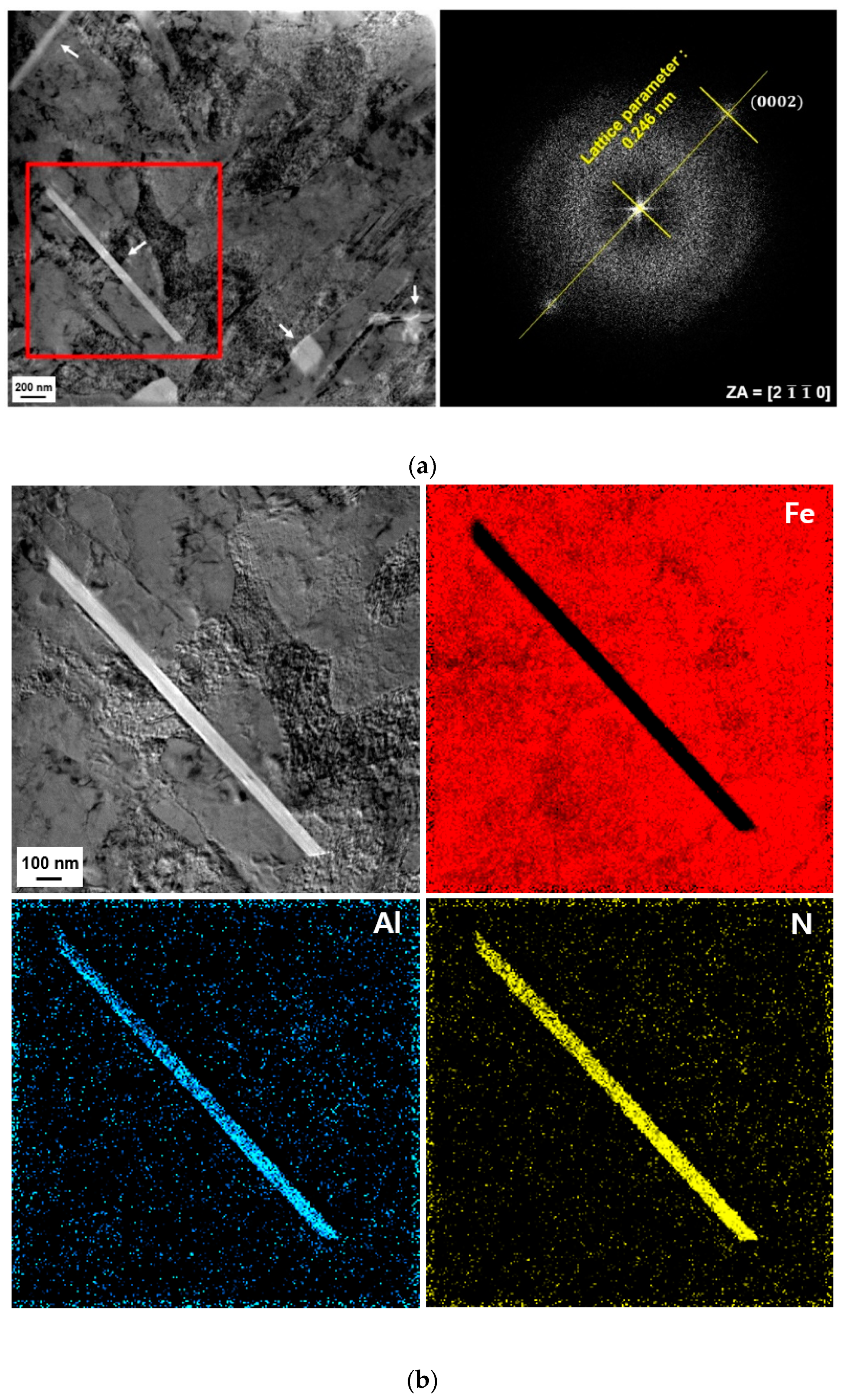
A commercial AISI P21 steel (NAK80, Daido Steel Co., Ltd.) with dimensions of 100 (W) × 150 (D) × 15 (H) mm3 was used for this study [1]. The chemical composition of P21 steel is listed in Table 1. Figure 1a,b shows the experimental set-up for the laser heat-treatment (LH) and laser nitriding (LN) processes, respectively. A continuous-wave mode of a 4 kW diode laser (TeraBlade, TeraDiode Inc., Wilmington, MA, USA) with a wavelength of 970 nm was employed for both LH and LN. The laser beam had a flat-top energy distribution with dimensions of 6 (W) × 4 (D) mm2. The laser head was mounted on a six-axis multi-joint robot for the laser beam scanning. The laser head was tilted 5° to a normal direction to the specimen to inhibit the laser system damage from the laser beam reflection. For the LH samples, the laser beam scan speed and laser energy density were set to 5.0 mm/s and 90 J/mm2, respectively, corresponding to a specimen surface temperature of 1200 °C. A two-color pyrometer (LASCON, Dr. Mergenthaler GmbH & Co. KG, Neu-Ulm, Germany) was coaxially fixed on the laser head and measured the surface temperature of the specimen. The pyrometer was synchronized with the diode laser to maintain the specimen surface temperature at 1200 °C by controlling the laser power in real-time. A vacuum chamber with dimensions of 200 (W) × 200 (D) × 200 (H) mm3 was employed to conduct the laser nitriding process under an N2 atmosphere (Figure 1b). The vacuum chamber was evacuated down to 3.0 × 10⁻² torr, followed by filling pure nitrogen gas (purity: 99.99%) up to 7.0 × 10² torr. The N2 atmosphere was maintained during the LN process. The laser beam was applied to the P21 specimens through a transparent glass window of the gas chamber. The laser beam scan speed and laser energy density were set to 0.4 mm/s and 1125 J/mm2, respectively. The surface temperature of the specimen could not be measured due to the usage of the vacuum chamber and the limitation of the pyrometer. The laser energy density was calculated using Equation (1).
Laser energy density (J/mm2) = laser power (W)/(beam depth (mm) × scan speed (mm/s))

2.2. Microstructure

An X-ray diffraction (XRD; SmartLab, Rigaku) analysis of base metal (BM), LH P21, and LN P21 was conducted with Cu-Kα radiation (λ = 1.541 Å) at a tube voltage of 45 kV and a current of 200 mA. The microstructures of BM, LH P21, and LN P21 were examined via optical microscopy (OM; ECLIPS MA 200, Nikon, Tokyo, Japan), scanning electron microscopy (SEM; SNE-4500M, SEC, Suwon, Korea), and transmission electron microscopy (TEM). Two different TEM analyses were conducted using the thin film technique (JEM-2200FS, JEOL, Tokyo, Japan) and the replica technique (JEM-2010, JEOL, Tokyo, Japan). For the thin-film technique, the TEM samples were prepared using a lift-out technique by the focused ion beam (FIB; Helios NanoLab DualBeam 650, FEI, Hillsboro, OR, USA) method. For the LH P21, the chemical composition was confirmed via energy-dispersive X-ray spectroscopy (EDS, X-Max 65T, Oxford, Abingdon, UK) during TEM analysis. For the LN P21, the elemental distribution mapping was conducted for Fe, Al, and N using an energy-filtered transmission electron microscope (EFTEM). Each element signal was extracted from the high spatial resolution EELS peaks (i.e., Fe-L3 edge (708 eV), Al-L2 and -L3 edges (73 eV), and N-K edge (401 eV)).

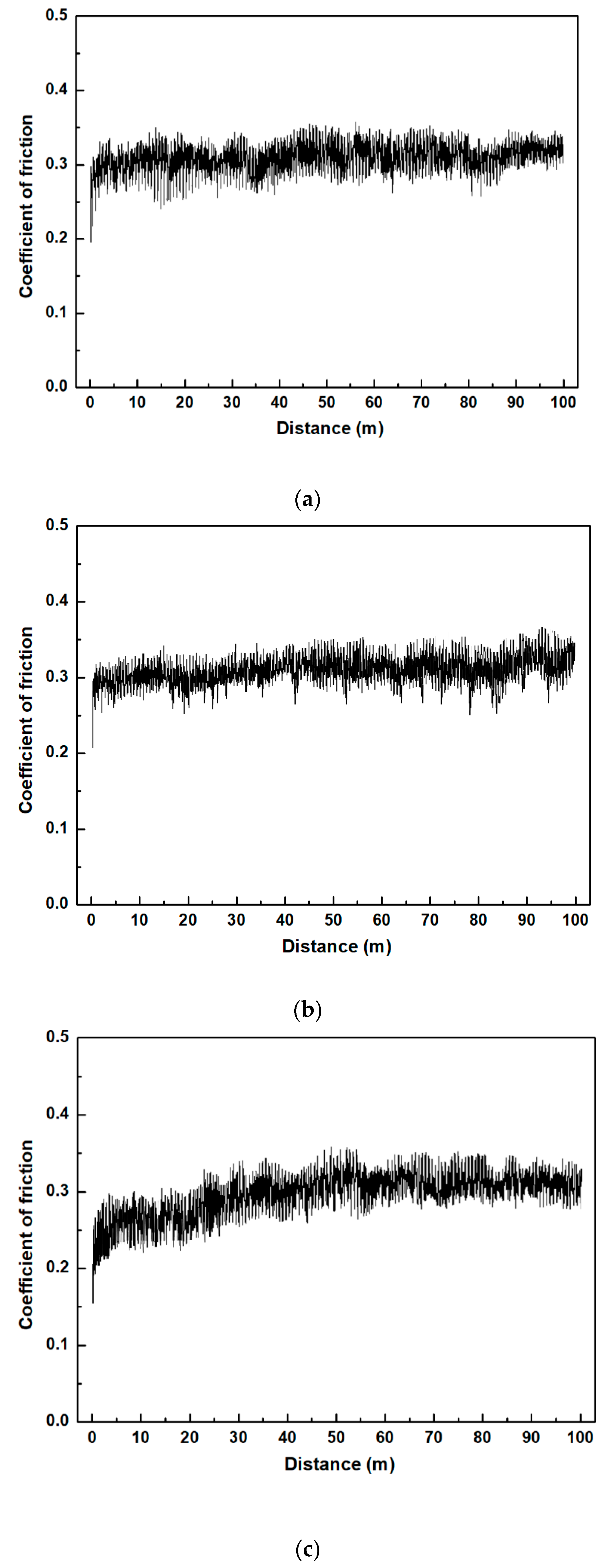
2.3. Microhardness and Tribological Test

The microhardness was measured using a Vickers hardness tester (MMT-X7, Matsuzawa, Akita, Japan) with a load of 0.01 kgf and a holding time of 10 s. The microhardness was measured three times, and the obtained values were averaged.
Dry sliding wear tests were performed by a pin-on-disk tribometer (CETR UMT-2, Bruker, Billerica, MA, USA) with a sliding speed of 27.8 mm/s and a normal load of 30 N. The total sliding distance was 100 m, and the worn thickness was measured at sliding distance intervals of 25 m. The dimensions of the cube P21 specimens were 3 (W) mm × 3 (D) mm × 3 (H) mm for the pin-on-disk test. A gray cast-iron disk with a diameter of 142 mm, a thickness of 6 mm, and a surface hardness of 245 HV was used as the counter material (Figure 2). Before the tribotests, all the specimens were polished with SiC papers, and the average surface roughness (Ra) was approximately 0.8 μm. After the tribotest, the average of surface roughness and surface morphology at the worn surface were analyzed using laser scanning microscopy (VK-8710, Keyence, OSAKA, Japan) and SEM, respectively. The wear volume was estimated by multiplying the worn thickness and area of the specimen (i.e., wear volume = worn thickness × specimen width ×specimen depth). All the tribotests were performed three times, and the obtained results were averaged. The tribotests were conducted at 25 °C and a relative humidity of 40–60%.

3. Results

Figure 3a shows the SEM image of the BM; a typical morphology of tempered martensite was examined. A magnified SEM image (Figure 3b) was obtained and is shown in the red box in Figure 3a. A few nanometer-size particles were observed, and these are known as Cu particles [3,29,30].
Figure 4 shows the XRD profiles of the BM, LH P21, and LN P21. No major phase transformations were observed from the LH and LN samples, and all the peaks indicated the martensite phase. A marginal peak shifting toward a lower 2θ value was observed for the LH P21 and LN P21 in comparison to the BM, as shown in Figure 4b. The shift in the XRD peak can be attributed to the presence of compressive residual stress, surface hardening, and grain refinement after laser treatments [28,31,32,33,34].
Figure 5 shows the microstructure at the top surface of the LH P21 (at the location of “A” in Figure 5a). Figure 5a shows the top and cross-sectional OM images. The length and maximum depth of the laser heat-treated region (marked with a red dotted line) were approximately 5.2 and 0.6 mm, respectively. The typical lath morphology of martensite was observed in the SEM image, as shown in Figure 5b. The bright-field (BF) scanning transmission electron microscopy (STEM; Figure 5c) image and corresponding selected area electron diffraction (SAED; Figure 5d) pattern confirmed the martensite phase in the matrix [3]. Figure 6 shows the microstructure and chemical composition at the boundary of the laser heat-treated region and the BM of the LH P21 (at the location of “B” in Figure 5a). A similar microstructure to that of the BM was observed from the SEM image in Figure 6a. However, relatively larger particles with a loose distribution were detected in the magnified SEM image (Figure 6b). The BF STEM analysis (Figure 6c) revealed that the spherical shape of particle size ranged from a few tens to a few hundreds of nanometers. Moreover, these particles were characterized as a Cu particle by the EDS analysis, as shown in Figure 6d.
Figure 7 shows the top- and cross-sectional OM and SEM images of the LN P21. In Figure 7a, two distinct regions can be observed in the cross-sectional OM image due to the high applied laser energy density. A yellow dotted line represents the melted region and a red dotted line indicates the heat-affected zone. The length and maximum depth of the laser heat-treated region were approximately 8 and 2.7 mm, respectively. Figure 7b,c shows the top- and cross-sectional SEM images at the location of “A” in Figure 7a, respectively. A distinct laser-nitrided region was observed in the top-sectional SEM image.
Moreover, precipitates sized from a few hundred nanometers to a few micrometers were detected up to a depth of 15 μm from the surface. The microstructure and elemental distribution were investigated using the TEM and EELS analyses. Figure 8a shows the TEM image and the SAED pattern of the precipitates. In the TEM image, the precipitates are marked with white arrows. The SAED pattern revealed that the lattice parameter was 0.246 nm, corresponding to the AlN hexagonal wurtzite crystal structure [35]. Figure 8b shows the elemental distribution maps for Fe, Al, and N using the EELS analysis at the red box in Figure 8a. This confirms that Fe was well-distributed in the matrix, while almost no Fe was detected at the precipitate. On the contrary, Al and N mainly constituted the precipitate. This analysis coincided well with the TEM analysis, which revealed that the precipitate was composed of AlN.
Figure 9 shows the average microhardness of the BM, LH P21, and LN P21 against the depth from the surface. The error bars indicate the range of measured microhardness. The comparable microhardness values were obtained for the BM and LH P21. The surface microhardness values were found to be 409 and 410 HV for the BM and LH P21, respectively. No increase in microhardness was detected for the LH P21; similar results were reported by Kwok et al. [36]. For the LH P21, an abrupt decrease in microhardness (i.e., 311 HV) was observed at a depth of 600 μm. The location of the decrease in microhardness corresponded to the boundary of the laser heat-treated region and the BM (at the location of “B” in Figure 5a). Moreover, this softening behavior was caused by the coarsening of Cu particles from a few nanometers to a few hundreds of nanometers (Figure 6b). For the LN P21, the surface hardness was measured as 536 HV, and this value decreased to 411 HV at a depth of 200 μm. This result confirmed that the laser nitriding process induced the surface hardening of P21, but it was only limited within the subsurface. The softening behavior was also observed for the LN P21 at the boundary of the laser heat-affected region and the BM (i.e., at a depth of approximately 2.7 mm, as shown in Figure 7).
A dry sliding wear test was performed by a pin-on-disk tribotest for the BM, LH P21, and LN P21. Figure 10 shows the coefficient of friction (COF) values as a function of the sliding distance. Comparable COF values were observed for the BM (Figure 10a) and LH P21 (Figure 10b), and average COF values were measured as 0.31 and 0.32 for the BM and LH P21, respectively. The LN P21 showed the smallest COF (Figure 10c), and the average COF was found to be 0.29.
Figure 11 shows the average wear volume as a function of the sliding distance for the BM, LH P21, and LN P21. The error bar in this figure represents the range of wear loss obtained from three pin-on-disk tests. The total wear losses after 100 m of sliding distance were found to be 0.74 and 0.71 mm3 for the BM and LH P21, respectively. A linear increase in the wear loss was observed for both graphs, indicating no change in the wear mechanism during the tribotest. For the LN P21, however, the total wear loss after 100 m of sliding distance was measured as 0.60 mm3, which showed an 18.9% reduction compared to the BM. Figure 12 shows the surface morphology of the worn surface after 10 and 100 m of sliding distances for the BM and LN P21. After 10 m of sliding distance in the pin-on-disk test, a relatively smoother surface with thin abrasion grooves was detected for the LN P21 (Figure 12b) in comparison to the BM (Figure 12a). Surface damages in the forms of abrasion groove, spalling, and delamination were observed for the BM. The average surface roughness (Ra) values were found to be 2.91 and 1.92 μm for the BM and LN P21, respectively. Conversely, a similar surface morphology was observed for the BM (Ra: 3.49; Figure 12c) and LN P21 (Ra: 3.42; Figure 12d) after 100 m of sliding distance in the pin-on-disk test.

4. Discussion

As shown in Figure 7 and Figure 8, the formation of AlN precipitates was detected at the subsurface region of P21 after laser nitriding. The formation mechanism of AlN precipitates can be summarized as follows. During the laser nitriding process, N diffused into the melted P21 steel, and Al also diffused toward N due to a relatively stronger chemical affinity of Al and N than that of Fe and N [37]. As a result, a number of AlN precipitates was formed within the subsurface. Zhang et al. [38] reported that a continuous nitride layer was formed by plasma nitriding of Fe–Al alloy. However, the nitride layer was not developed by the laser nitriding of P21 steel due to its relatively lower Al content and shorter processing time.
This laser nitriding-induced microstructural evolution caused the surface hardening of the P21 steel. The surface hardness of P21 increased from 409 to 536 HV after laser nitriding (Figure 9). Moreover, a different wear behavior was observed for the LN P21 compared with that of the BM and LH P21. In the case of the BM and LH P21, relatively constant COF values were observed in the COF graphs (Figure 10). On the contrary, in the case of the LN P21, two different steady-state regions were detected in the COF graph. In the early stage of the pin-on-disk test, up to approximately 20 m of sliding distance, the COF values reached a steady-state after a sharp increase at the beginning of the tribotest. Then, a gradual increase in the COF values occurred from sliding distances of approximately 20 to 27 m, which may be attributed to a change in contact characteristics. Finally, constant COF values were obtained until the end of the tribotest. In the early stage of the pin-on-disk test, the tribotest was performed under the contact of the AlN-precipitated surface and the counter material. The large microhardness of the surface region containing the AlN precipitates induced relatively low COF values, where the average COF value was measured as 0.27. After approximately 20 m of sliding distance, the AlN-precipitated subsurface layer may have been completely worn out due to the surface removal. Therefore, the AlN-free subsurface region may have been exposed and contacted with the counter material. An increase in the COF values was observed due to the relatively low microhardness of this region. The average COF value was found to be 0.31 at this period, which was comparable with the values of the BM and LH P21. Consequently, in the wear loss as a function of the sliding distance (Figure 11), a slightly smaller value of wear loss (i.e., 0.1 mm3 of wear loss) was detected at the first 25 m of sliding distance in comparison to that of the other 25 m of sliding distances (i.e., approximately 0.17 mm3 of wear loss). Moreover, a relatively smoother surface morphology was obtained after 10 m of sliding distance compared with that of 100 m of sliding distance. Those results were attributed to the presence of hard AlN precipitates in the subsurface region of LN P21.

5. Conclusions

This study investigated the influence of laser heat-treatment and laser nitriding on the microstructural evolution and tribological characteristics of AISI P21 mold steel. Laser heat-treatment was performed at a laser energy density of 90 J/mm2, and laser nitriding was conducted in a vacuum chamber filled with nitrogen gas at a laser energy density of 1125 J/mm2. No major phase transformation was detected in the X-ray diffraction profile after laser heat-treatment and laser nitriding. For the laser heat-treated P21, no increase in microhardness was induced by laser heat-treatment. For the laser-nitrided P21, randomly distributed AlN precipitates were developed up to a depth of 15 μm from the surface, resulting in surface hardening. The surface microhardness increased from 409 to 536 HV after laser nitriding, while surface hardening was only detected at the top surface. Pin-on-disk tribotests were conducted to investigate the behavior after laser heat-treatment and laser nitriding. The laser-nitrided P21 showed a superior wear resistance in comparison to the base metal and laser heat-treated P21. The wear loss of laser-nitrided P21 was 18.9% less than the base metal in the pin-on-disk test. The enhanced wear resistance of laser-nitrided P21 was attributed to the increase in microhardness induced by the formation of AlN precipitates.

Author Contributions

Conceptualization, W.-S.S.; investigation, H.J.Y.; writing—original draft preparation, C.P.; writing—review and editing, J.H.K. and J.C.; supervision, E.-J.C. and Y.-J.K. All authors have read and agreed to the published version of the manuscript.

Funding

This research received no external funding.

Conflicts of Interest

The authors declare no conflict of interest.

References

  1. Available online: https://www.daido.co.jp/en/products/tool/pla.html (accessed on 15 September 2020).
  2. Lee, K.-H.; Choi, S.-W.; Yoon, T.-J.; Kang, C.-Y. Microstructure and hardness of surface melting hardened zone of mold steel, SM45C using Yb: YAG disk laser. J. Weld. Join. 2016, 34, 75–81. [Google Scholar] [CrossRef] [Green Version]
  3. Chun, E.-J.; Sim, A.; Kim, M.-S.; Kang, N. Microstructural characterization of surface softening behavior for Cu-bearing martensitic steels after laser surface heat treatment. Metals 2018, 8, 470. [Google Scholar] [CrossRef] [Green Version]
  4. Telasang, G.; Majumdar, J.D.; Padmanabham, G.; Manna, I. Wear and corrosion behavior of laser surface engineered AISI H13 hot working tool steel. Surf. Coat. Technol. 2015, 261, 69–78. [Google Scholar] [CrossRef]
  5. Lesyk, D.; Martinez, S.; Mordyuk, B.; Dzhemelinskyi, V.; Lamikiz, A.; Prokopenko, G.; Milman, Y.V.; Grinkevych, K. Microstructure related enhancement in wear resistance of tool steel AISI D2 by applying laser heat treatment followed by ultrasonic impact treatment. Surf. Coat. Technol. 2017, 328, 344–354. [Google Scholar] [CrossRef]
  6. Wen, D.C. Plasma nitriding of plastic mold steel to increase wear-and corrosion properties. Surf. Coat. Technol. 2009, 204, 511–519. [Google Scholar] [CrossRef]
  7. Sim, A.; Park, C.; Kang, N.; Kim, Y.; Chun, E.-J. Effect of laser-assisted nitriding with a high-power diode laser on surface hardening of aluminum-containing martensitic steel. Opt. Laser Technol. 2019, 116, 305–314. [Google Scholar] [CrossRef]
  8. Wen, D.C. Microstructure and corrosion resistance of the layers formed on the surface of precipitation hardenable plastic mold steel by plasma-nitriding. Appl. Surf. Sci. 2009, 256, 797–804. [Google Scholar] [CrossRef]
  9. Ibrahim, R.; Rahmat, M.; Oskouei, R.H.; Raman, R.S. Monolayer TiAlN and multilayer TiAlN/CrN PVD coatings as surface modifiers to mitigate fretting fatigue of AISI P20 steel. Eng. Fract. Mech. 2015, 137, 64–78. [Google Scholar] [CrossRef]
  10. Silva, F.; Martinho, R.; Andrade, M.; Baptista, A.; Alexandre, R. Improving the wear resistance of moulds for the injection of glass fibre–reinforced plastics using PVD coatings: A comparative study. Coatings 2017, 7, 28. [Google Scholar] [CrossRef] [Green Version]
  11. Telasang, G.; Majumdar, J.D.; Padmanabham, G.; Tak, M.; Manna, I. Effect of laser parameters on microstructure and hardness of laser clad and tempered AISI H13 tool steel. Surf. Coat. Technol. 2014, 258, 1108–1118. [Google Scholar] [CrossRef]
  12. Telasang, G.; Majumdar, J.D.; Wasekar, N.; Padmanabham, G.; Manna, I. Microstructure and mechanical properties of laser clad and post-cladding tempered AISI H13 tool steel. Metall. Mater. Trans. A 2015, 46, 2309–2321. [Google Scholar] [CrossRef]
  13. Luo, K.; Wang, C.; Li, Y.; Luo, M.; Huang, S.; Hua, X.; Lu, J. Effects of laser shock peening and groove spacing on the wear behavior of non-smooth surface fabricated by laser surface texturing. Appl. Surf. Sci. 2014, 313, 600–606. [Google Scholar] [CrossRef]
  14. Lesyk, D.; Martinez, S.; Dzhemelinskyy, V.; Lamikiz, A.; Mordyuk, B.; Prokopenko, G. Surface microrelief and hardness of laser hardened and ultrasonically peened AISI D2 tool steel. Surf. Coat. Technol. 2015, 278, 108–120. [Google Scholar] [CrossRef]
  15. Meka, S.R.; Chauhan, A.; Steiner, T.; Bischoff, E.; Ghosh, P.; Mittemeijer, E.J. Generating duplex microstructures by nitriding; nitriding of iron based Fe–Mn alloy. Mater. Sci. Technol. 2016, 32, 883–889. [Google Scholar] [CrossRef]
  16. Pellizzari, M.; Molinari, A.; Straffelini, G. Thermal fatigue resistance of plasma duplex-treated tool steel. Surf. Coat. Technol. 2001, 142, 1109–1115. [Google Scholar] [CrossRef]
  17. Leite, M.; Figueroa, C.; Gallo, S.C.; Rovani, A.; Basso, R.; Mei, P.; Baumvol, I.J.R.; Sinatora, A. Wear mechanisms and microstructure of pulsed plasma nitrided AISI H13 tool steel. Wear 2010, 269, 466–472. [Google Scholar] [CrossRef]
  18. Nayebpashaee, N.; Soltanieh, M.; Kheirandish, S. A study on formation and growth mechanism of nitride layers during plasma nitriding process of plastic injection mold steel. Mater. Manuf. Process. 2016, 31, 1192–1200. [Google Scholar] [CrossRef]
  19. Kunst, H.; Haase, B.; Malloy, J.C.; Wittel, K.; Nestler, M.C.; Nicoll, A.R.; Erning, U.; Rauscher, G. Ullmann’s Encyclopedia of Industrial Chemistry, Metals, Surface treatment; Wiley Online Library: Hoboken, NJ, USA, 2006. [Google Scholar]
  20. Katayama, S.; Matsunawa, A.; Morimoto, A.; Ishimoto, S.; Arata, Y. Surface hardening of titanium by laser nitriding. In Proceedings of the International Congress on Applications of Lasers & Electro-Optics, Los Angeles, CA, USA, 14–17 November 1983; pp. 127–134. [Google Scholar]
  21. Yilbas, B.S.; Arif, A.; Karatas, C.; Akhtar, S.; Aleem, B.A. Laser nitriding of tool steel: Thermal stress analysis. Int. J. Adv. Manuf. Technol. 2010, 49, 1009–1018. [Google Scholar] [CrossRef]
  22. Yilbas, B.S.; Malik, J.; Patel, F. Laser gas assisted treatment of AISI H12 tool steel and corrosion properties. Opt. Laser Technol. 2014, 54, 8–13. [Google Scholar] [CrossRef]
  23. Obeidi, M.A.; McCarthy, E.; Brabazon, D. Laser surface processing with controlled nitrogen-argon concentration levels for regulated surface life time. Opt. Laser Technol. 2018, 102, 154–160. [Google Scholar] [CrossRef]
  24. Majumdar, J.D.; Nath, A.; Manna, I. Studies on laser surface melting of tool steel—Part II: Mechanical properties of the surface. Surf. Coat. Technol. 2010, 204, 1326–1329. [Google Scholar] [CrossRef]
  25. Binczycka, H.; Kahle, M.; Cusenza, S.; Carpene, E.; Schaaf, P. Interstitial ordering of nitrogen and carbon in laser nitrided and laser carburized austenitic stainless steel. J. Phys. Condens. Matter 2006, 18, 10561. [Google Scholar] [CrossRef]
  26. Illgner, C.; Lieb, K.-P.; Schaaf, P.; Köster, H.; Mann, K.; Marowsky, G. Laser nitriding of iron: Influence of the laser parameters on the nitriding efficiency. Appl. Phys. A 1996, 62, 231–236. [Google Scholar] [CrossRef]
  27. Copola, C.J.; Avram, I.; Terzzoli, M.C.; Duhalde, S.; Moralesa, C.; Pe’rez, T.; Audebert, F.; Delaporte, P.; Sentis, M. Influence of laser parameters on the nitriding of low carbon steel. Appl. Surf. Sci. 2002, 197–198, 896–903. [Google Scholar] [CrossRef]
  28. Ingelgem, Y.V.; Vandendael, I.; Broek, D.V.D.; Hubin, A.; Vereecken, J. Influence of laser surface hardening on the corrosion resistance of martensitic stainless steel. Electrochim. Acta 2007, 52, 7796–7801. [Google Scholar] [CrossRef]
  29. Yang, X.C.; Wang, H.W. Investigation of precipitated hardening layer performance on machined NAK80 steel surface. Mater. Sci. Forum 2011, 704–705, 1219–1222. [Google Scholar] [CrossRef]
  30. JR, Y. Age hardening in martensitic/bainitic matrices in a copper-bearing steel. Mater. Trans. JIM 2000, 41, 1312–1321. [Google Scholar]
  31. Cho, K.T.; Song, K.; Oh, S.H.; Lee, Y.K.; Lee, W.B. Surface hardening of shot peened H13 steel by enhanced nitrogen diffusion. Surf. Coat. Technol. 2013, 232, 912–919. [Google Scholar] [CrossRef] [Green Version]
  32. Mordyuk, B.; Milman, Y.V.; Iefimov, M.; Prokopenko, G.; Silberschmidt, V.; Danylenko, M.; Kotko, A. Characterization of ultrasonically peened and laser-shock peened surface layers of AISI 321 stainless steel. Surf. Coat. Technol. 2008, 202, 4875–4883. [Google Scholar] [CrossRef]
  33. Telasang, G.; Majumdar, J.D.; Padmanabham, G. Structure–property correlation in laser surface treated AISI H13 tool steel for improved mechanical properties. Mater. Sci. Eng. A 2014, 599, 255–267. [Google Scholar] [CrossRef]
  34. Hashim, M.; Babu, K.E.S.R.; Duraiselvam, M.; Natu, H. Improvement of wear resistance of Hastelloy C-276 through laser surface melting. Mater. Des. 2013, 46, 546–551. [Google Scholar] [CrossRef]
  35. Subramanian, B.; Ashok, K.; Jayachandran, M. Structure, mechanical and corrosion properties of DC reactive magnetron sputtered aluminum nitride (AlN) hard coatings on mild steel substrates. J. Appl. Electrochem. 2008, 38, 619–625. [Google Scholar] [CrossRef]
  36. Kwok, C.; Leong, K.; Cheng, F.; Man, H. Microstructural and corrosion characteristics of laser surface-melted plastics mold steels. Mater. Sci. Eng. A 2003, 357, 94–103. [Google Scholar] [CrossRef]
  37. Sanghera, H.; Sullivan, J. Study of low energy high dose nitrogen implantation in aluminium, iron, copper and gold. Surf. Interface Anal. 1999, 27, 678–690. [Google Scholar] [CrossRef]
  38. Zhang, Z.; Li, X.; Dong, H. Plasma-nitriding and characterization of FeAl40 iron aluminide. Acta Mater. 2015, 86, 341–351. [Google Scholar] [CrossRef] [Green Version]
Figure 1. Experimental set-up for the (a) laser heat-treatment and (b) laser nitriding processes.
Metals 10 01487 g001
Figure 2. Experimental set-up for the pin-on-disk test.
Metals 10 01487 g002
Figure 3. (a) Top-sectional SEM image of the P21 steel and (b) a few nanometers of Cu particles observed in the magnified SEM image.
Metals 10 01487 g003
Figure 4. (a) XRD patterns of the base metal (BM), laser heat-treated (LH) P21, and laser nitrided (LN) P21. (b) Magnified (110) plane XRD peak.
Metals 10 01487 g004
Figure 5. Microstructure of the LH P21 at the top surface (labeled as “A” in (a)); (a) top- and cross-sectional optical microscopy (OM) image, (b) top-sectional SEM image, (c) bright field scanning transmission electron microscopy (STEM) image, (d) selected area electron diffraction (SAED) pattern for TEM image, and (e) the indexing of the SAED pattern.
Metals 10 01487 g005
Figure 6. Microstructures of the LH P21 at the boundary of the heat-treated region (labeled as “B” in Figure 5a); (a) top-sectional SEM image, (b) magnified SEM image at the red box in (a), (c) bright field STEM image of precipitates, and (d) chemical composition of precipitates obtained from the EDX analysis.
Metals 10 01487 g006
Figure 7. Microstructure of the LN P21; (a) top- and cross-sectional OM images and (b) top-sectional and (c) cross-sectional SEM images at the location of top surface labeled as “A”.
Metals 10 01487 g007
Figure 8. (a) Magnified TEM image at the red box in figure (a) and (b) corresponding Fe, Al, and N elemental distribution maps obtained from the electron energy loss spectroscopy (EELS) analysis.
Metals 10 01487 g008
Figure 9. Vickers hardness of the BM, LH P21, and LN P21 as a function of the depth from the surface.
Metals 10 01487 g009
Figure 10. Coefficient of friction obtained from the pin-on-disk test for the (a) BM, (b) LH P21, and (c) LN P21.
Metals 10 01487 g010
Figure 11. Wear loss of the BM, LH P21, and LN P21 as a function of sliding distance.
Metals 10 01487 g011
Figure 12. Surface morphology obtained from the pin-on-disk test for the (a) BM after 10 m of sliding distance, (b) LN P21 after 10 m of sliding distance, (c) BM after 100 m of sliding distance, and (d) LN P21 after 100 m of sliding distance.
Metals 10 01487 g012
Table 1. Chemical composition of AISI P21 steel.
ElementsCSiMnPSNiCrCuMoAlFe
wt%0.130.301.590.150.013.100.261.030.281.06Bal.
Publisher’s Note: MDPI stays neutral with regard to jurisdictional claims in published maps and institutional affiliations.

