Numerical Simulation and Experimental Investigation on Electron Beam Welding of Spray-Formed 7055 Aluminum Alloy

Abstract
:1. Introduction
2. Material and Experimental Procedure
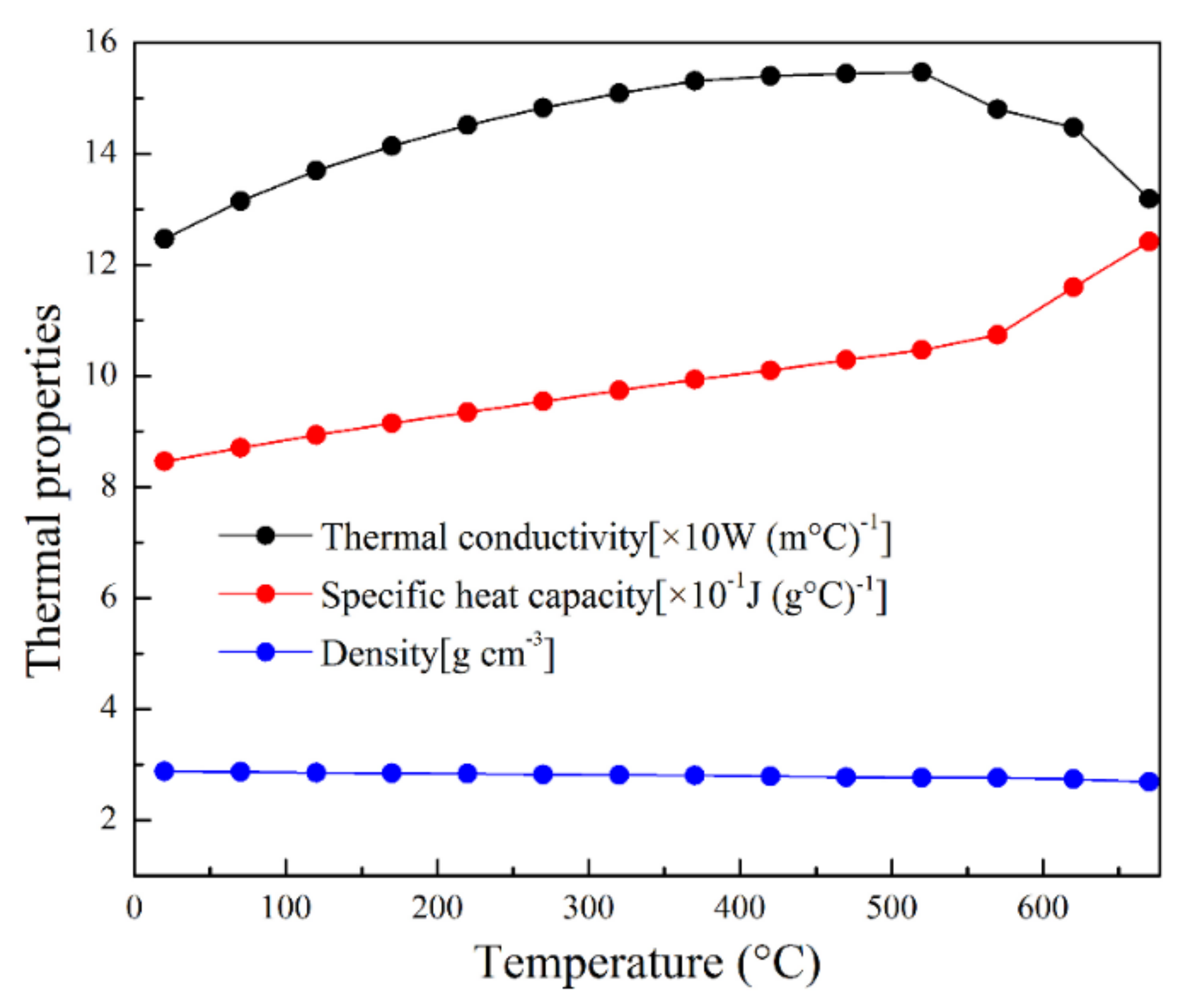
3. Numerical Simulation on Welding Temperature Field
4. Results and Discussion
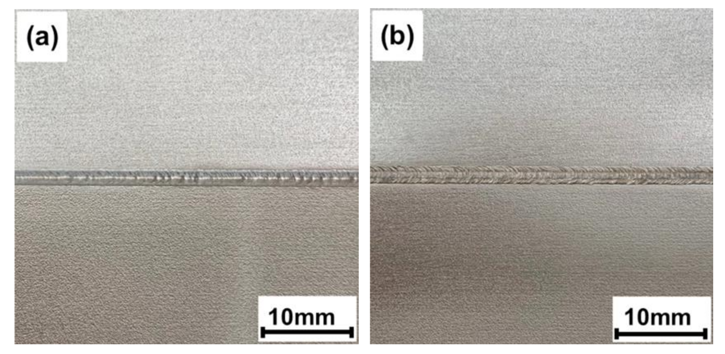
4.1. Macrograph
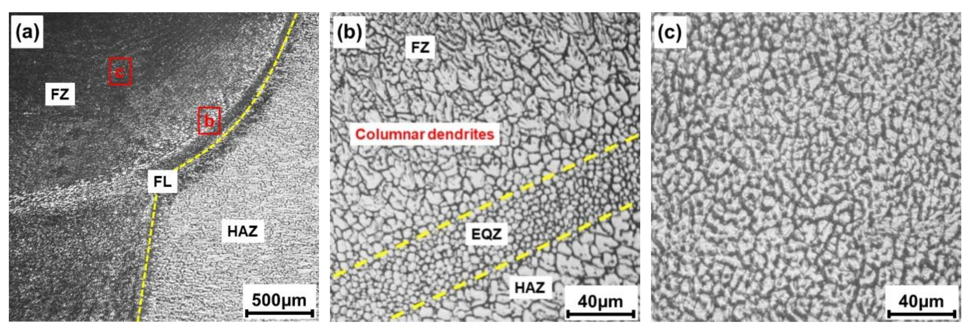
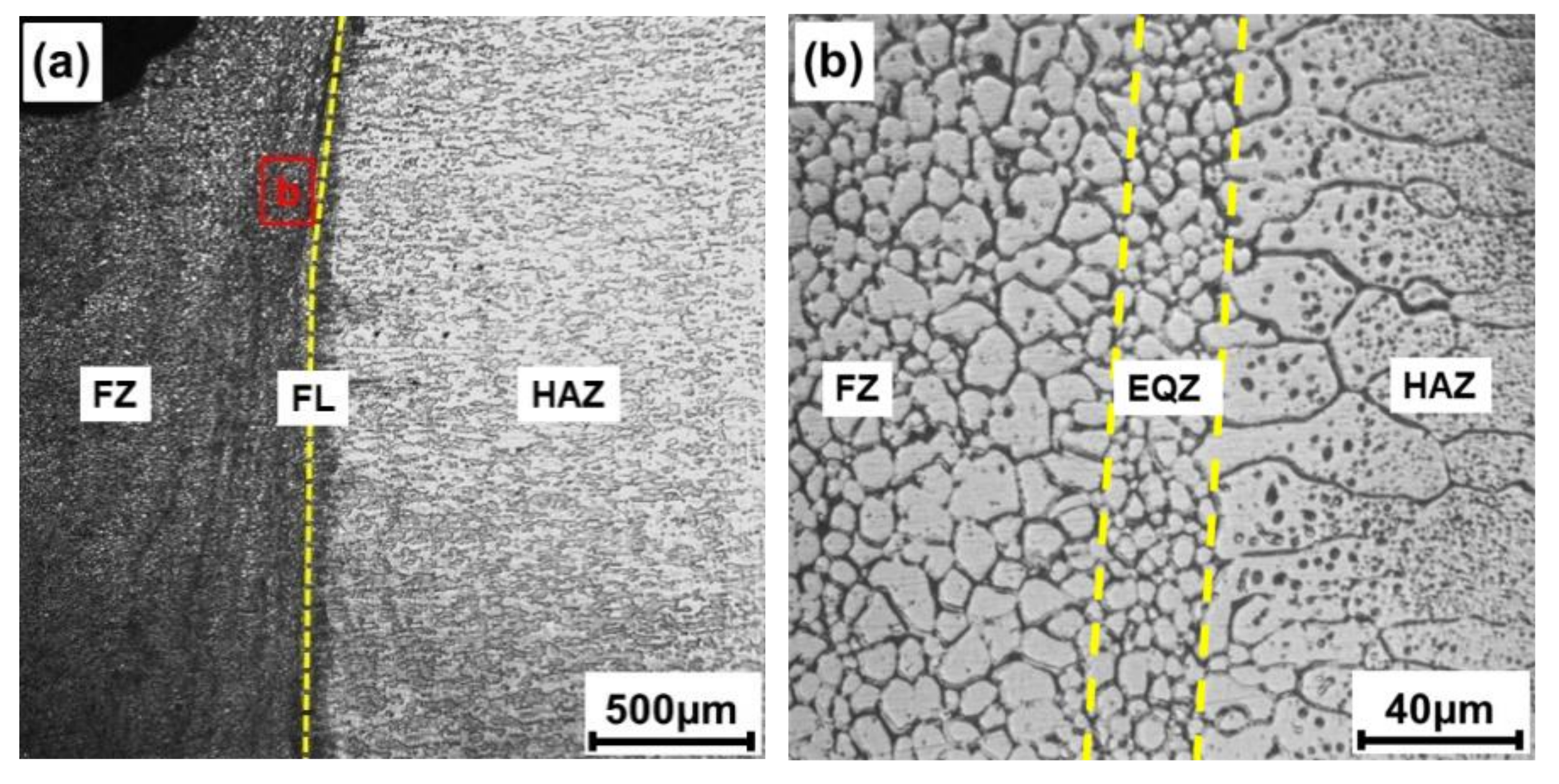
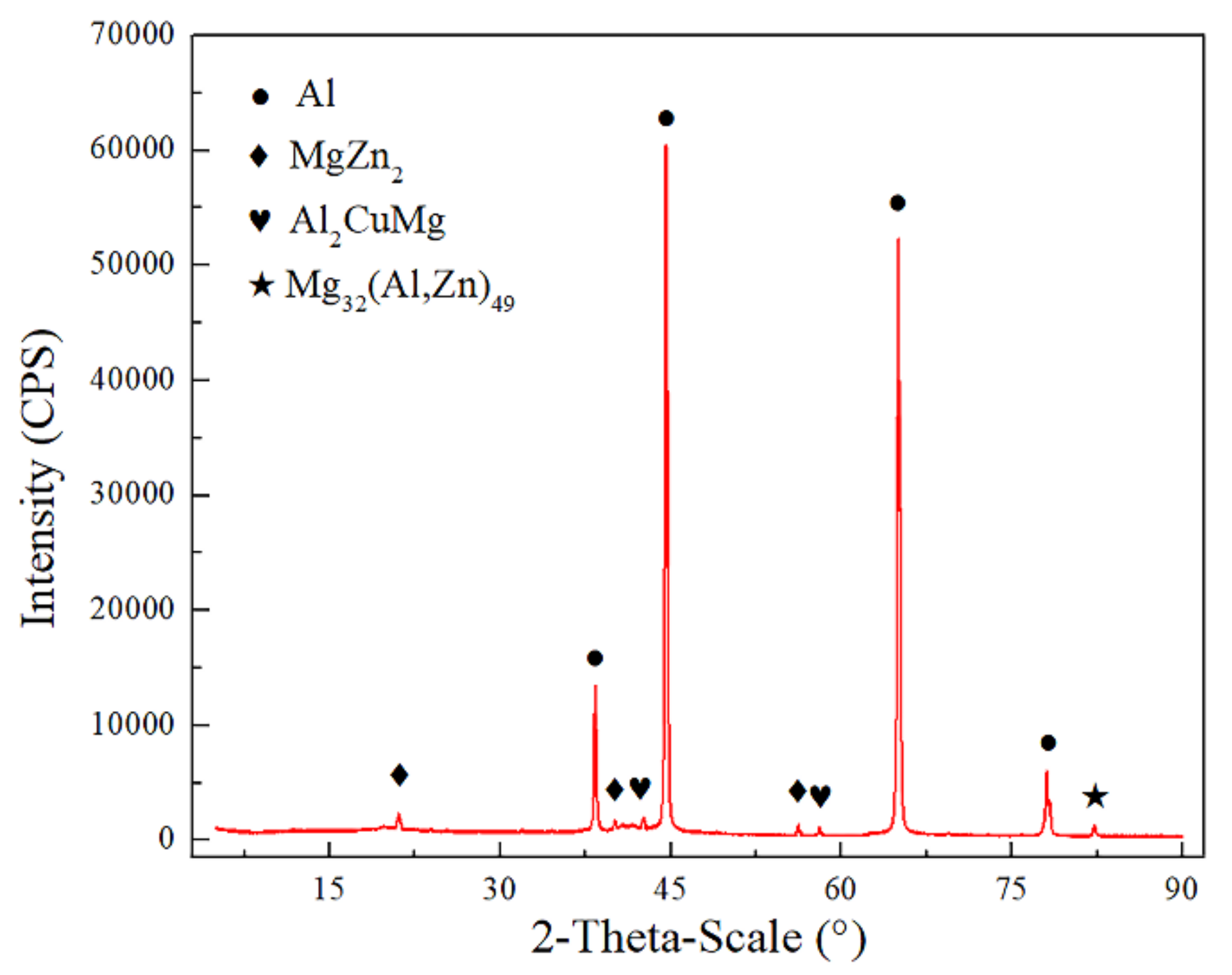
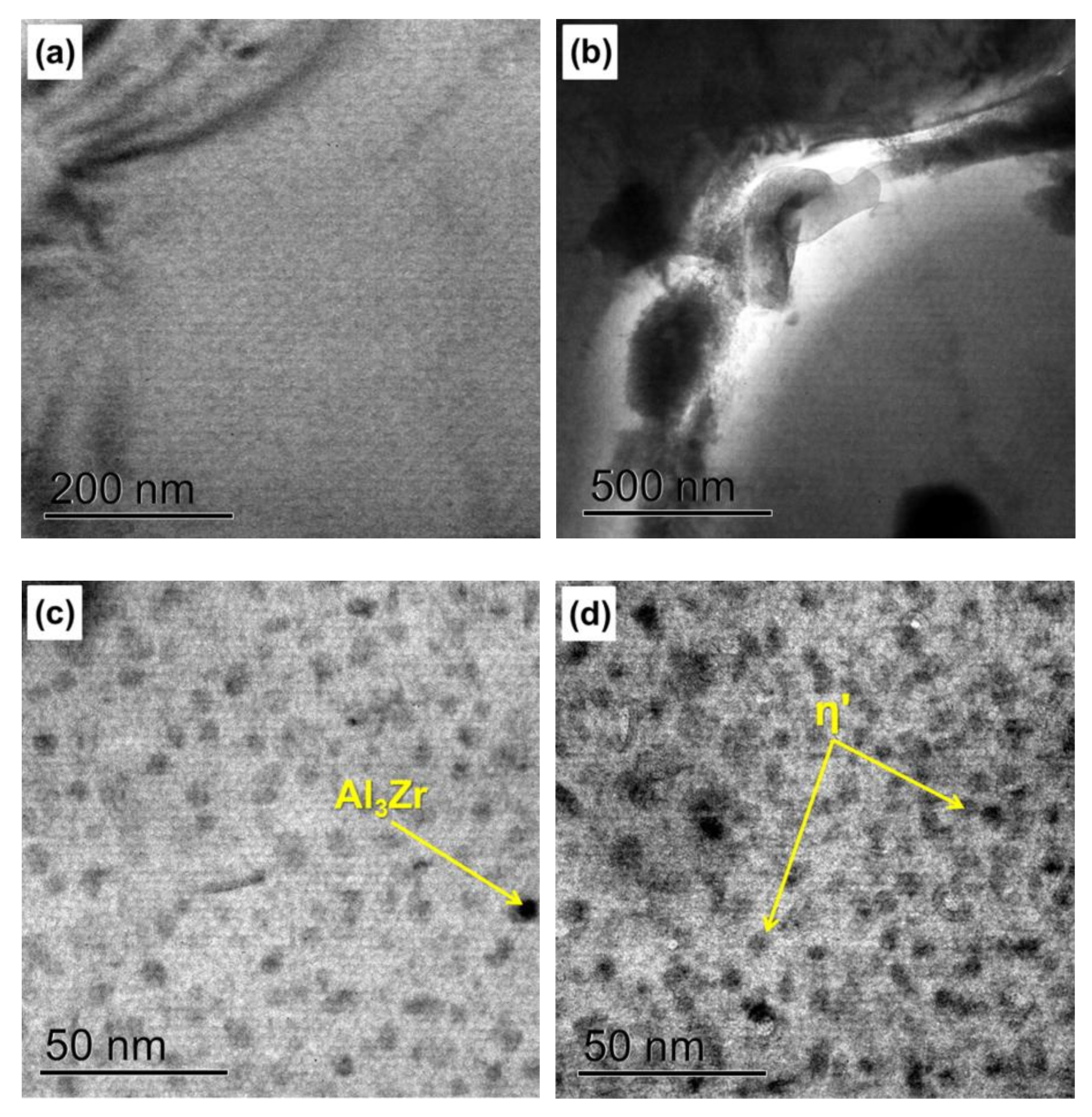
4.2. Microstructure
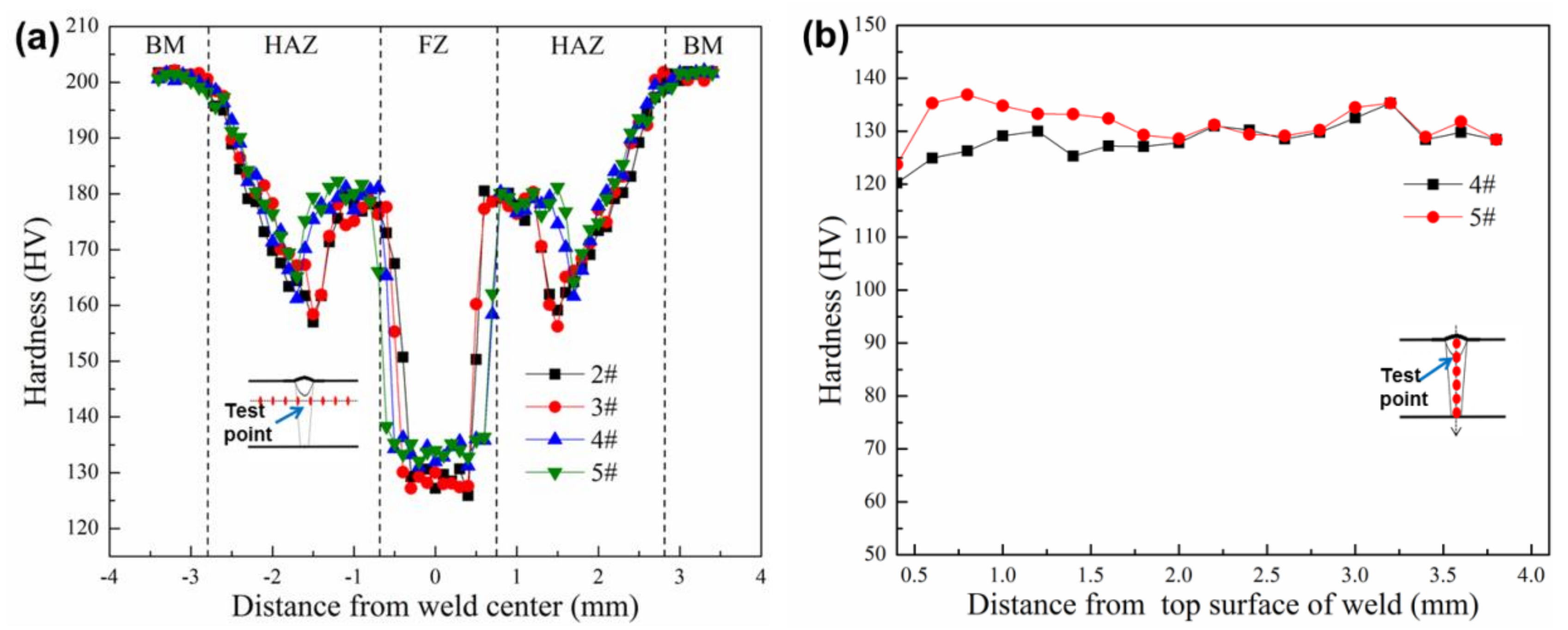
4.3. Microhardness
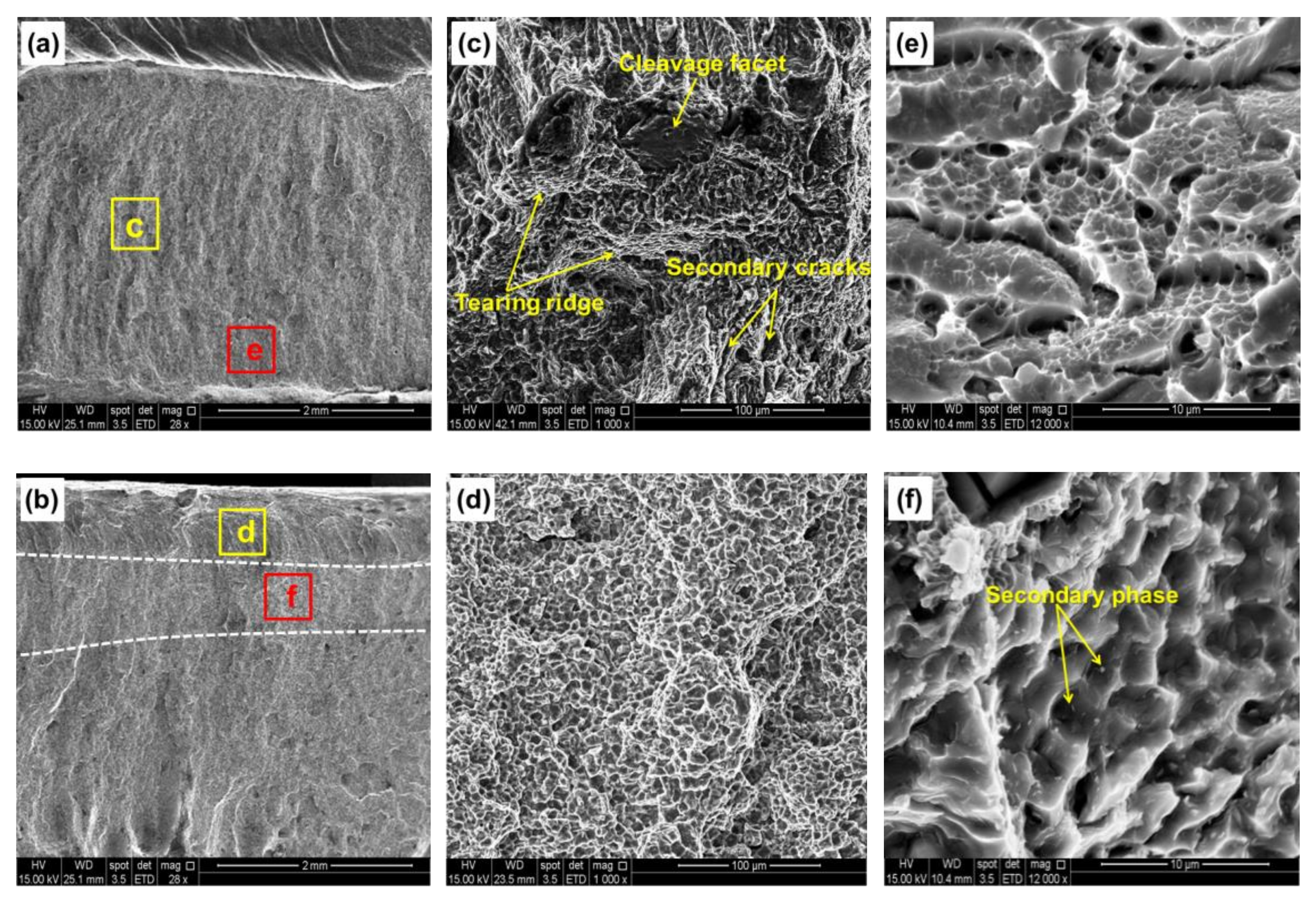
4.4. Tensile Strength and Fracture Analysis
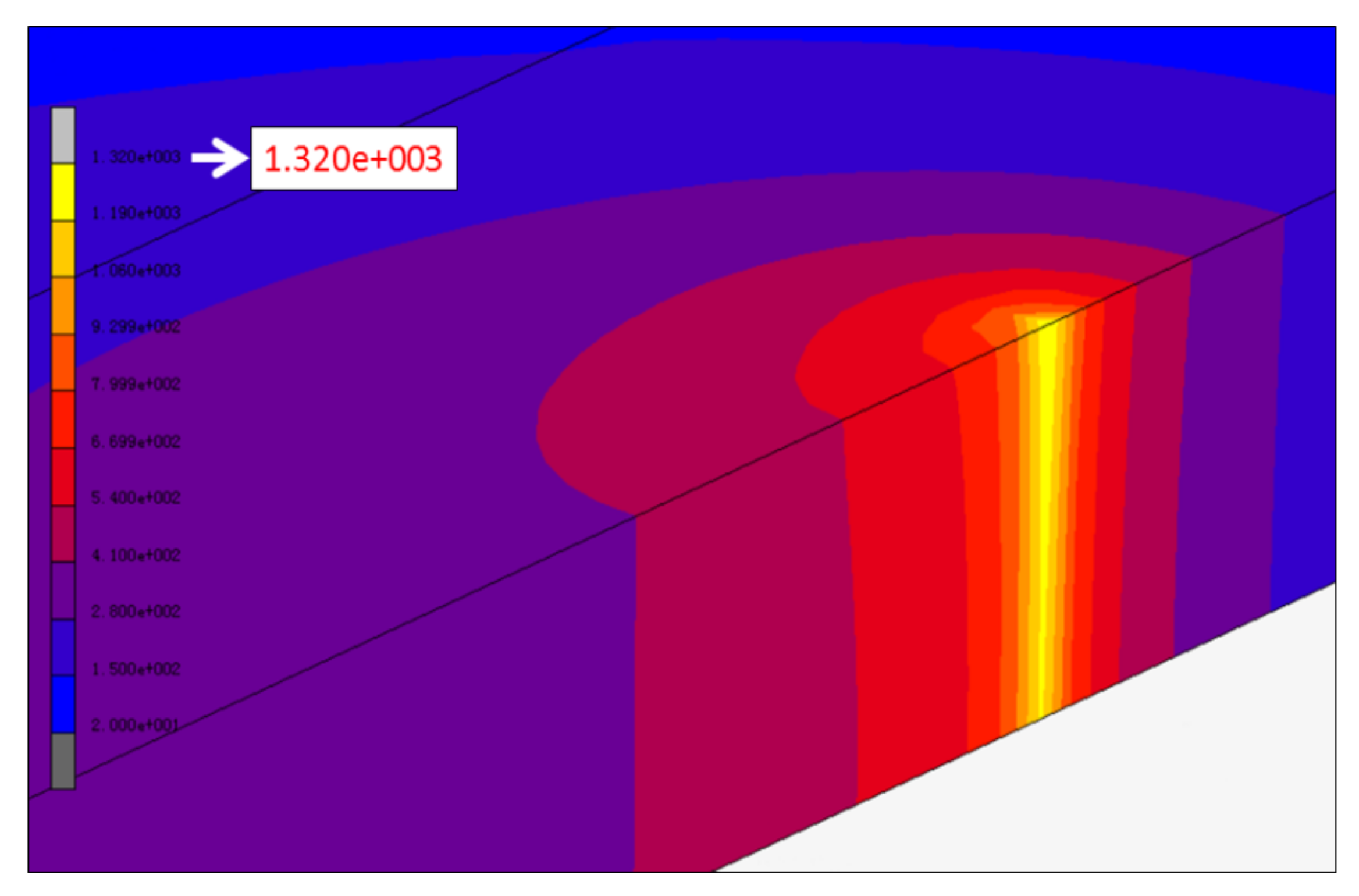
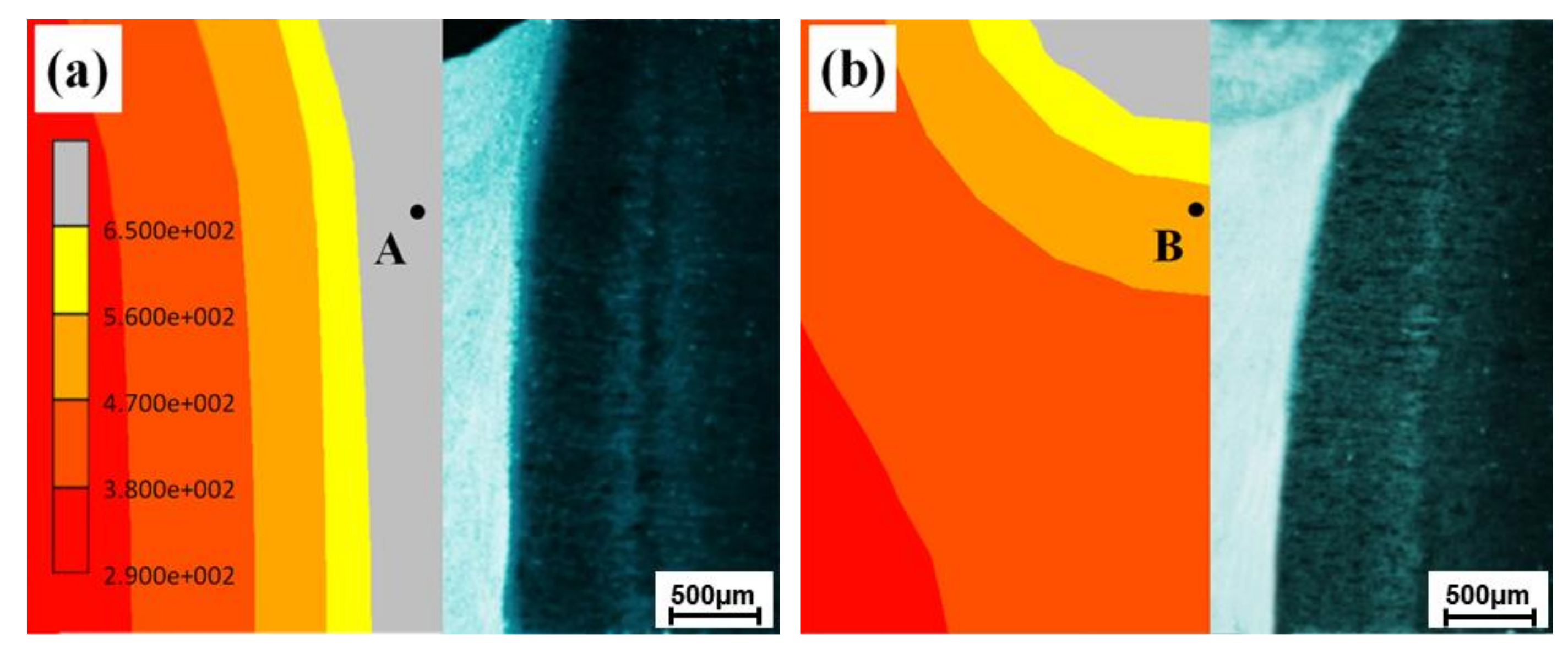
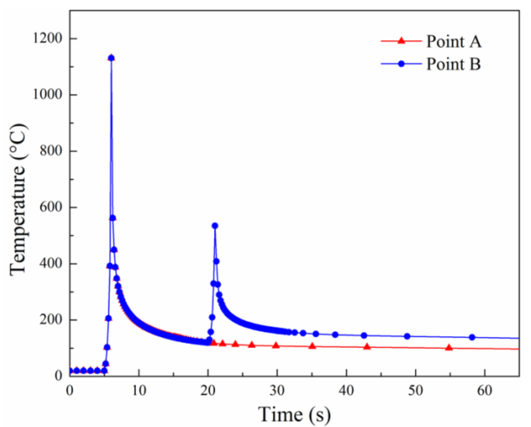
4.5. Numerical Simulation Analysis
5. Conclusions
Author Contributions
Funding
Conflicts of Interest
References
- Dursun, T.; Soutis, C. Recent developments in advanced aircraft aluminium alloys. Mater. Des. 2014, 56, 862–871. [Google Scholar] [CrossRef]
- Williams, J.C.; Starke, E.A. Progress in structural materials for aerospace systems. Acta Mater. 2003, 51, 5775–5799. [Google Scholar] [CrossRef]
- Dixit, M.; Mishra, R.S.; Sankaran, K.K. Structure-property correlations in Al 7050 and Al 7055 high-strength aluminum alloys. Mater. Sci. Eng. A 2008, 478, 163–172. [Google Scholar] [CrossRef]
- Rometsch, P.A.; Zhang, Y.; Knight, S. Heat treatment of 7xxx series aluminium alloys-some recent developments. Trans. Nonferrous Met. Soc. China 2014, 24, 2003–2017. [Google Scholar] [CrossRef]
- Mazzer, E.M.; Afonso, C.R.M.; Galano, M.; Kiminani, C.S.; Bolfarini, C. Microstructure evolution and mechanical properties of Al-Zn-Mg-Cu alloy reprocessed by spray-forming and heat treated at peak aged condition. J. Alloys Compd. 2013, 579, 169–173. [Google Scholar] [CrossRef]
- Ditta, A.; Wei, L.J.; Xu, Y.J.; Wu, S.J. Effect of hot extrusion and optimal solution treatment on microstructure and properties of spray-formed Al-11.3Zn-2.65Mg-1Cu alloy. J. Alloys Compd. 2019, 797, 558–565. [Google Scholar] [CrossRef]
- Kashaev, N.; Ventzke, V.; Çam, G. Prospects of laser beam welding and friction stir welding processes for aluminum airframe structural applications. J. Manuf. Process. 2018, 36, 571–600. [Google Scholar] [CrossRef]
- Fukuda, T. Weldability of 7000 series aluminium alloy materials. Weld. Int. 2012, 26, 256–269. [Google Scholar] [CrossRef]
- Hermann, R.; Birley, S.S.; Holdway, P. Liquation cracking in aluminium alloy welds. Mater. Sci. Eng. A 1996, 212, 247–255. [Google Scholar] [CrossRef]
- Peng, X.Y.; Cao, X.W.; Xu, G.F.; Deng, Y.; Tang, L.; Yin, Z.M. Mechanical properties, corrosion behavior, and microstructures of a MIG-welded 7020 Al alloy. J. Mater. Eng. Perform. 2016, 25, 1028–1040. [Google Scholar] [CrossRef]
- Balasubramanian, V.; Ravisankar, V.; Reddy, G.M. Influences of pulsed current welding and post weld aging treatment on fatigue crack growth behavior of AA7075 aluminium alloy joints. Int. J. Fatigue 2008, 30, 405–416. [Google Scholar] [CrossRef]
- Hassan, K.A.A.; Prangnell, P.B.; Norman, A.F.; Price, D.A.; Williams, S.W. Effect of welding parameters on nugget zone microstructure and properties in high strength aluminium alloy friction stir welds. Sci. Technol. Weld. Join. 2003, 8, 257–268. [Google Scholar] [CrossRef]
- Wang, Q.Z.; Zhao, Z.X.; Zhao, Y.; Yan, K.; Liu, C.; Zhang, H. The strengthening mechanism of spray forming Al-Zn-Mg-Cu alloy by underwater friction stir welding. Mater. Des. 2016, 102, 91–99. [Google Scholar] [CrossRef]
- Ola, O.T.; Doern, F.E. Fusion weldability studies in aerospace AA7075-T651 using high-power continuous wave laser beam techniques. Mater. Des. 2015, 77, 50–58. [Google Scholar] [CrossRef]
- Enz, J.; Riekehr, S.; Ventzke, V.; Huber, N.; Kashaev, N. Fibre laser welding of high-alloyed Al-Zn-Mg-Cu alloys. J. Mater. Process. Technol. 2016, 237, 155–162. [Google Scholar] [CrossRef]
- Enz, J.; Kumar, M.; Riekehr, S.; Ventzke, V.; Huber, N.; Kashaev, N. Mechanical properties of laser beam welded similar and dissimilar aluminum alloys. J. Manuf. Process. 2017, 29, 272–280. [Google Scholar] [CrossRef]
- Holzer, M.; Hofmann, K.; Mann, V.; Hugger, F.; Roth, S.; Schmidt, M. Change of hot cracking susceptibility in welding of high strength aluminum alloy AA7075. Phys. Procedia 2016, 83, 463–471. [Google Scholar] [CrossRef] [Green Version]
- Hu, B.; Richardson, I.M. Microstructure and mechanical properties of AA7075 (T6) hybrid Laser/GMA welds. Mater. Sci. Eng. A 2007, 459, 94–100. [Google Scholar] [CrossRef]
- Zhan, X.H.; Yu, H.S.; Feng, X.S.; Pan, P.; Liu, Z.M. A comparative study on laser beam and electron beam welding of 5A06 aluminum alloy. Mater. Res. Express 2019, 6, 056563. [Google Scholar] [CrossRef]
- Lacki, P.; Adamus, K. Numerical simulation of the electron beam welding process. Comput. Struct. 2011, 89, 977–985. [Google Scholar] [CrossRef]
- Li, Y.J.; Zhao, Y.; Li, Q.; Wu, A.P.; Zhu, R.C.; Wang, G.Q. Effects of welding condition on weld shape and distortion in electron beam welded Ti2AlNb alloy joints. Mater. Des. 2017, 114, 226–233. [Google Scholar] [CrossRef]
- Lin, D.C.; Wang, G.X.; Srivatsan, T.S. A mechanism for the formation of equiaxed grains in welds of aluminum-lithium alloy 2090. Mater. Sci. Eng. A 2003, 351, 304–309. [Google Scholar] [CrossRef]
- Senkov, O.N.; Shagiev, M.R.; Senkova, S.V.; Miracle, D.B. Precipitation of Al3(Sc,Zr) particles in an Al-Zn-Mg-Cu-Sc-Zr alloy during conventional solution heat treatment and its effect on tensile properties. Acta Mater. 2008, 56, 3723–3738. [Google Scholar] [CrossRef]
- Sha, G.; Cerezo, A. Early-stage precipitation in Al-Zn-Mg-Cu alloy (7050). Acta Mater. 2004, 52, 4503–4516. [Google Scholar] [CrossRef]
- Li, H.Y.; Gao, Z.H.; Yin, H.; Jiang, H.F.; Su, X.J.; Bin, J. Effects of Er and Zr additions on precipitation and recrystallization of pure aluminum. Scripta Mater. 2013, 68, 59–62. [Google Scholar] [CrossRef]
- Ma, T.; den Ouden, G. Softening behavior of Al-Zn-Mg alloys due to welding. Mater. Sci. Eng. A 1999, 266, 198–204. [Google Scholar] [CrossRef]
- Zhan, X.H.; Chen, J.C.; Liu, J.J.; Wei, Y.H.; Zhou, J.J.; Meng, Y. Microstructure and magnesium burning loss behavior of AA6061 electron beam welding joints. Mater. Des. 2016, 99, 449–458. [Google Scholar] [CrossRef]
- Zhao, H.; Debroy, T. Weld metal composition change during conduction mode laser welding of aluminum alloy 5182. Metall. Mater. Trans. B 2001, 32, 163–172. [Google Scholar] [CrossRef]


| Sample Number | Electron Beam Current (mA) | Focusing Current (mA) | Welding Speed (mm/s) | |
|---|---|---|---|---|
| 1 | First bead welding | 12.0 | 599 | 8 |
| Modification welding | - | - | - | |
| 2 | First bead welding | 13.5 | 599 | 9 |
| Modification welding | - | - | - | |
| 3 | First bead welding | 13.5 | 599 | 9 |
| Modification welding | 9.5 | 579 | 10 | |
| 4 | First bead welding | 15.0 | 599 | 10 |
| Modification welding | - | - | - | |
| 5 | First bead welding | 15.0 | 599 | 10 |
| Modification welding | 9.5 | 579 | 10 | |
| Sample Number | BM | Joint 1 | Joint 2 | Joint 3 | Joint 4 | Joint 5 |
|---|---|---|---|---|---|---|
| Tensile strength (MPa) | 568.0 | 267.1 | 324.7 | 348.3 | 354.6 | 371.7 |
| Elongation (%) | 8.10 | 1.19 | 1.88 | 1.91 | 1.87 | 2.12 |
Publisher’s Note: MDPI stays neutral with regard to jurisdictional claims in published maps and institutional affiliations. |
© 2020 by the authors. Licensee MDPI, Basel, Switzerland. This article is an open access article distributed under the terms and conditions of the Creative Commons Attribution (CC BY) license (http://creativecommons.org/licenses/by/4.0/).
Share and Cite
Wang, S.; Wang, Z.; Zhang, C.; Wang, Z. Numerical Simulation and Experimental Investigation on Electron Beam Welding of Spray-Formed 7055 Aluminum Alloy. Metals 2020, 10, 1392. https://doi.org/10.3390/met10101392
Wang S, Wang Z, Zhang C, Wang Z. Numerical Simulation and Experimental Investigation on Electron Beam Welding of Spray-Formed 7055 Aluminum Alloy. Metals. 2020; 10(10):1392. https://doi.org/10.3390/met10101392
Chicago/Turabian StyleWang, Shaogang, Zheng Wang, Chengcong Zhang, and Zhiguo Wang. 2020. "Numerical Simulation and Experimental Investigation on Electron Beam Welding of Spray-Formed 7055 Aluminum Alloy" Metals 10, no. 10: 1392. https://doi.org/10.3390/met10101392
APA StyleWang, S., Wang, Z., Zhang, C., & Wang, Z. (2020). Numerical Simulation and Experimental Investigation on Electron Beam Welding of Spray-Formed 7055 Aluminum Alloy. Metals, 10(10), 1392. https://doi.org/10.3390/met10101392