A New Nodal-Integration-Based Finite Element Method for the Numerical Simulation of Welding Processes


Abstract
:1. Introdution
- In Section 2, the nodal-integration-based finite element approach proposed is developed. This presentation is also taken as an occasion to clarify the relations between several classical nodal integration techniques.
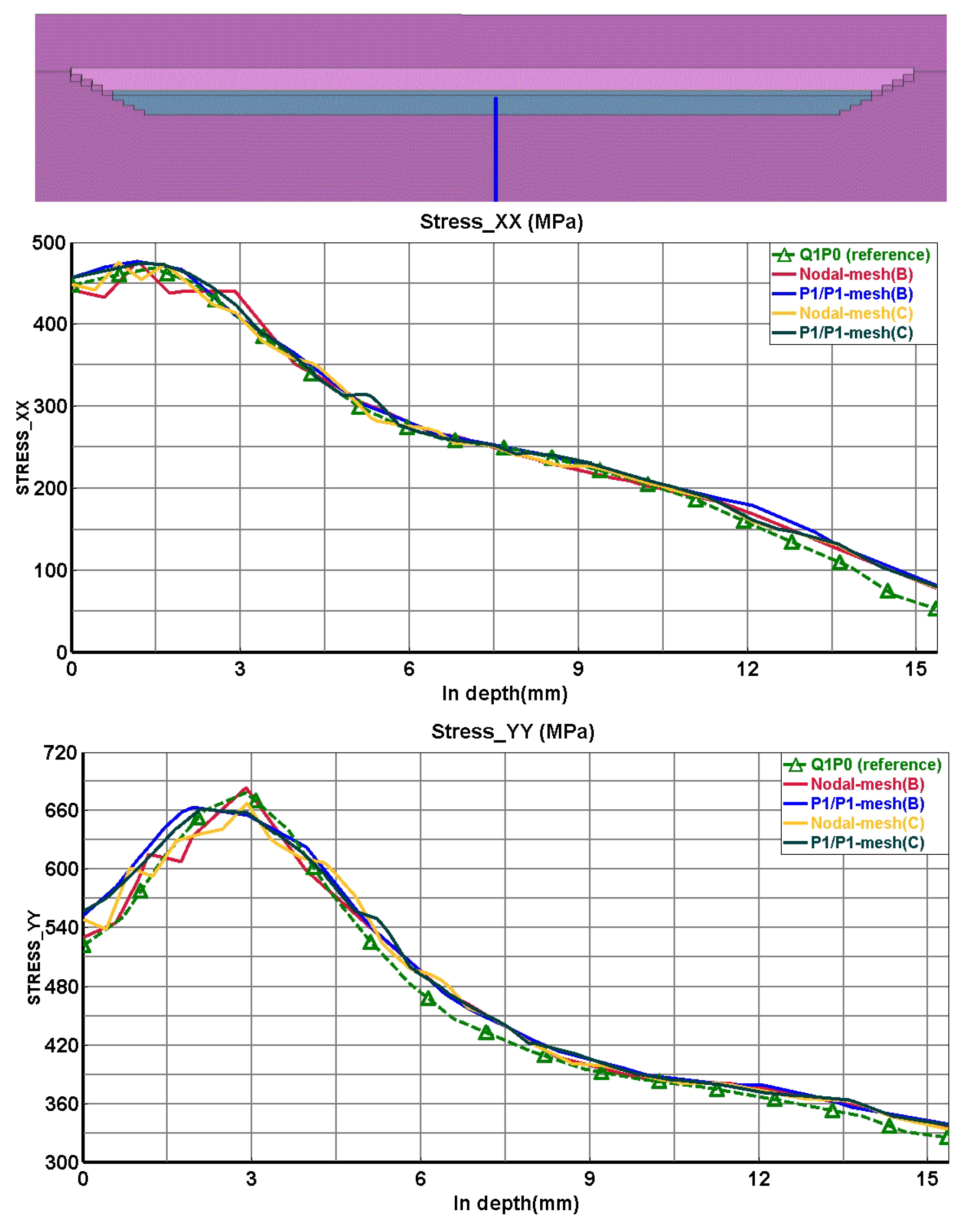
- Then, Section 3 is devoted to the application of the method to some welding simulations. The example treated is provided by Task Group 4 of the European Network on Neutron Techniques Standardization for Structural Integrity (NeT). The results are compared to those obtained with more classical finite element analyses involving elements with mixed displacement/pressure formulations: Q1P0 hexahedrons [5,8] (linear displacements and constant pressure in each element) and P1P1 tetrahedrons (linear displacements and pressure in each element) [24].
2. The Nodal-Integration-Based Finite Element Method
2.1. General Principles
2.2. Definition of Nodal Domains and Nodal Strains
2.3. Definition of Nodal Thermal Strains
2.4. Calculation of Stresses and Internal Variables
2.5. Benefits and Drawbacks of the Nodal Approach
- The restriction to linear triangular (in 2D) or tetrahedral (in 3D) meshes is compatible with the use of the standard automatic meshing tools available nowadays;
- Volumetric locking, for incompressible or nearly incompressible media, is eliminated by the very principle of the method, which places the integration points at the nodes carrying the degrees of freedom;
- Transfer of quantities from one mesh to another (if remeshing is required) also becomes easier. Indeed, with the classical FEM, such a transfer requires, just like the plotting of contours, a preliminary extrapolation of these quantities from the Gauss points to the nodes of the first mesh, which again is made unnecessary by the nodal approach;
- If the elements become too distorted near one or several node(s), local remeshing may be achieved by redefining the elements without moving the nodes, thus circumventing any transfer of quantities;
- The size of the results files is greatly reduced, thus permitting to consider larger meshes. This advantage arises from the storage of physical quantities at the nodes instead of the Gauss points, combined with the fact that at least for big structures, the total number of nodes is generally much lower than the total number of Gauss points. (In the case of first-order tetrahedral meshes, the ratio is of the order of .)
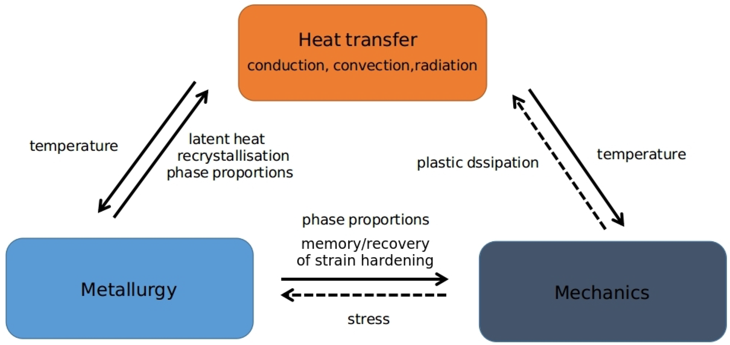
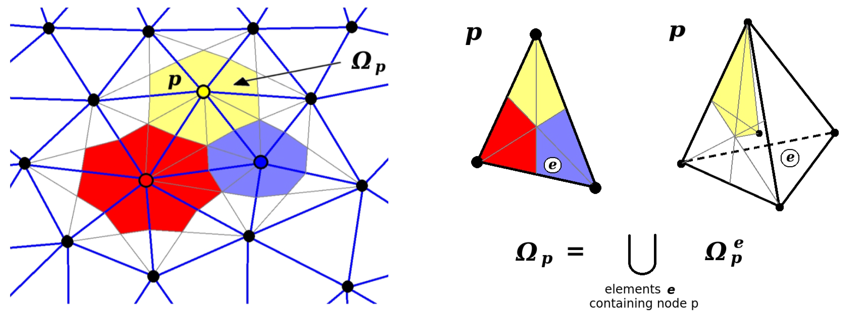
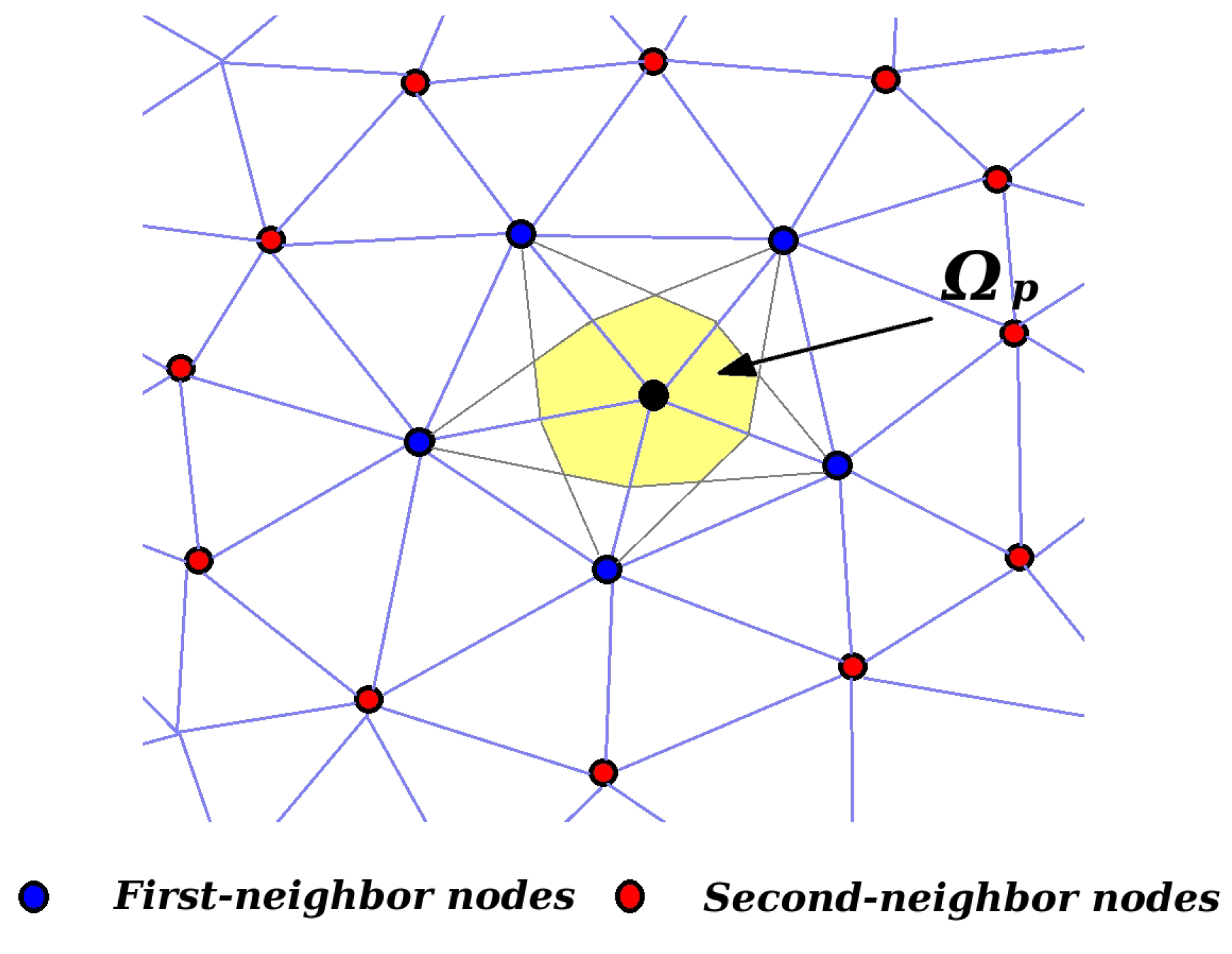
- One shortcoming arises from the very definition of the nodal strains (Equation (8)). The strain tensor at node p depends on the displacements at all nodes belonging to elements containing node p (first-neighbor nodes). This introduces couplings between first-neighbor nodes in the so-called “-matrix” connecting the strain tensor at a given point to the displacements of nodes, and thus couplings between second-neighbor nodes in the global tangent matrix (Figure 3). In contrast, in the classical FEM, couplings in the tangent matrix arise only between first-neighbor nodes. This must induce an increase of the computation time within the nodal approach. In practice, however, this disadvantage is more than compensated by the solving of constitutive equations at the nodes, which are much less numerous than the Gauss points where these equations are solved in the classical FEM;
- Another drawback arises from the possible presence, in some cases, of “hourglass” modes—that is, ensembles of nodal displacements generating a strain field with zero elastic energy, although not defining a rigid-body motion. To overcome this shortcoming, Puso et al. [25,26] proposed to modify the weak form of the equilibrium equations in the following way:where is a small, positive “stabilization parameter”, and denotes the stress tensor calculated assuming a purely elastic behavior. In the expression between big parentheses, the first integral is calculated using nodal integration, while Gaussian integration is used for the second.
3. Application to Some Welding Simulation
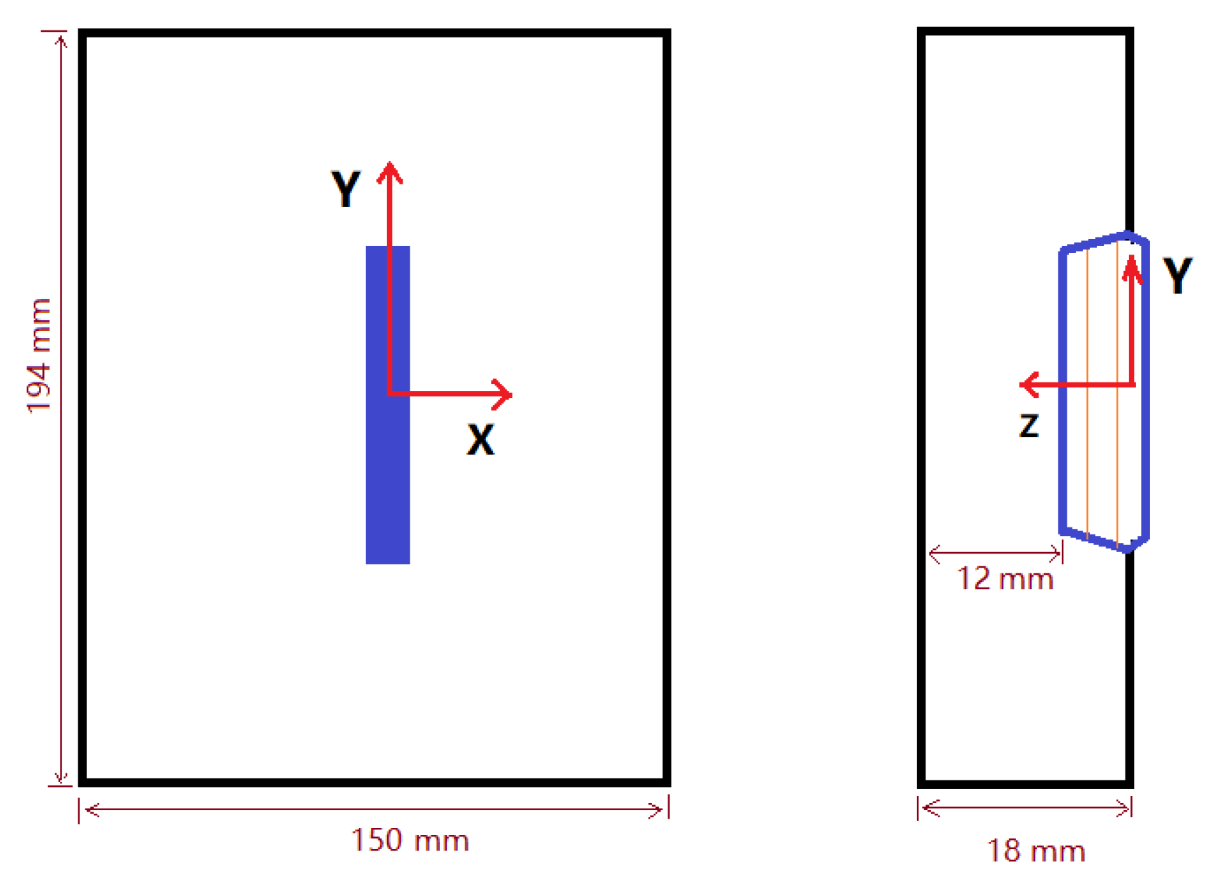
3.1. Benchmark Model
- Validation of numerical results versus experiments. What is essentially validated in this way is the quality of the physical model(s) used in the simulation: for instance, for elastoplastic problems, the relevance of the modeling of strain hardening phenomena (isotropic, kinematic or mixed istropic/kinematic model);
- Validation of the numerical results through comparison with results obtained with other numerical methods (including, if possible, one acceptable as a reliable “reference”). What is tested in that way is the quality of the numerical solution obtained with the method investigated, the physical model(s) being given and fixed.
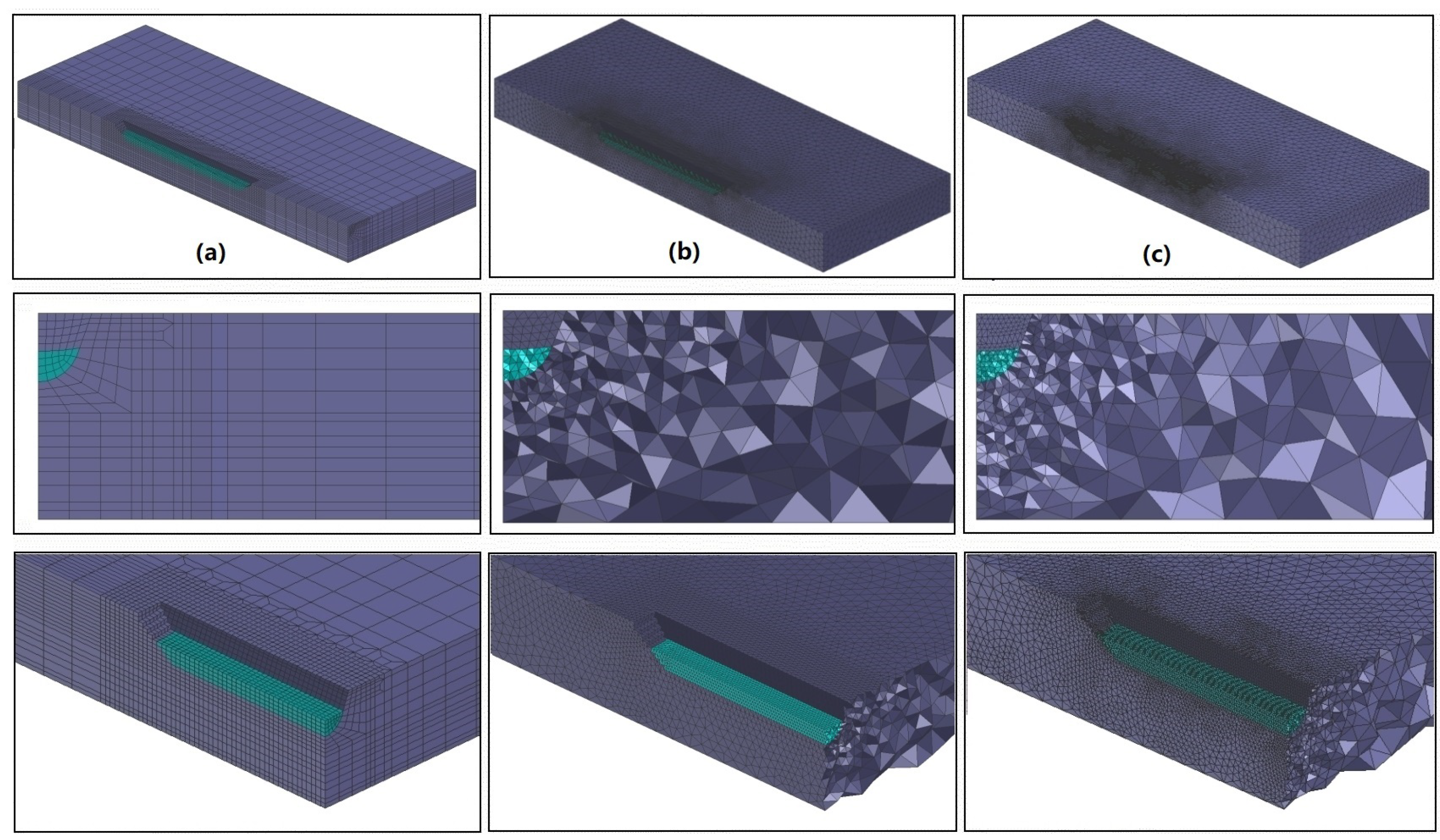
3.2. Meshes
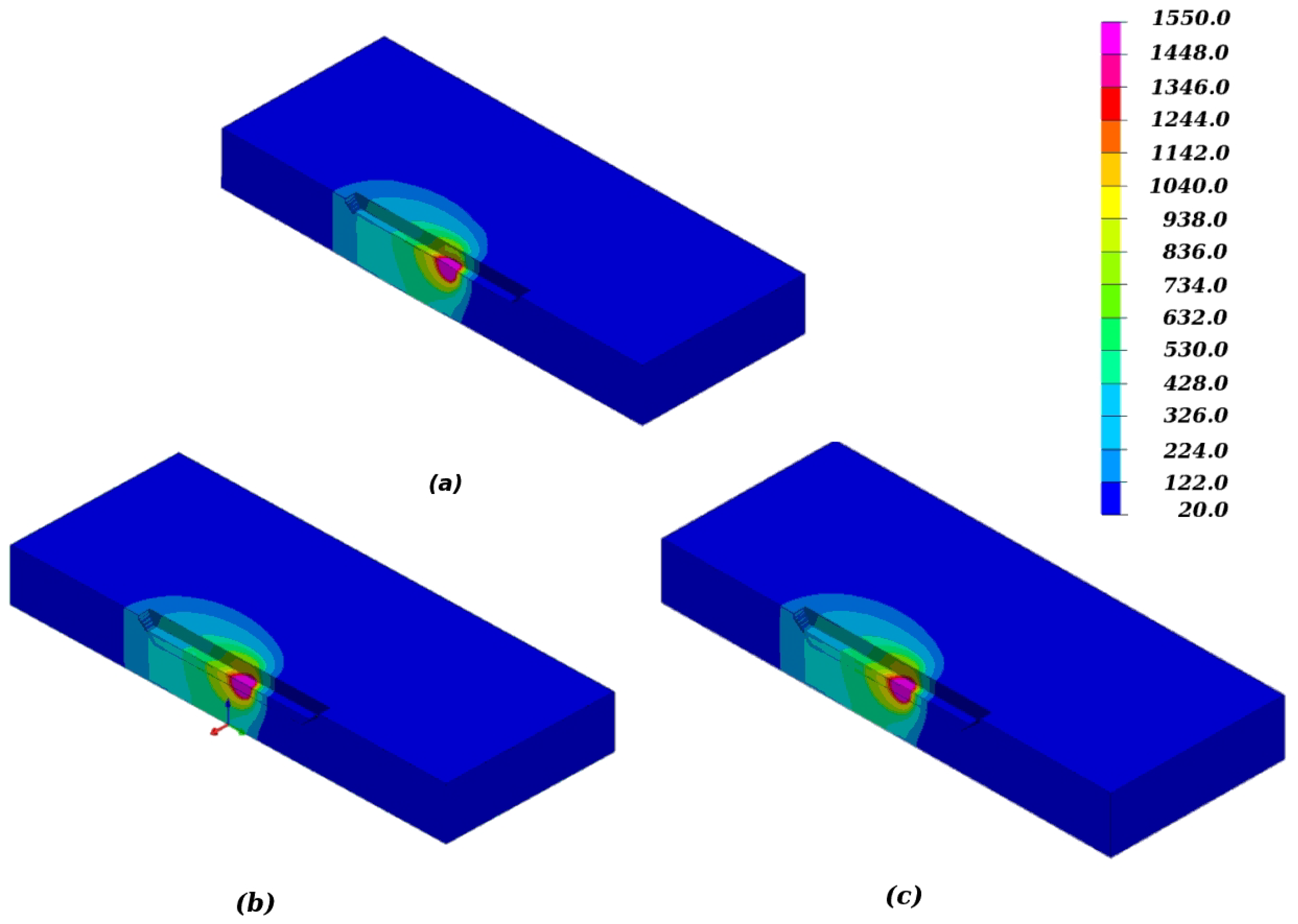
3.3. Thermal Simulations
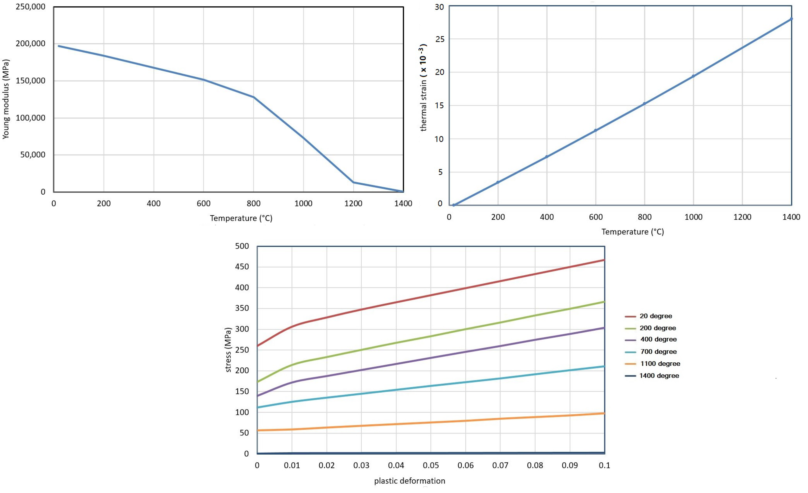
3.4. Mechanical Simulations
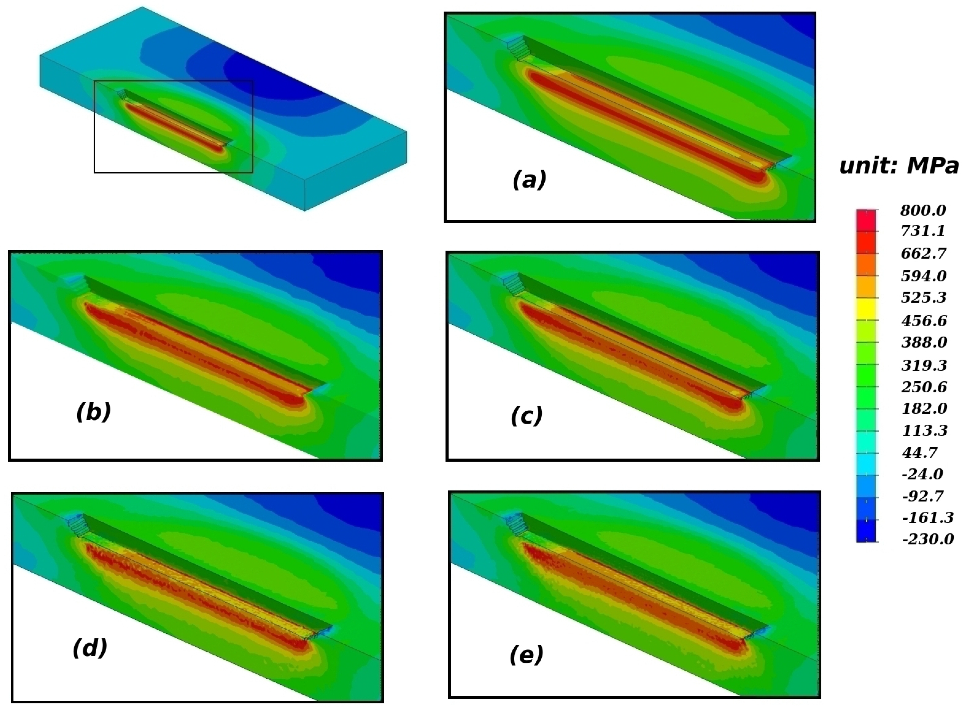
- Since in the simulations just presented, the nodal thermal strains were simply evaluated from the nodal temperatures, another possible remedy consists of using the other two options presented in Section 2.3 for the calculation of these thermal strains. Figure 10 compares the distributions of the residual mean stress (pressure) obtained with the three different options, on the cruder mesh B. The comparison clearly shows that the stress distribution obtained is slightly smoother when the thermal strain at a given node is obtained from some average of the temperature over all the subvolumes (option 2) or elements (option 3) containing this node, instead of simply the nodal temperature there (option 1). Option 2 (using an average of the temperature over the subvolumes containing the node considered), which warrants a smoother stress distribution while being logically consistent with the SCNI approach of Chen et al. [19,20,21], is therefore recommended;
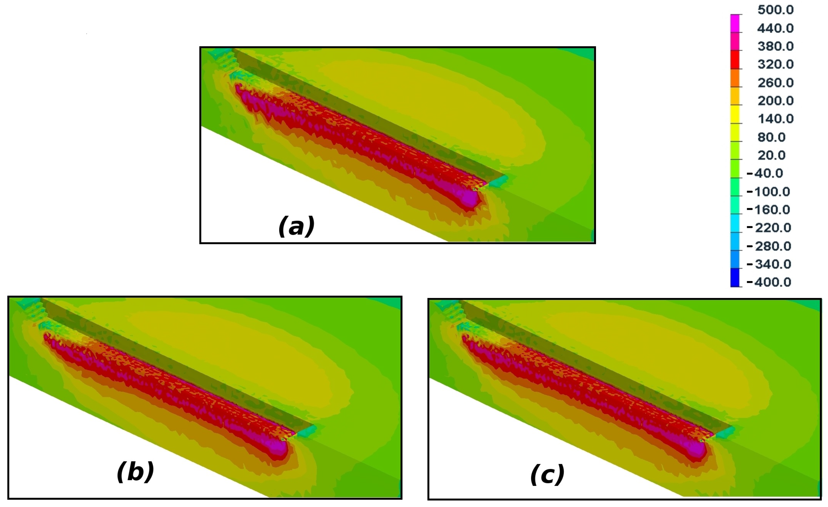
- Finally, one may note that the stress distributions provided by the standard FEM are basically obtained from average values of the stress components in the elements (before these values are transported to the nodes for the plot), rather than from truly discrete values at Gauss points; this means that with the classical FEM, more confidence is put in volume values than point values. (It is well-known, for instance, that for quadratic subintegrated elements, stress values at Gauss points are much less reliable than average values in elements.) Therefore, it seems logical for consistency reasons, when using the nodal approach, to first average the stresses in the elements before plotting their distribution in the same way as with the standard FEM. (The suggestion was first made by Puso et al. [25].) Figure 11 compares the distribution of the mean stress (pressure) obtained in this way to the reference distribution obtained with the classical FEM with Q1P0 elements. The slight smoothing resulting from the suggested averaging of stresses over elements may be seen to lead to some stress distribution of quality comparable to that of the reference.
4. Conclusions
Author Contributions
Funding
Acknowledgments
Conflicts of Interest
References
- Radaj, D. Heat Effects of Welding; Springer: Berlin, Germany, 1992; ISBN 978-3-642-48640-1. [Google Scholar]
- Leblond, J.-B.; Pont, D.; Devaux, J.; Bru, D.; Bergheau, J.-M. Metallurgical and mechanical consequences of phase transformations in numerical simulations of welding processes. In Modeling in Welding, Hot Powder Forming and Casting; Karlsson, L., Ed.; ASM International: Materials Park, OH, USA, 1997; Chapter 4; pp. 61–89. [Google Scholar]
- Bergheau, J.-M. Thermo-Mechanical Industrial Processes: Modeling and Numerical Simulation; Karlsson, L., Ed.; ISTE Ltd.: London, UK; John Wiley & Sons, Inc.: Hoboken, NJ, USA, 2014; ISBN 978-1-84821-358-6. [Google Scholar] [CrossRef]
- Feulvarch, E.; Robin, V.; Bergheau, J.-M. Thermometallurgical and mechanical modelling of welding—Application to multipass dissimilar metal girth welds. Sci. Technol. Weld. Join. 2011, 16, 221–226. [Google Scholar] [CrossRef]
- Nagtegaal, J.C.; Parks, D.M.; Rice, J.R. On numerically accurate finite element solutions in the fully plastic range. Comput. Meth. Appl. Mech. Eng. 1974, 4, 153–177. [Google Scholar] [CrossRef]
- Hughes, T.J.R. The Finite Element Method: Linear Static and Dynamic Finite Element Analysis; Prentice-Hall: Upper Saddle River, NJ, USA, 1987. [Google Scholar]
- Bathe, K. Finite Element Procedure; Prentice-Hall: Upper Saddle River, NJ, USA, 1996. [Google Scholar]
- Brezzi, F.; Fortin, M. Mixed and Hybrid Finite Element Methods; Springer: Berlin, Germany, 1991. [Google Scholar]
- Arnold, D.N.; Brezzi, F.; Fortin, M. A stable finite element for the Stokes equations. Calcolo 1984, 21, 337–344. [Google Scholar] [CrossRef]
- Heuzé, T.; Amin-El-Sayed, H.; Leblond, J.B.; Bergheau, J.M. Benchmark tests based on the Couette viscometer—II: Thermo-elasto-plastic solid behaviour in small and large strains. Comput. Math. Appl. 2014, 67, 1482–1496. [Google Scholar] [CrossRef]
- Bonet, J.; Burton, J. A simple average nodal pressure tetrahedral element for incompressible and nearly incompressible dynamic explicit applications. Comm. Numer. Meth. Eng. 1998, 14, 437–449. [Google Scholar] [CrossRef]
- Dohrmann, C.R.; Heinstein, M.W.; Jung, J.; Key, S.W.; Witkowski, W.R. Node-based uniform strain elements for three-node triangular and four-node tetrahedral meshes. Int. J. Numer. Meth. Eng. 2000, 47, 1549–1568. [Google Scholar] [CrossRef]
- Bonet, J.; Marriott, H.; Hassan, O. An averaged nodal deformation gradient linear tetrahedral element for large strain explicit dynamic applications. Comm. Numer. Meth. Eng. 2001, 17, 551–561. [Google Scholar] [CrossRef]
- Castellazzi, G.; Artioli, E.; Krysl, P. Linear tetrahedral element for problems of plastic deformation. Meccanica 2015, 50, 3069–3086. [Google Scholar] [CrossRef]
- Krysl, P.; Kagey, H. Reformulation of nodally integrated continuum elements to attain insensitivity to distortion. Int. J. Numer. Meth. Eng. 2012, 90, 805–818. [Google Scholar] [CrossRef]
- Krysl, P.; Zhu, B. Locking-free continuum displacement finite elements with nodal integration. Int. J. Numer. Meth. Eng. 2008, 76, 1020–1043. [Google Scholar] [CrossRef]
- Liu, G.R.; Nguyen-Thoi, T.; Nguyen-Xuan, H.; Lam, K.Y. A node-based smoothed finite element method (NS-FEM) for upper bound solutions to solid mechanics problems. Comput. Struct. 2009, 87, 14–26. [Google Scholar] [CrossRef]
- Nguyen-Thoi, T.; Vu-Do, H.C.; Rabczuk, T.; Nguyen-Xuan, H. A node-based smoothed finite element method (NS-FEM) for upper bound solution to visco-elastoplastic analyses of solids using triangular and tetrahedral meshes. Comput. Methods Appl. Mech. Eng. 2010, 199, 3005–3027. [Google Scholar] [CrossRef]
- Chen, J.S.; Wu, C.T.; Yoon, S.; You, Y. A stabilized conforming nodal integration for Galerkin mesh-free methods. Int. J. Numer. Meth. Eng. 2001, 50, 435–466. [Google Scholar] [CrossRef]
- Chen, J.S.; Yoon, S.; Wu, C.T. Non-linear version of stabilized conforming nodal integration for Galerkin mesh-free methods. Int. J. Numer. Meth. Eng. 2002, 53, 2587–2615. [Google Scholar] [CrossRef]
- Elmer, W.; Chen, J.S.; Puso, M.; Taciroglu, E. A stable, meshfree, nodal integration method for nearly incompressible solids. Finite Elem. Anal. Des. 2012, 51, 81–85. [Google Scholar] [CrossRef]
- Quak, W.; van den Boogaard, A.H.; González, D.; Cueto, E. A comparative study on the performance of meshless approximations and their integration. Comput. Mech. 2011, 48, 121–137. [Google Scholar] [CrossRef] [Green Version]
- Canales, D.; Leygue, A.; Chinesta, F.; Alfaro, I.; González, D.; Cueto, E.; Feulvarch, E.; Bergheau, J.M. In-plane/out-of-plane separated representations of updated Lagrangian descriptions of viscoplastic flow models in plate domains. Comptes Rendus Méc. 2016, 344, 225–235. [Google Scholar] [CrossRef] [Green Version]
- Feulvarch, E.; Roux, J.C.; Bergheau, J.M.; Gilles, P. A stable P1/P1 finite element for finite strain von Mises elasto-plasticity. Comput. Meth. Appl. Mech. Eng. 2017, 324, 537–545. [Google Scholar] [CrossRef]
- Puso, M.A.; Solberg, J. A stabilized nodally integrated tetrahedral. Int. J. Numer. Meth. Eng. 2006, 67, 841–867. [Google Scholar] [CrossRef]
- Puso, M.A.; Chen, J.S.; Zywicz, E.; Elmer, W. Meshfree and finite element nodal integration method. Int. J. Numer. Meth. Eng. 2008, 74, 416–446. [Google Scholar] [CrossRef]
- Software SYSWELDTM version 21, Reference Analysis Manual, Released: 2019; ESI-Group: Lyon, France, 2019.
- Ohms, C.; Martins, R.V.; Uca, O.; Youtsos, A.G.; Bouchard, P.J.; Smith, M.; Keavey, M.; Bate, S.K.; Gilles, P.; Wimpory, R.C.; et al. The European network on neutron techniques standardization for structural intergrity (NeT). In Proceedings of the ASME 2008 Pressure Vessels and Piping Conference (PVP2008), Chicago, IL, USA, 27–31 July 2008; pp. 625–637. [Google Scholar] [CrossRef]
- Xu, J.; Gilles, P. Numerical simulation of a single bead on plate and three pass slot welds in austenitic stainless steel. In Proceedings of the ASME 2011 Pressure Vessels and Piping Conference (PVP2011), Baltimore, MD, USA, 17–21 July 2011; pp. 1187–1193. [Google Scholar] [CrossRef]
- Software Visual-MeshTM Version 15.5; ESI-Group: Lyon, France, 2019.
- Lindgren, L.-E. Numerical modelling of welding. Comput. Meth. Appl. Mech. Eng. 2006, 195, 6710–6736. [Google Scholar] [CrossRef]
- Anca, A.; Cardona, A.; Risso, J.; Fachinotti, V.D. Finite element modeling of welding processes. Appl. Math. Model. 2011, 35, 688–707. [Google Scholar] [CrossRef]
- Duranton, P.; Devaux, J.; Robin, V.; Gilles, P.; Bergheau, J.-M. 3D modelling of multipass welding of a 316 L stainless steel pipe. J. Mater. Process. Technol. 2004, 153–154, 457–463. [Google Scholar] [CrossRef]


| Puissance (W) | Energy () | Traveling Speed () | Bead Length () | Interpass Temperature () | |
|---|---|---|---|---|---|
| Pass 1 | 1650 | 1300 | 1.27 | 74 | 22 |
| Pass 2 | 1463 | 1150 | 1.27 | 76 | 58 |
| Pass 3 | 1388 | 1100 | 1.27 | 82 | 60 |
| Element & Mesh | Mesh A | Mesh B | Mesh C |
|---|---|---|---|
| Q1P0 element | Yes | - | - |
| P1P1 element | - | Yes | Yes |
| Nodal integration | - | Yes | Yes |
| Type of Simulation & Resources | CPU Time (h) | RAM (Go) | Disk Space Per Time Step (Mo) |
|---|---|---|---|
| Q1P0 mesh (A) | 0.96 | 0.47 | 46.7 |
| P1P1 mesh (B) | 2.27 | 0.51 | 29.9 |
| P1P1 mesh (C) | 4.02 | 0.76 | 41.5 |
| Nodal mesh (B) | 2.07 | 0.97 | 7.1 |
| Nodal mesh (C) | 3.37 | 1.5 | 9.9 |
Publisher’s Note: MDPI stays neutral with regard to jurisdictional claims in published maps and institutional affiliations. |
© 2020 by the authors. Licensee MDPI, Basel, Switzerland. This article is an open access article distributed under the terms and conditions of the Creative Commons Attribution (CC BY) license (http://creativecommons.org/licenses/by/4.0/).
Share and Cite
Jia, Y.; Bergheau, J.-M.; Leblond, J.-B.; Roux, J.-C.; Bouchaoui, R.; Gallée, S.; Brosse, A. A New Nodal-Integration-Based Finite Element Method for the Numerical Simulation of Welding Processes. Metals 2020, 10, 1386. https://doi.org/10.3390/met10101386
Jia Y, Bergheau J-M, Leblond J-B, Roux J-C, Bouchaoui R, Gallée S, Brosse A. A New Nodal-Integration-Based Finite Element Method for the Numerical Simulation of Welding Processes. Metals. 2020; 10(10):1386. https://doi.org/10.3390/met10101386
Chicago/Turabian StyleJia, Yabo, Jean-Michel Bergheau, Jean-Baptiste Leblond, Jean-Christophe Roux, Raihane Bouchaoui, Sebastien Gallée, and Alexandre Brosse. 2020. "A New Nodal-Integration-Based Finite Element Method for the Numerical Simulation of Welding Processes" Metals 10, no. 10: 1386. https://doi.org/10.3390/met10101386