Review

A Comparison Between Semisolid Casting Methods for Aluminium Alloys

by
Anders E. W. Jarfors
Department of Materials and Manufacturing, School of Engineering, Jönköping University, Box 1026, 551 11 Jönköping, Sweden
Metals 2020, 10(10), 1368; https://doi.org/10.3390/met10101368
Submission received: 18 September 2020 / Revised: 5 October 2020 / Accepted: 8 October 2020 / Published: 13 October 2020
(This article belongs to the Special Issue Lightweight Metals: Process, Microstructure, and Properties)

Abstract

:
Semisolid casting of aluminium alloys is growing. For magnesium alloys, Thixomoulding became the dominant process around the world. For aluminium processing, the situation is different as semisolid processing of aluminium is more technically challenging than for magnesium. Today three processes are leading the process implementation, The Gas-Induced Superheated-Slurry (GISS) method, the RheoMetal process and the Swirling Enthalpy Equilibration Device (SEED) process. These processes have all strengths and weaknesses and will fit a particular range of applications. The current paper aims at looking at the strengths and weaknesses of the processes to identify product types and niche applications for each process based on current applications and development directions taken for these processes.

1. Introduction

Semisolid casting has developed strongly over the years with many different processes being developed. In general, all these processes can be divided into two main routes for semisolid casting, thixocasting and rheocasting [1]. The principal difference between these is that the Thixocasting route involves the reheating a material into a semisolid state. Rheocasting, on the other hand, utilises a standard melt, cooled into a semisolid state. Thixocasting gained, through Thixomoulding a wide commercial implementation for Mg alloys. [2] Thixocasting requires special pretreatments of the billets to be reheated and struggles with material and process cost for aluminium. Rheocasting does not have the same difficulties with process cost, not materials costs as standard alloys can be used and are now expanding strongly for aluminium [3]. Driven by the needs to produce high quality, lower costs parts for primarily the electronics and automotive industries, several different rheocasting processes have been developed. Examples of these processes are the New Rheocasting process (NRC) [4,5], Sub-Liquidus Casting process (SLC) [6,7], Semisolid Rheo Casting process (SSR) [8,9,10], rheo-die casting [7], Gas-Induced Superheated-Slurry process (GISS) s [11], Rapid-S or the RheoMetal process [8], Swirling Enthalpy Equilibration Device process (SEED) [12,13,14,15,16,17,18] and many more. The leading processes with the strongest industrialisation are the GISS, RheoMetal and SEED processes [3].
The processes GISS, RheoMetal and SEED, can be differentiated based on the solid fraction of the solid fraction entering the shot sleeve/die cavity. GISS uses the lowest fraction and SEED uses the highest. The quality of a slurry also depends on the morphology determine this. All these processes are combined with High-Pressure Die-Casting (HPDC) processing. This also implies that all these processes will be very similar to HPDC and can be combined with vacuum processing resulting in that all three processes are highly capable.
In common for all three processes is that the primary phase has a decisive influence on the mechanical properties of the casting. For Al-Si-Mg alloys, the mechanical properties are dominated by the dissolved Mg content in the primary slurry particles. [19] This fact makes the fabrication of the slurry particles very important for the component performance in many different aspects. The intricate differences in the slurry making process between GISS, RheoMetal and SEED processes make them better for some applications and more difficult in others. Important to remember is that this is valid for both physical properties such as thermal conductivity [20] and mechanical properties [14], making the matching between component and process important.
The current paper aims to identify common traits, product types and niche applications for GISS, RheoMetal and SEED processes based on current applications and development directions taken for these processes.

2. Materials and Methods

The method used was a literature survey and interviews with the developers of the processes. The features that were common for all three processes were identified to clarify the significant generic benefits of semisolid casting. The individual characteristics were then used to identify the specific strengths of each process in order to give and indications of the best choice of process for a particular product group.

3. Results

The main common characteristics are collated, in Table 1, to provide an idea of the generic benefits of semisolid casting based on the proven benefits of the processes discussed in this paper. The specific capabilities are collated in Table 2 to provide a foundation for the choice of processes based on component requirements. The leading products in production are collated in Table 3. to give an idea of what is commercialised.

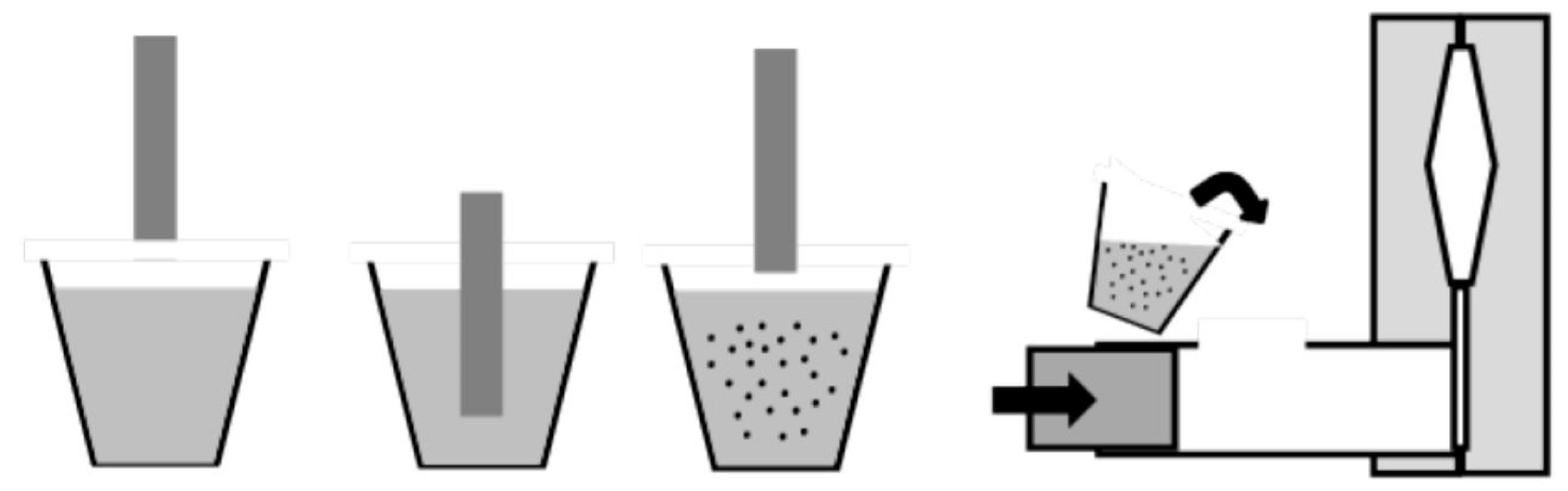
3.1. GISS Technology

The Gas Induced Super-heated Slurry process or GISS process is the market leader with more than 100 licensed units used for parts used in the automotive, heavy truck, military, electronics and medical industries [21].
The GISS process is a process that offers a cost-effective, quick installation and is an entry-level process with a low threshold for implementation of semisolid casting. The process steps in the GISS process are as follows, Figure 1 [17]:
  • The melt is ladled from the furnace with a 10 to 20 K superheat.
  • A porous graphite body is immersed for 5–20 s with Nitrogen gas seeping through this porous body. The gas bubbling results in local cooling and nucleation of the primary solid-phase to initialise the slurry formation. It should here be noted that the gas seeping out through the graphite body hinders metal from sticking to its surface to facilitate a clean retraction of the rod from the melt.
  • As the graphite body was removed, the slurry precursor is directly poured into the shot sleeve where the slurry forms and is immediately cast.
  • The ladle is cleaned returns to the processing step 1.
The primary characteristics of the process are that it runs on a relatively low fraction starting at some 5% solid fraction in the ladle and following cooling in the shot sleeve typically resulting in 25% to 30% solid fraction making is a low solid fraction process [21]. The lower solid fraction and rapid cooling during filling together with a large number of nuclei generate conditions that do not give the time nor promotes the formation of dendrites. The main control her is the time for the gas bubbling that initiates the solid phase generation and thus acts as viscosity control and the gate speed through the second phase speed in the HPDC machine. The ratio gate speed/gas bubbling tome is essentially identical to the Reynolds number and thus directly related to the level of turbulence during the die filling process. It is the possibility to control this that allows for the manufacturing of parts with intricate shapes and thin-walled parts down to 0.5 mm wall thickness [22].
A wide range of materials is found in the applications ranging from conventional casting alloys such as A356 to wrought material such as AA6061 and AA7075. In terms of post-processing, both T6 and anodising are possible depending on alloy choice.
The GISS process set-up and process characteristics are such that it can be directly implemented into an existing conventional HPDC production. This provides a low implementation threshold and also good exampled with the possibility for direct comparison and identification of the benefits of semisolid casting to conventional HPDC casting. Noticeably, as claimed by all processes, is that the thermal load on the die is reduced. The first and direct benefit is an increased die-life, as thermal fatigue, and erosion dominate die life in HPDC casting. The introduction of the GISS process has resulted in a die-life extension up to a factor of 4 compared to the corresponding HPDC process [21,22]. This has resulted in that the die-life in the GISS process has exceeding 400k parts produced in a single die. The combination of reduced heat input and a reduced fill speed furthermore allows for a reduction of die lubrication/release agents with up to 40% [22]. Die spraying reduction will directly reduce spray duration and will reduce cycle time. Additionally, as the slurry is semisolid, the time for solidification in the biscuit is reduced, shortening the time to part ejection. Reduced duration for the part ejection and spray duration has reduced cycle time with as much as 20% [21,22]. To achieve this, it is essential to manage slurry generations properly to ensure that there is no infringement on From a practical standpoint this also involves planning robot actions so that there is no waiting time due to the slurry preparation [22].
In terms of internal soundness, porosity level can be significantly reduced by the introduction of the GISS process together with the optimisation of the lubrication spray cycle. The reduced porosity allows for the delivery of parts in F, T5 and T6 states. Reduced porosity also enables weldability as in HPDC the main hinder for welding is entrained gas in the die cavity during filling. It is well-known that porosity is the main reason for rejection in HPDC processing; the use of the GISS process has resulted in rejection reductions from 30% down to 5% [22].
Intrinsic advantages originating from the thin-wall capability is that parts can be redesigned for semisolid casting weight reduction may be possible improving the sustainability of the produced components with increased resource efficiency and reduced energy content. The increased internal soundness allows for a process change from gravity die casting or low-pressure die casting to semisolid casting resulting in cycle time reduction from typically 4–8 min down to 1–2 min [22].

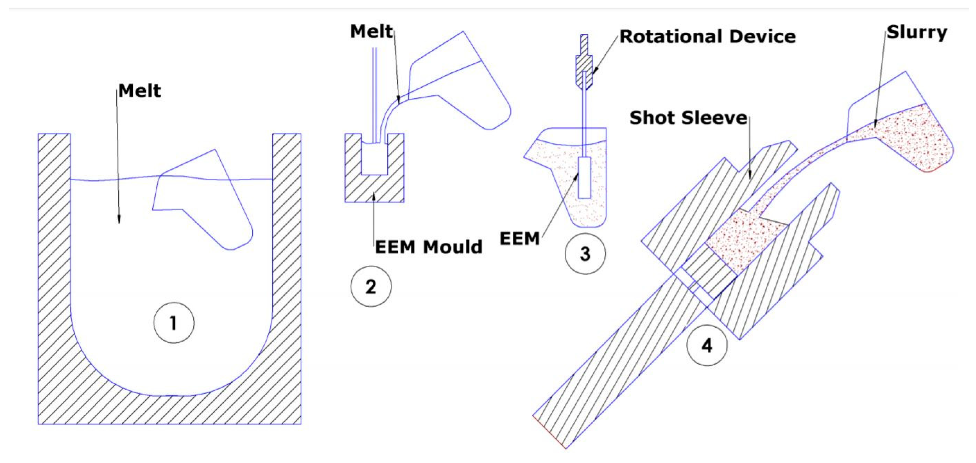
3.2. RheoMetal Process

The RheoMetal process, with more than 30 machines delivered, have primarily found applications within heat sinks and Light Emitting Diode (LED) fittings but is now finding new applications within the area of heavy trucks and automotive components [23,24]. There are also application examples from marine equipment and sports equipment as well [3]. The main characteristic is that a thick high solid fraction slurry is made in a very short time. The rapid slurry generation is enabled through the use of melting consumable or Enthalpy Exchange Material (EEM) to cool the melt into the semisolid region. The rapid slurry generation results in a highly non-equilibrium solidification in the slurry processing and a hard to predict solid fraction, but once trimmed, it is very stable and repeatable [23]. The repeatability is due to that the balance is not temperature-controlled but rather mass-based. The process steps are as follows, Figure 2:
  • A preheated ladle is filled from the furnace with a melt with a superheat of typically 20 °C, but depending on the melt delivery set up.
  • Typically, 5–8% us teemed off from the ladle and cast around a steel rod into a cylindrical shape and placed in a carousel. This material is to be used as EEM.
  • A rod with an EEM previously cast (normally six cycles earlier as the carousel typically holds six EEMs to allow degating and cooling), is immersed under rotation into the ladle with the remaining melt. The rotation provides the required shear to turn the solidified particles non-dendritic. The EEM is stirred until complete melting which typically takes 5–40 s. In newer systems, a secondary stirring is added for improved slurry homogeneity.
  • The slurry in the ladle is directly poured into the shot sleeve and injected into the mould cavity.
  • The ladle is cleaned and returned to preheating and returns to the processing step 1.
  • The steel rod is cleaned and returned to the casting station for a new EEM casting in step 2.
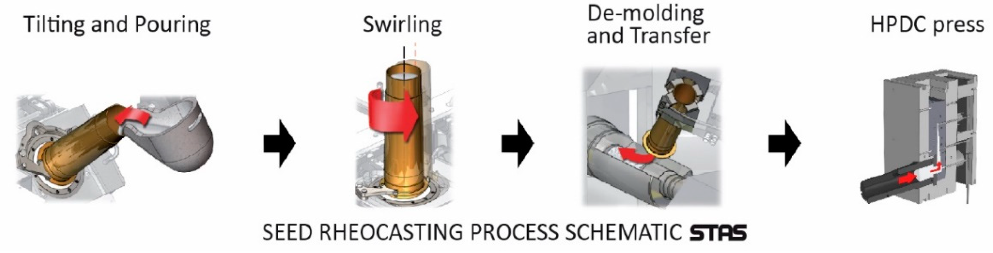
The RheoMetal process is classified as a high fraction semisolid casting process with its typically 30–45% solid phase in the slurry [26]. The normal slurry making time is within 20 s. This short duration for the shearing will create a slurry with a solid phase is less globular compared to other processes. For high strength and more demanding applications, the introduction of a short secondary stirring has improved the slurry quality to generate very low levels of porosity. The reduced porosity has also allowed for pressure-tight castings to be produced, eliminating the need for impregnation [23].
Like all semisolid processes, thin-walled components are possible, and the RheoMetal process has shown that 40 mm high walls down to 0.35 mm thicknesses can be produced industrially even for as complex products as a radio filter [23]. Compared to the other processes, fatigue loaded thick-walled components are also being produced with wall thicknesses above 10 cm being in production [3]. Again, this was achieved by strong management of the slurry quality.
The material variety for the RheoMetal process is comprehensive, and Al-8Si, A356, A357, A319, Magsimal 59 have all been realised, as well as the wrought alloy 6082. Experimentally, alloys down to 0.45% Si have been cast successfully in full industrial-scale [23,24].
Critical understanding, for the RheoMetal process, are the consequences of the deviation from equilibrium. The first issue is that as the EEM is immersed into the melt, a freeze-on layer forms [26,27,28]. This layer has a composition which is given by the composition of the solidus line in the phase diagram at the slurry forming temperature. This temperature is often just a just 2–5 °C below the liquidus of the melt. The level of solutes in the slurry particles is significantly lower than for other processes and has two direct consequences. Firstly, thermal conductivity is increased with up to 17% compared to the same material cast using HPDC or gravity die-casting. [20,29,30] The downside is that yield strength is commonly slightly lower than for HPDC casting, but ductility is improved [25,31].
In terms of die-life, the same abundance of die-life data does not exist for the RheoMetal process as it does for the GISS process due to that most of the RheoMetals products have not been HPDC cast before and direct comparison is not possible. The main reason for an increase die life is the intrinsic heat in the slurry entering the die. The higher solid fraction RheoMetal process and the associated lower amount of intrinsic heat suggest die-life should be at least that seen for the GISS process. Die-life is also depending n part size and geometry as well as on the use of lubrication agents and the air blowing cycles. Being able to reduce this also reduce the die cooling action driving the generation of tensile stress in the surface, which also may affect the die life achievable.
The use of sand cores in conjunction with the RheoMetal process has been successfully tested but not yet been fully utilised commercially [23].

3.3. SEED Process

The SEED process has shown many applications, but the market penetration is not clear. High-performance heavy-duty components for the automotive, heavy truck and sports industries have been targeted for the development of the SEED process. This type of application requires high-quality slurry. To achieve the best possible quality, the duration for the slurry making process is significantly longer for the SEED process compared to the GISS and RheoMetal processes. The longer duration of the shearing phase gives SEED an advantage in the ability to generate a good quality slurry. The higher slurry quality also enables for even higher levels of solid fraction than the GISS and RheoMetal processes. The main process steps are, Figure 3 [25]:
  • A clean slurry making container is filled from the furnace.
  • The slurry making container with the melt is placed on an oscillating table to create the swirling flow of the melt inside the container to provide the required shear in the melt to produce the globular microstructure.
  • Older systems had a draining stage to allow the high fraction solid slurry to be removed from the container. In newer systems, this step is no longer needed making the processing time shorter
  • The slurry is poured from the container into the shot sleeve, and cast using high pressure die casting equipment.
  • The ladle is cleaned and returned to preheating and returns to the processing step 1.
As part of the process design, there is a relation between the shot weight and the wall thickness of the container. The basic principle is that there should be a thermal equilibrium between the container and the slurry and to some extent the process is not purely temperature controlled but also mass controlled to provide a stable and repeatable process. The slurry making time rage from 100 s up to 160 s, hence at least three slurries need to be under processing in order to not interfere with the process as common cycle times for an HPDC casting process is in the range between 30 s and 90 s [17,25].
The high solid fraction targets high-performance parts and not ultra-thin walls components. The viscosity of a 50% solid fraction melt makes thin-walled casting, and the minimum wall thickness for SEED is 0.75 mm, thicker than what the GISS and RheoMetal process have been used to produce.
The material variety for the SEED process is similar to both RheoMetal and the GISS process but more focused towards alloys suitable for heavy-duty and high-performance application and as such not as comprehensive. SEED is, on the other hand, the only process that has targeted B206, which contains 5% Cu and is one of the highest-performing alloys that can be cast [1]. Unique to the SEED process is also that it has been used to cast Duralcan composite material and that it also has proven to improve fatigue performance with up to a 22% performance increase [25].
As for the RheoMetal process, existing data for die-life improvement is limited, but again as solid fraction is higher in the SEED process than for the other processes, and in theory, it should produce the highest die-life improvement provided that thermal fatigue is the limiting die life factor.

4. Discussion

4.1. Generic Features and Comparison to HPDC

The semisolid casting processes have recently started to expand after many years struggling to find applications significantly. The reasons for the current changes are several, but perhaps the most important change is due to that conventional HPDC processing has started to struggle to provide parts with the required features and properties. New applications for automotive components have large series, and permanent mould casting lacks sufficient productivity and cost-efficiency. The need for improved performance has driven the implementation of several new processes for high integrity castings [32,33]. It appears as the industry is at a pivoting point searching for a solution. The common traits of the processes hold a promise of a solution to many of these difficulties, Table 1.
All semisolid casting processes have in common that heat is removed from the melt and a solid phase is precipitated. The first and most noticeable effect is that viscosity is increased in the presence of the solid phase. The Reynolds number, Re, Equation (1) is a characteristic measure of the level of turbulence, and an increased viscosity will result in a reduction of Re indicating a reduced level of turbulence [34].
R e = v ρ D H μ
Here v is speed, ρ is density, DH is the hydraulic diameter/characteristic length of the system, and μ is viscosity. In semisolid casting the increase viscosity id often also combined a reduction of the injection speed, adding to the reduction of Re and turbulence. This was also the first main focus of the research as it provides the core of the process control for the injection phase, solid fraction and injection speed and also the primary contributor to the yield improvements compared to HPDC that can be seen, Table 1.
The heat removal is managed slightly differently in the processes. In the GISS process, this takes place in the ladle but perhaps foremost in the shot sleeve where the solid phase fraction increases significantly, In the RheoMetal process this occurs in the pouring ladle and the SEED process in the unique preparation crucible. Independent of this, the first consequence is that the intrinsic heat of the melt entering the mould cavity is significantly reduced and the thermal load of the mould materials is reduced. Die-life will be inherently improved. Die-life extension up to four times, compared to HPDC, is possible and that a die-life of more than 400,000 shots have been realised in production., Table 1.
The fact that the amount of heat entering the die is reduced will also reduce the die thermal distortion. The part contraction will be similar as for the HPDC processing, but the reduced thermal distortion in the die also allows for a reduced release agent usage due to a lesser amount of relative motion between the mould and casting. Release agent usage reduction as large as 40% compared to HPDC has been achieved [22]. This affects the die cavity atmosphere as the off-gassing from die-spray residues will be less than otherwise can cause significant rejection rates [35]. This reduces the available material for entrainment with or without a vacuum system during casting and reduces the requirements on venting. Similarly, reduced spraying also allows for a reduction of cycle-time with up to 20% compared to HPDC [22]. It should here be noted that the solid fraction does not strongly affect the cycle time as the solidification time in most cases is significantly shorter than the spraying cycle-time. The solid fraction is important only for systems with a large biscuit dimension. The thermal management thus affects both the par rejection rate and cycle time indirectly, Table 1.
The increased viscosity and the reduction of release agent usage together reduced tool distortion will create conditions for production with reduced rejections from porosity and fewer process interruptions as the flash formation and sticking tendencies are reduced as well. The most important part is also to realise that entrainment porosity will be located randomly and is hard to control. The pressure inside the entrained gas is also of the same order of magnitude as the die cavity pressure at the end of the intensification period. Removing these the only porosity that will remain is shrinkage porosity. Shrinkage porosity has the advantage that is can be managed through part geometry design and as such is manageable. It will also be reduced, as only 50 to 80% of the solidification takes place in the die cavity, reducing the feeding requirement. It should here be noted that due to the presence of the solid phase, feeding is more complicated and requires more research to be fully understood.
Porosity reduction will also have the most profound effect on part performance and post-processing capability. Reduction of the entrained gas will allow for heat treatment and welding as it is the entrained gas that causes the main issues for these processes with blistering and poor weldment quality.
The ability to fill combined with a high viscosity in a shear-thinning or even thixotropy allows for greater variation in section thickness than for conventional HPDC casting. This is one of the main issues for the electronics industry that is heavily depending on heatsinks with cooling fins. These fins can be made thinner with optimised distancing using semisolid casting and was also among the first industry sectors where this was used [3]. Sustainability of the casting process is thus also significantly improved, from the process-yield increase, together with the possibility of part weight reduction that together drives resource efficiency. Besides, the reduction of release agent usage also results in reduced use of silane, siloxane and resins.

4.2. Specific Capabilities

In terms of process capabilities, the different processes have different strengths making them more suitable for different applications and easy to implement. The main difference between the process resides in a specific manner the solid fraction in the slurry is generated with some very intricate differences between the processes and the resulting material characteristics and process capabilities.
The GISS process results in a slurry with a low fraction solid of the melt entering the mould cavity (5–25%). The actual treatment results in approximately 5% solid phase that acts as seeds that will aid nucleation during solidification in the shot sleeve and the die cavity. This results in relatively well-rounded particles, but the low fraction will make the cooling rates and process conditions similar to HPDC processing, compared to the other processes. This means that segregation patterns and mechanical properties will be similar to the HPDC process materials except for a significant reduction of porosity, Table 2.
The RheoMetal processing is generating a slurry rapidly with an extreme deviation from equilibrium. In contrast to both the GISS and the SEED process, the RheoMetal process has an element of Thixocasting included. The EEM that melts is not fully molten but equilibrated with the other particles in the slurry. That means that the slurry consists of particles that originate from both reheating and solidification, making the RheoMetal process a hybrid between Rheocasting and Thixocasting. Another deviation is the dendritic freeze on layer formed on the EEM, that forms and disintegrates during the slurry preparation. The primary deviation from equilibrium is chemistry-based. Due to that, the majority of the solid phase is formed at very high temperature; the primary slurry particles are lean in solutes. For an A356-type of alloy, the time to homogenise the Si and Mg content in the slurry particle s of a 70 µm diameter is approximately 30 s [28]. This is of the same order of time as it takes to make the slurry. For the RheoMetal process, it is difficult to accurately predict the amount of solid phase produced due to the kinetics of the alloy and the processing system. Under production, the shot temperatures vary less than 1 °C, even though furnace temperature is much less controlled than this. The solid fraction varies from 30–40% typically, and the flowability of the slurry limits the upper limit due to that the particles are not as round as for GISS and SEED processes. It should here be noted that the latest developments of the RheoMetal process also includes a secondary stirring step to improve slurry homogeneity and particle roundness., Table 2.
The materials proceed using the SEED process will be closer to equilibrium as the duration of the slurry making process is longer with the typical range of 100–160 s. The direct consequence of this is the generation of well-rounded particles richer in solutes. The improved shape of the particles, compared the RheoMetal process, allows the SEED process to run at higher solid fractions than the other processes (35–50%) [31].
The deviation from equilibrium seen in firstly the RheoMetal process and to a lesser degree in the GISS process with reduced amounts of dissolved solutes results in improved thermal conductivity. In the RheoMetal process, an increase by as much as 17% compared to an HPDC cast material with the same composition can be seen, Table 2.
The reduced porosity from primarily entrainment porosity allows for heat treatment. Since T6 treatments are possible, a high productivity alternative permanent mould casting is found resolving productivity issues for high-performance components. All three processes do well in the T6 condition in terms of mechanical response. In the as-cast and T5 condition, slight differences are arising from the slurry making process differences. The RheoMetal process producing a primary phase low in solutes gives a slightly lower strength but better ductility material compared to the GISS and SEED processes. Similarly, the reduced amounts of solutes will also affect the T5 response, where a slightly lower strength is to be expected in the RheoMetal process compared to GISS and SEED processes. It should be noted that this is component dependent and will be depending on the efficiency of the use of water quenching on ejection for parts that should be T5 heat treated Table 2.
Fatigue performance has for long been the weak point of castings due to porosity, and only permanent mould casting has had some success in this area. Semisolid processing is changing this. GISS that operates at lower fractions solid compared to RheoMetal and SEED will be more subjected to the existence of porosity. RheoMetal and SEED operate at a high level of solid-phase, reducing entrainment porosity effectively and will thus have a better potential och achieving excellent fatigue resistance as porosity is the leading cause of fatigue crack initiation followed by oxides. That this is the case can be seen in applications with RheoMetal being used in heavy truck components with heavy fatigue loads and SEED with an impeller with 22% improvement in fatigue life compared to HPDC, Table 2 and Table 3.
All processes are capable of casting wrought alloys for strength and also for the possibility to anodise for protection and appearance. GISS has developed colour anodised motorbike brake callipers in 7075. For the RheoMetal process, the choice of direction has been slightly different where work has focused both to cast with reduces Si amounts in the material and to increase the anodising capability to understand better the relationship between the base material and the quality of the anodised layer. Inoculation and strontium treatment together with a high fraction solid allows for better anodising outcome also for the Silicon alloyed materials, Table 2.
GISS is furthermore the only process capable of being used with permanent mould casting due to the lower solid fraction that may be generated, Table 2.

4.3. Industrial Applications

GISS has found the broadest range of application and also has the most comprehensive range of alloys tested with a proven capability. This has its foundation with the commercial success of the GISS process. The SEED process has chosen a different set of alloys with copper-rich aluminium alloys designed for strength and performance. This has been a strategic decision to focus on the automotive industry and high-value components, Table 3.
Based on the current usage of the processes GISS has an excellent cover of the automotive process with a slight dominance of passive components such as chain coves and oil pans, but also pressure-tight application such as compressor housing. The RheoMetal process also achieves pressure tightness. The SEED process, on the other hand, has more applications such as shock towers, control arms and turbo impeller with components that are subjected to high dynamic loads. This implies that for the automotive industry, the GISS and RheoMetal process have found more applications relying on thin-walled capability with weight reduction as one feature as well as reduced porosity for cost-effective impregnation free applications. The SEED process has targeted more critical high strength and high-performance components. Herein lies also the alloy capability and the use of the B206 alloy, Table 2 and Table 3.
For heavy-duty truck components, GISS relies on thin-walled and shape replication capability through gearbox castings. SEED and RheoMetal have found application in more fatigue loaded components. The RheoMetal process, in particular, has found application in thick-walled heavy-duty fatigue loaded components replacing both cast irons and forged aluminium components, Table 3.
In terms of marine components and military components, very few applications have been realised, with simple shape component realised by GISS and a slightly more complex shaped part by the RheoMetal process to relieve die sticking and production problems associated with the Magsimal59 alloy and as such use the reduced intrinsic heat in the slurry, Table 3.
Electronics components often have limited mechanical properties requirements, and the focus is more on low-cost and thermal conductivity requirements. High thermal conductivity ofter means difficult to cast alloys, and thermal transfer means complicated shape driving the capability to cast complex shapes using un-castable alloys where machining solutions are common. GISS having a short run-in and introduction cycle have found a niche in the electronics industry with a reduction of process yield improvements for the complex shape products. GISS is thus often used to improve existing production issues. A slightly different approach and the benefit were found for the RheoMetal process. The use of an EEM results in a higher slurry temperature and as a consequence making the primary phase solute lean. This particular effect results in that the RheoMetal process improves thermal conductivity, allowing an as-cast thermal conductivity that generally would require a heat treatment with other casting processes. This attractive feature also has made a niche for the RheoMetal process in electronics. The main application is, however, for new product projects. The SEED process is also capable, but due to a lesser focus on highly complex shaped electronics components and thin-walled capability, SEED has fewer applications in this area. The longer slurry making sequence would also cause a lesser deviation from equilibrium ant, thus not reap the same benefits of increase thermal conductivity as seen in the RheoMetal process, Table 3.
In the medical component area, there are only parts produces by GISS as a lightweight prosthetics focusing on internal soundness and weight without compromising part performance.
In the sports industry, bicycle components are the entry lever and motorbike components. All processes are capable, but with the high-performance target of the SEED process, there are more product examples for motorbike applications for SEED than for GISS and RheoMetal process. Here the SEED process has seen applications in the most challenging high-performance application through complex shape structural motorbike parts, Table 3.
The RheoMetal process is the only process that has found application in machinery manufacturing where the thick-walled capability is used in an application where a steel insert was over-moulded, Table 3.

5. Conclusions

The main conclusions drawn in this comparison can be made in the following areas.
  • Process differences
  • Process capabilities
  • Application areas

5.1. Process Differences

The difference between the processes resides in the actual generation of the slurry particles as this lays a foundation for the slurry characteristics. The first difference is that the GISS process generates only 5% solid phase in the ladle and the rest is a fast, dynamic process in the shot sleeve and die cavity while RheoMetal and SEED directly create more solid phase in the ladle. The consequence is that GISS generates a material more similar to HPDC processed material. This similarity also results in that the transition from HPDC to semisolid processing is relatively quick and easy. The rich nucleation and rapid cooling support the creation of relatively well-rounded particles.
RheoMetal and SEED generates a high fraction solid in the ladle/crucible, and the slurry properties are changing less dynamically in the shot sleeve and are dominated by the conditions in the ladle. The main difference is the time to process the slurry. RheoMetal typically takes 10–30 s to make the slurry while SEED takes 180 s. The primary particles in the RheoMetal are formed through kinetics, and the solid phase is far from equilibrium compared to the SEED process. This makes the RheoMetal processed slurry particles lean in solutes that alters thermal conductivity and heat treatment responses compared to what is seen in the SEED process. The longer processing time for the SEED process allows the generation of more well-rounded particles, allowing SEED to be operated at higher solid fractions than GISS and SEED.

5.2. Process Capabilities

The process capability can be seen as (1) shape capability, (2) material properties capability (3) productivity capability
Compared to HPDC, all processes have improved shape capability and especially thin-walled capability. In actual thin-walled capability, the RheoMetal process has reached furthest with 0.35 mm on a radio filter.
The materials property capability is a broad field and resides in both actual improvements in the material properties as well as in alloy capability. GISS has the broadest range of proven capability and is as such the most flexible in terms of choice. SEED has targeted high strength alloys and is as such, the choice for strength if copper is acceptable as an alloying element.
The most detrimental influence on mechanical properties ad part performance is porosity. All processes deliver materials with improved soundness compared to HPDC Defects caused by gas entrainment is reduced as the solid fraction of the slurry is increased. It should here be noted that solid fraction is not the only factor dominating the entrainment defects, but other elements such as the use of a vacuum during casting and the amount of release agent also have a strong influence on the occurrence of entrainment defects. Shrinkage porosity is part geometry dependent, but the presence of solid-phase will reduce the overall solidification shrinkage. It should also be noted that just increasing the solid fraction may not always decrease porosity as solidification characteristic and feeding resistance becomes important. Increase fraction will, however, always distribute porosity and make pores smaller supporting increased fatigue resistance explaining the benefits seen in RheoMetal and the SEED processes.
Productivity change compared to HPDC is challenging to measure, and the only bulk of data existing originates from the GISS process where direct comparisons were made. Both cycle-time and process yield improvements were realised. It is not clear if these can be realised to the same amounts for the RheoMetal and SEED processes. This requires a reduction of the release agent usage. Increasing the solid fraction means, however, that the heat received into the die is reduced and that should reduce distortion and allow for a reduced release agent usage. In theory, this is possible but convincing proof of actual achievement is missing. Die life data has a similar relationship to the amount of solid fraction with an increasing fraction reducing the thermal load and as such, should improve die-life. GISS has actual achievements recorded that can be compared. Again, in theory, this is also possible for RheoMetal process and SEED process, but the actual convincing proof is still missing.

5.3. Application Areas

GISS has so far found the widest applications which likely is due to its ease of introduction. This is also the likely reason for that there exist more direct comparisons between HPDC and GISS. RheoMetal and SEED appear to be introduced to new projects where HPDC is unable to support the requirements on the component.
GISS has been applied in almost all areas in terms of applications, but the dominant field is within the electronics industry. This suggests that the main benefits of the GISS process reside in productivity improvements and the capability to produce complex-shaped sound products effectively. The immediate proven gains are found in rejection rates, cycle times, release agent usage and foremost also in die-life improvements. The electronics industry also benefits from that the primary phase is somewhat lean in solutes and can provide improved thermal conductivity of the material compared to HPDC.
The RheoMetal process has two main areas where it is applied, electronics and in the heavy truck component manufacturing. The electronics applications are found in China where it is the complex-shape capability together with the significantly improved thermal conductivity, due to the reduced amounts of dissolved solutes in the solid phase, that drives the application. The European heavy truck industry uses the reduced porosity to make heavy sectioned components competing with cast iron and forged aluminium component that are under fatigue load. These are in heat-treated conditions and often a T5 condition. This has taken some development effort in process control and timing. The T5 response in the RheoMetal process is more difficult compared to the other processes due to the reduced amount of solutes in the slurry phase and is entirely dominated by the Mg content in the slurry particles [31].
The SEED process is capable of producing heatsinks just as GISS and RheoMetal, but due to the relatively high solid fraction used the extremely thin-wall capability has not been achieved. The longer processing timed does not support the significant improvements in thermal conductivity seen in the GISS and RheoMetal process. The focus has been to draw benefit from the high solid fraction and to use this to cast high-performance alloys and to drive its implementation toward extremely demanding parts. These parts are often complex shape, relatively thin-walled and will often require T6 heat treatment. The achievable mechanical properties are higher than what is seen for GISS and RheoMetal using alloys such as B207.

Funding

This research was funded by the Knowledge Foundation, grant number 20170066.

Acknowledgments

The author is deeply indebted to Jessada Wannasin with GISSCO, Pascal Cote with STAS and to Magnus Wessén, with the RheoMetal company as well as Per Jansson and Staffan Zetterström with Comptech and last but not least Chen Qiurong with the RheoComp Technology company, previously Fujian RheoMet Light Metals, for providing information on applications and capabilities of their processes to make this work possible. The acknowledgement also includes providing the illustrations used in the current paper.

Conflicts of Interest

The author declares no conflict of interest.

References

  1. Midson, S.P. Semisolid Metal Casting. In ASM Handbook Aluminum Science and Technology; ASM: Almere, The Netherlands, 2018; Volume 2A, pp. 400–408. [Google Scholar]
  2. Decker, R.F. The Technology and Commercialization of Thixomolding®. Solid State Phenom. 2012, 192–193, 47. [Google Scholar] [CrossRef]
  3. Jarfors, A.E.W.; Zheng, J.C.; Chen, L.; Yang, J. Recent Advances in Commercial Application of the Rheometal Process in China and Europe. Solid State Phenom. 2019, 285, 405–410. [Google Scholar] [CrossRef]
  4. Pan, Q.Y.; Apelian, D.; Alexandrou, A.N. Yield behavior of commercial Al-Si alloys in the semisolid state. Metall. Mater. Trans. B 2004, 35, 1187–1202. [Google Scholar] [CrossRef]
  5. Chen, J.; Xue, L.; Wang, S.H. Experimental studies on process-induced morphological characteristics of macro- and microstructures in laser consolidated alloys. J. Mater. Sci. 2011, 46, 5859–5875. [Google Scholar] [CrossRef] [Green Version]
  6. Espinosa, I.; Menargues, S.; Baile, M.T.; Picas, J.A.; Forn, A. SLC components as an alternative to extruded alloys for marine applications. Int. J. Mater. Form. 2008, 1 (Suppl. 1), 993–996. [Google Scholar] [CrossRef]
  7. Menargues, S.; Martín, E.; Baile, M.T.; Picas, J.A. New short T6 heat treatments for aluminium silicon alloys obtained by semisolid forming. Mater. Sci. Eng. A 2015, 621, 236–242. [Google Scholar] [CrossRef]
  8. Yurko, J.A.; Martinez, R.A.; Flemings, M.C. Development of the semisolid rheocasting (SSR) process 2002. In Proceedings of the The 7th International Conference on Semi-Solid Processing of Alloys and Composites, Tsukuba, Japan, 25–27 September 2002; pp. 659–664. [Google Scholar]
  9. Reisi, M.; Niroumand, B. Growth of primary particles during secondary cooling of a rheocast alloy. J. Alloys Compd. 2009, 475, 643–647. [Google Scholar] [CrossRef]
  10. Campillo, M.; Baile, M.T.; Menargues, S.; Forn, A. The effect of injection conditions on the structural integrity of the components produced by semisolid Rheocasting. Int. J. Mater. Form. 2010, 3, 751–754. [Google Scholar] [CrossRef] [Green Version]
  11. Canyook, R.; Petsut, S.; Wisutmethangoon, S.; Flemings, M.C.; Wannasin, J. Evolution of microstructure in semisolid slurries of rheocast aluminum alloy. Trans. Nonferrous Met. Soc. China (Engl. Ed.) 2010, 20, 1649–1655. [Google Scholar] [CrossRef]
  12. Li, D.Q.; Zhang, F.; Midson, S.P.; Liang, X.K.; Yao, H. Recent developments of rheo-diecast components for transportation markets. Solid State Phenom. 2019, 285, 417–422. [Google Scholar] [CrossRef]
  13. Nafisi, S.; Lashkari, O.; Ghomashchi, R.; Ajersch, F.; Charette, A. Microstructure and rheological behavior of grain refined and modified semisolid A356 Al-Si slurries. Acta Mater. 2006, 54, 3503–3511. [Google Scholar] [CrossRef]
  14. STAS SEED Swireled Enthalpy Equilibration Device An Innovative Process for the Production of High Integrity Die Casting Parts How It Works. Available online: https://www.stas.com/wp-content/uploads/2018/08/seed_2018v02.pdf (accessed on 12 October 2020).
  15. Langlais, J.; Lemieux, A. The SEED technology for semisolid processing of aluminum alloys: A metallurgical and process overview. Solid State Phenom. 2006, 116–117, 472–477. [Google Scholar] [CrossRef]
  16. Côté, P.; Bryksi, V.; Stunova, B.B. Case study: Engine bracket made by rheocasting using the seed process. Solid State Phenom. 2019, 285, 441–445. [Google Scholar] [CrossRef]
  17. Doutre, D.; Hay, G.; Wales, P.; Gabathuler, J.P. SEED: A new process for semisolid forming. Can. Metall. Q. 2004, 43, 265–272. [Google Scholar] [CrossRef]
  18. Luo, M.; Li, D.; Midson, S.P.; Qu, W.; Zhu, Q.; Fan, J. Model for Predicting Radial Temperature Distribution of Semi-Solid Slug Produced by Swirled Enthalpy Equilibration Device (SEED) Process. J. Mater. Process. Technol. 2019, 273, 116236. [Google Scholar] [CrossRef]
  19. Santos, J.; Jarfors, A.E.W.; Dahle, A.K. Filling, Feeding and Defect Formation of Thick-Walled AlSi7Mg0.3 Semi-Solid Castings. Solid State Phenom. 2016, 256, 222–227. [Google Scholar] [CrossRef] [Green Version]
  20. Payandeh, M.; Sjölander, E.; Jarfors, A.E.W.E.W.; Wessén, M. Influence of microstructure and heat treatment on thermal conductivity of rheocast and liquid die cast Al-6Si-2Cu-Zn alloy. Int. J. Cast Met. Res. 2016, 29, 202–213. [Google Scholar] [CrossRef] [Green Version]
  21. Wannasin, J.; (GISSCO, Songkhla, Thailand). Private communication, 2019.
  22. Wannasin, J.; Fuchs, M.; Lee, J.; Lee, C.U.; Narasimha Rao, T.V.L.; Flemings, M.C. Giss technology: Principle and applications in die casting. Solid State Phenom. 2019, 285, 470–475. [Google Scholar] [CrossRef]
  23. Wessén, M.; RheoMetal AB, Stocholm, Sweden. Private Communication, 2019.
  24. Chen, Q.; (Fujian RheoMet Light Metals, Sanming, Jiangle County, China). Private communication, 2019.
  25. Cote, P.; (STAS, Chicoutimi, Canada). Private communication, 2019.
  26. Payandeh, M.; Jarfors, A.E.W.W.; Wessén, M. Solidification Sequence and Evolution of Microstructure During Rheocasting of Four Al-Si-Mg-Fe Alloys with Low Si Content. Metall. Mater. Trans. A Phys. Metall. Mater. Sci. 2016, 47, 1215–1228. [Google Scholar] [CrossRef]
  27. Payandeh, M.; Jarfors, A.E.W.A.E.W.; Wessén, M. Effect of Superheat on Melting Rate of EEM of Al Alloys during Stirring Using the RheoMetal Process. Solid State Phenom. 2012, 192–193, 392–397. [Google Scholar] [CrossRef] [Green Version]
  28. Payandeh, M.; Sabzevar, M.H.; Jarfors, A.E.W.; Wessén, M. Solidification and Re-melting Phenomena During Slurry Preparation Using the RheoMetalTM Process. Metall. Mater. Trans. B Process Metall. Mater. Process. Sci. 2017, 48, 2836–2848. [Google Scholar] [CrossRef] [Green Version]
  29. Payandeh, M.; Sjölander, E.; Jarfors, A.E.W.; Wessen, M. Mechanical and thermal properties of rheocast telecom component using low silicon aluminium alloy in as-cast and heat-treated conditions. In TMS Light Metals; Springer: Cham, Switzerland, 2015; Volume 2015-Janua. [Google Scholar]
  30. Bjurenstedt, A.; Fredriksson, M.; Bogdanoff, T.; Jarfors, A.E.W. Optimised Heat Treatment for High Pressure Die Cast Aluminium Components (OPTIHEAT); Swerea SWECAST: Jönköping, Sweden, 2018. [Google Scholar]
  31. Santos, J.; Dahle, A.K.; Jarfors, A.E.W. Magnesium solubility in primary α-al and heat treatment response of cast Al-7Si-Mg. Metals 2020, 10, 614. [Google Scholar] [CrossRef]
  32. Jorstad, J.; Apelian, D. Pressure assisted processes for high integrity aluminum castings. Int. J. Met. 2008, 2, 41. [Google Scholar] [CrossRef]
  33. Jorstad, J. Pressure assisted processes for high integrity aluminium castings-part 2. Foundry Trade J. 2009, 183, 282–287. [Google Scholar]
  34. Bird, R.B.; Stewart, W.E.; Lightfoot, E.N. Transport Phenomena, 2nd ed.; John Wiley & Sons, Inc.: New York, NY, USA, 2002; ISBN 0-471-41077-2. [Google Scholar]
  35. Jarfors, A.E.W.; Tong, S.; Hu, B.; Sharma, N.; Wee, C. Mechanism of Lubrication-Induced Surface Cracking in Hot Chamber Die Cast Thin-Walled AZ91D Parts. Mater. Manuf. Process. 2003, 18, 637–641. [Google Scholar] [CrossRef]
Figure 1. The Gas-Induced Superheated-Slurry (GISS) process (courtesy GISSCO).
Metals 10 01368 g001
Figure 2. The RheoMetal process (courtesy Comptech).
Metals 10 01368 g002
Figure 3. The Swirling Enthalpy Equilibration Device (SEED) process (Courtesy STAS).
Metals 10 01368 g003
Table 1. Collation of common traits [21,22,23,24,25].
Common ElementComment
Tool lifeReduced thermal load on dies improve die-life with GISS and SEED proving up to 4 times that of HPDC
Lubrication/release agent usedGISS has proven reductions of 40%
Cycle time reductionGISS has proven cycle time reductions of 20% compared to an HPDC cycle
Process yieldsGISS shows from 30% to 5% and RheoMetal from scrap rates of 20% to well below 1%.
ProductivityMany applications mean a change from gravity die casting or low-pressure die casting to rheocasting with cycle time changes from 4–8 min to 1–2 min in Rheocasting as it is based on the HPDC cycle. Productivity is also increased due to yield increase
Weight reductionThe thin-walled capability allows for significant weight reduction (Radio filter down to 72% of HPDC cast version)
WeldabilityPorosity reduction gives increased weldability
Heat treatmentAll processes have proven that F, T5 and T6 conditions are possible
Table 2. Collation of process capabilities [21,22,23,24,25].
Capability MeasureGISSRheoMetalSEED
Anodizing and surface treatmentColour anodising possibleThick anodising layers possibleAnodizing possible.
Anodizing of 7xxx, 6xxx alloys and Al-Mg alloy
Fatigue resistanceN/AExcellent with thick-walled componentExcellent.
Ex. Up to 22% increase in fatigue life (turbo impeller case)
Wall thicknessFrom >10 cm down to less than 0.5 mm, most common 1–3 mmFrom >10 cm down to less than 0.35 mm, most common 2–3 mmDown to 0.75 mm
Proven alloy capabilityCasting alloys: A356, Al-Si7, A380, A383, Silafont 36, Magsimal 59, A390,
Pure Aluminum
Casting alloys: Al-8Si, A356, A357, A319, Magsimal 59Casting alloys: A356, A357, 319S, B206
Wrought alloys: 6063, 6061, 5082, 7075Wrought alloys: 6082Wrought alloys: 6061
StrengthNormal strengthSofter as-cast condition Excellent elongationNormal strength
Moderate T5 responseModerate T5 responseExcellent Elongation
Excellent T6 responseExcellent T6 ResponseExcellent T6 response
Other notable achievementsColour anodising to thin-walled and thick-walled componentsExperimental casting tested successfully down to 0.45% SiHigh-Solid fraction up to 50%
Used in gravity die casting with a cycle time reduction of up to 20%Pressure tight castings without impregnationProcess range from 2 kg to 18 kg slugs.
Pressure tight castings
without impregnation
Use of sand coresOther alloys:
Improved thermal conductivity by up to 15%Improved thermal conductivity by up to 17%Duralcan composite
Flexibility to switch between rheocasting and HPDC-Suitable for 20–40 kg slurries
Excellent slurry homogeneity due to secondary stirring
Flexibility to switch between rheocasting and HPDC
Table 3. Collation of components in production [21,22,23,24,25].
Application AreaGISSRheoMetalSEED
AutomotiveAuto gearboxCompressor partsBrackets
Brake system componentsCooling units for power electronicsControl arm
Chain coversEngine bearing cap
Engine blockEngine bracket
Oil panShock towers
Steering wheelsTurbo impeller
ElectronicsHandphone coversHeat sinksHeat sinks
Hard disc drive housingRadio filters 4G and 5G
Heat sinks
Radio filters 4G and 5G
Heavy Duty Truck
components
Truck gearboxCAB mountsBattery holder
Muffler holders Brake calliper
Brackets
Knuckle
Skeleton joint
MachineryMachine parts with steel inserts
Marine applicationSacrificial anodeWinch housing
Medical componentsProsthetics
Military componentsCast 7075 composite armour plate
SportsBicycle componentsBicycle componentsMotocross frame structural components (steering knuckle and others)
Motorcycle partsWheel knuckle (Quad)

