Investigations on Tailored Forming of AISI 52100 as Rolling Bearing Raceway

 ,
,  ,
,  , , , ,
  and
and
Abstract

1. Introduction
2. State-of-the-Art
3. Aim and Research Objectives
- Which welding parameters are necessary to functionalize bearing steel that is normally declared as not weldable?
- How do the downstream processes need to be adjusted in order to achieve a high component quality for use as rolling bearings raceways?
- What is the microstructure of the material compound after the different manufacturing steps?
- Were the relevant component properties for use as a rolling bearing component achieved?
- What are the relevant mechanisms that govern the fatigue behavior?
- What damage patterns occur when used as a rolling bearing raceway?
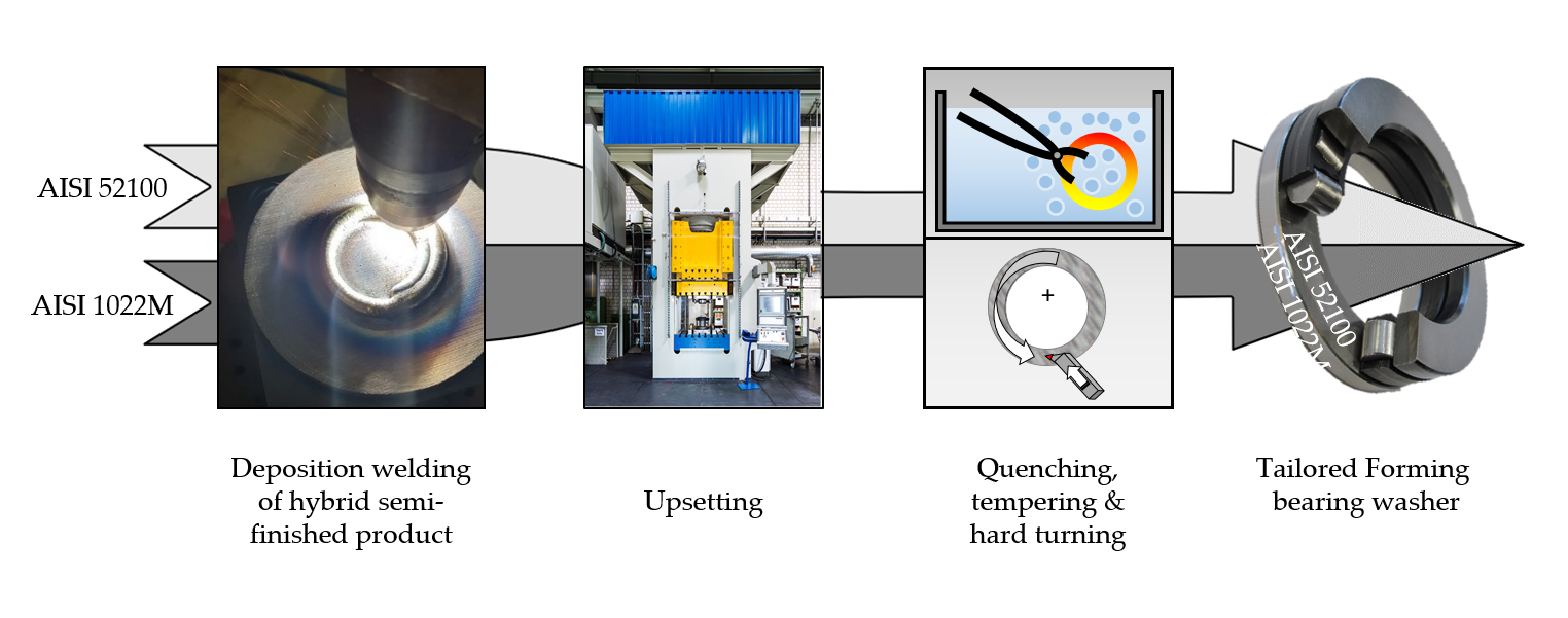
4. Materials and Methods
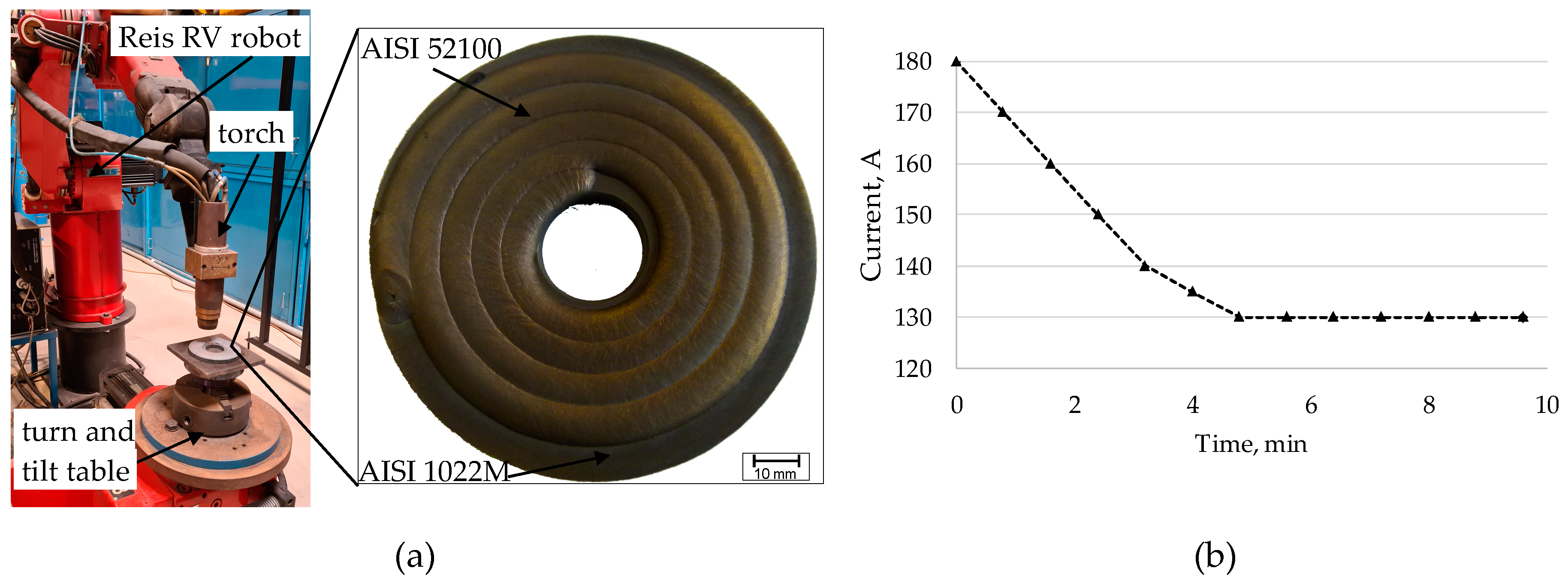
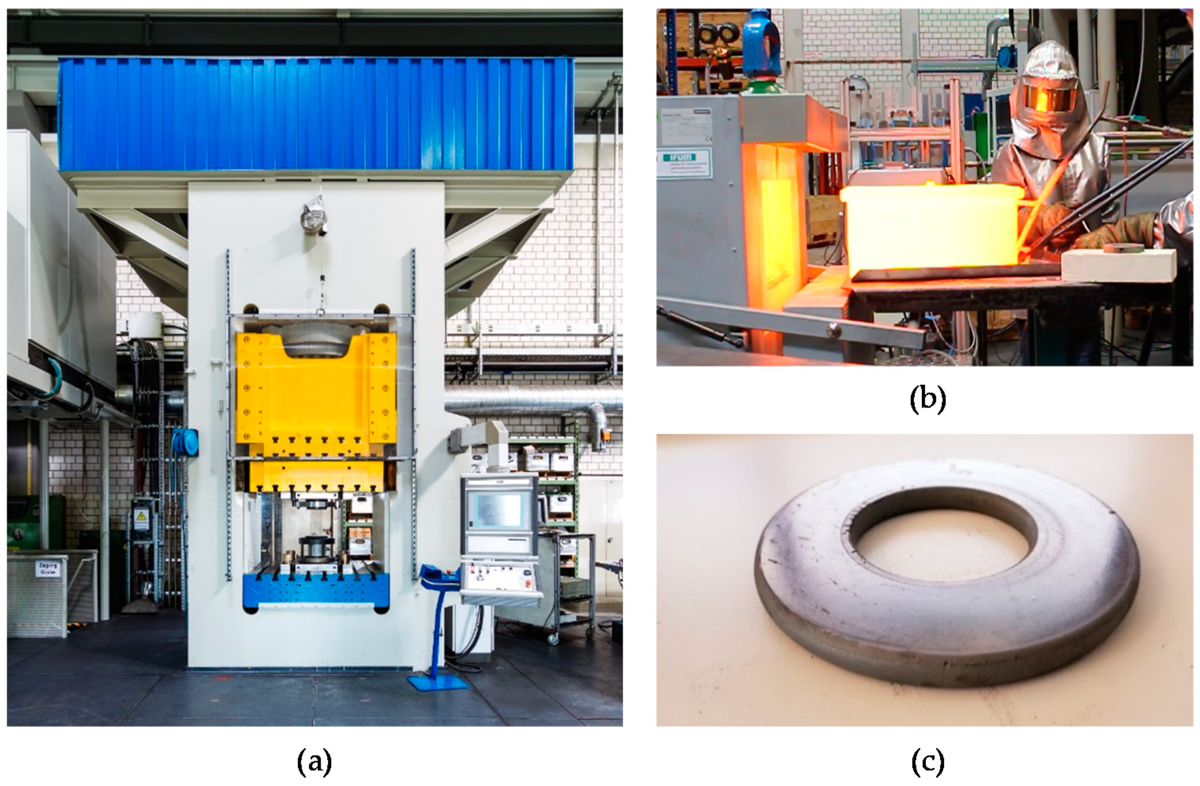
4.1. Plasma Transferred Arc Deposition Welding
4.2. Upsetting
4.3. Heat Treatment
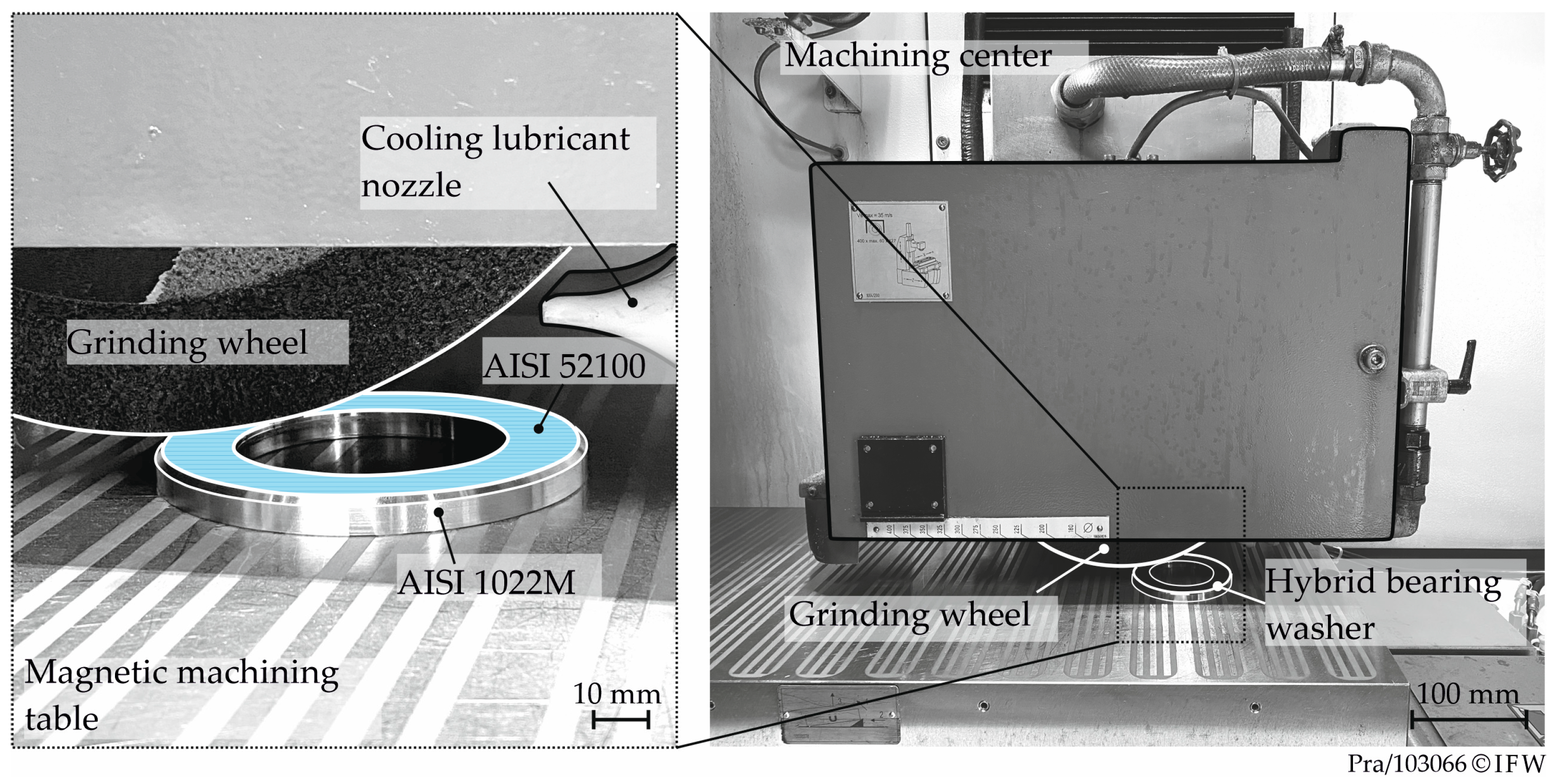
4.4. Machining
4.5. Analytical Methods
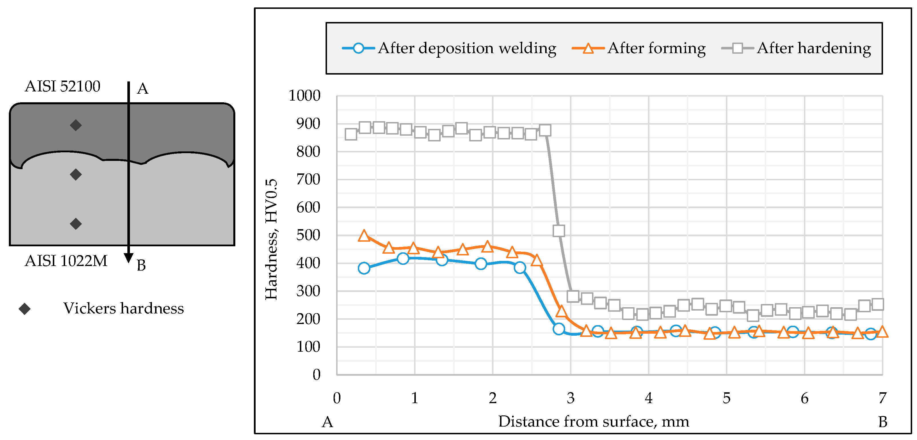
4.5.1. Metallographic Investigations and Hardness Measurements
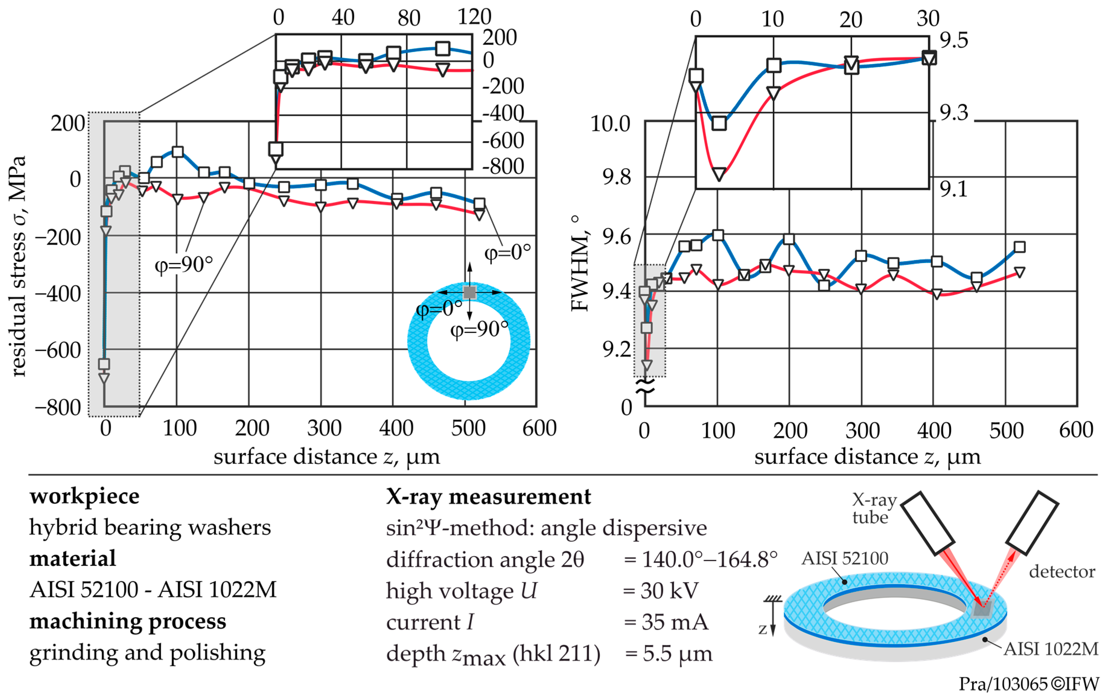
4.5.2. Residual Stress Measurements
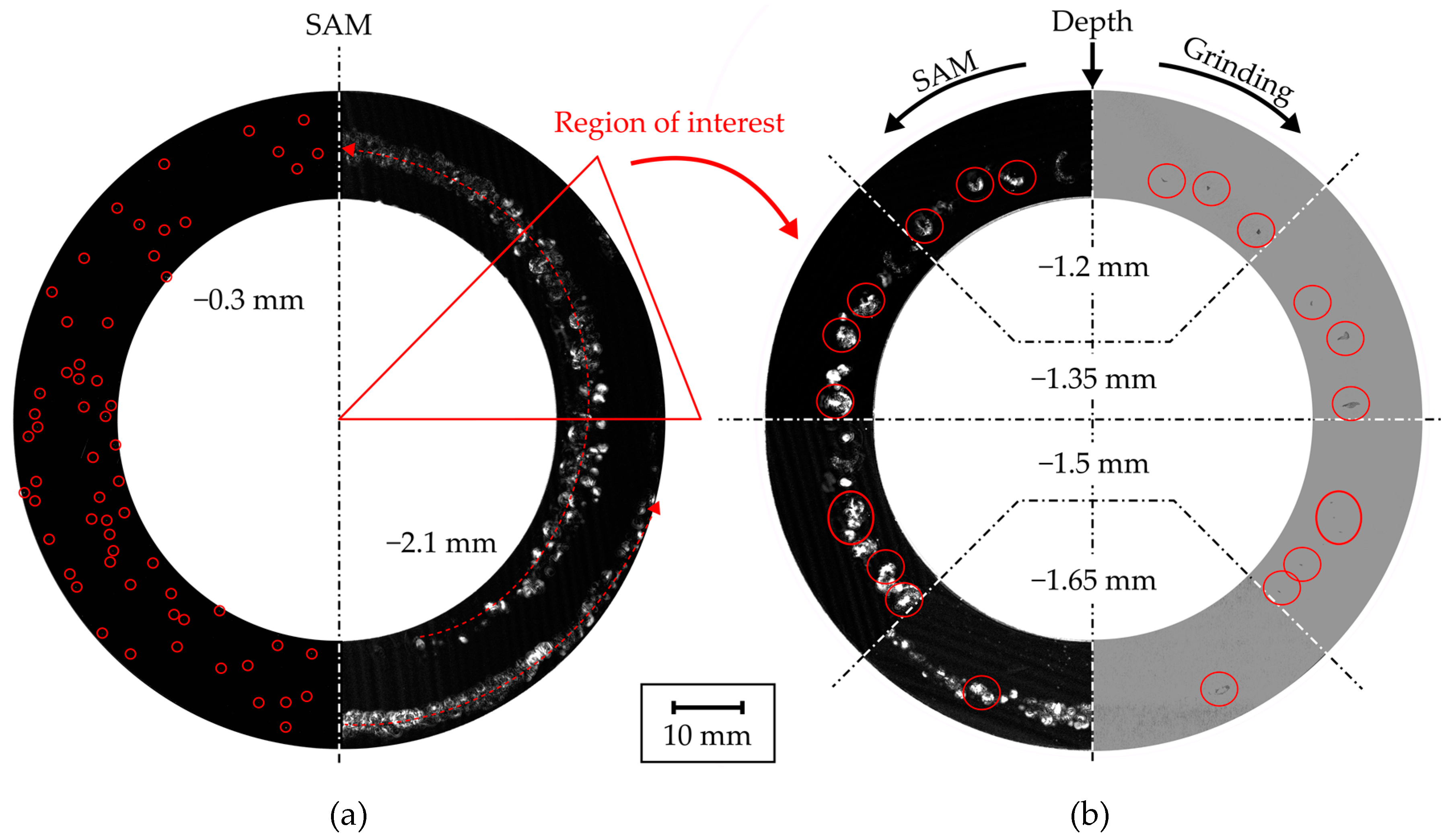
4.5.3. Non-Destructive Examination
4.5.4. Bearing Fatigue Testing
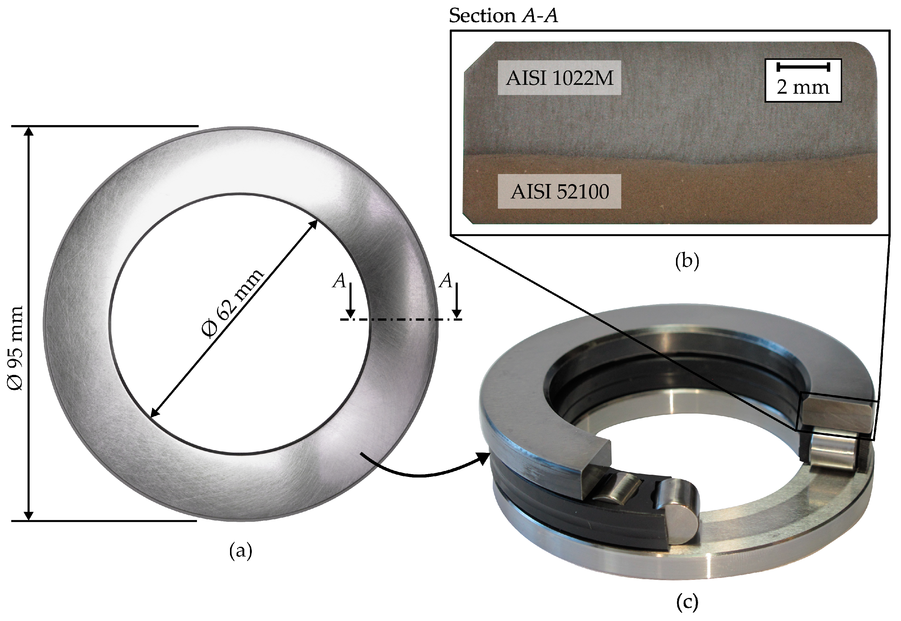
5. Results and Discussion
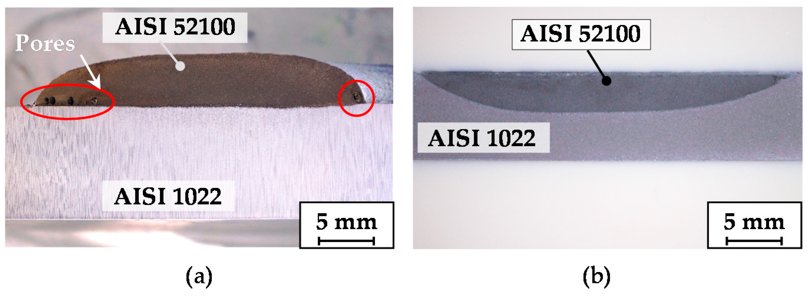
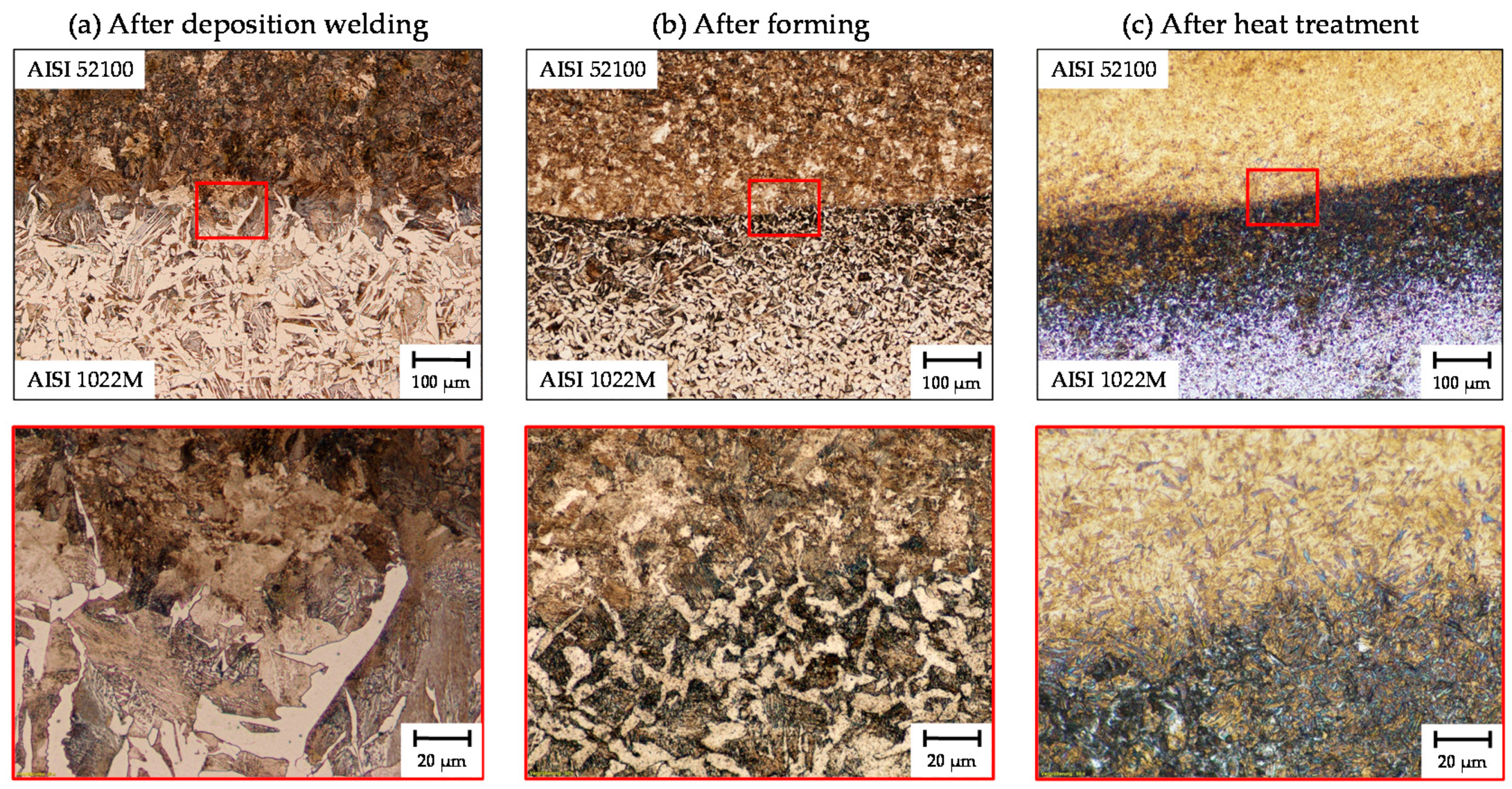
5.1. Microstructure Evolution during Processing
5.2. Residual Stress State
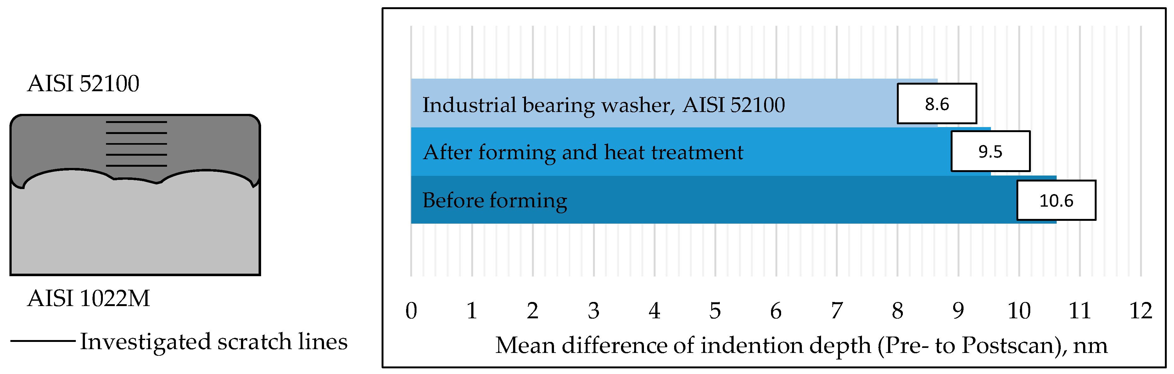
5.3. Microtribological Investigations
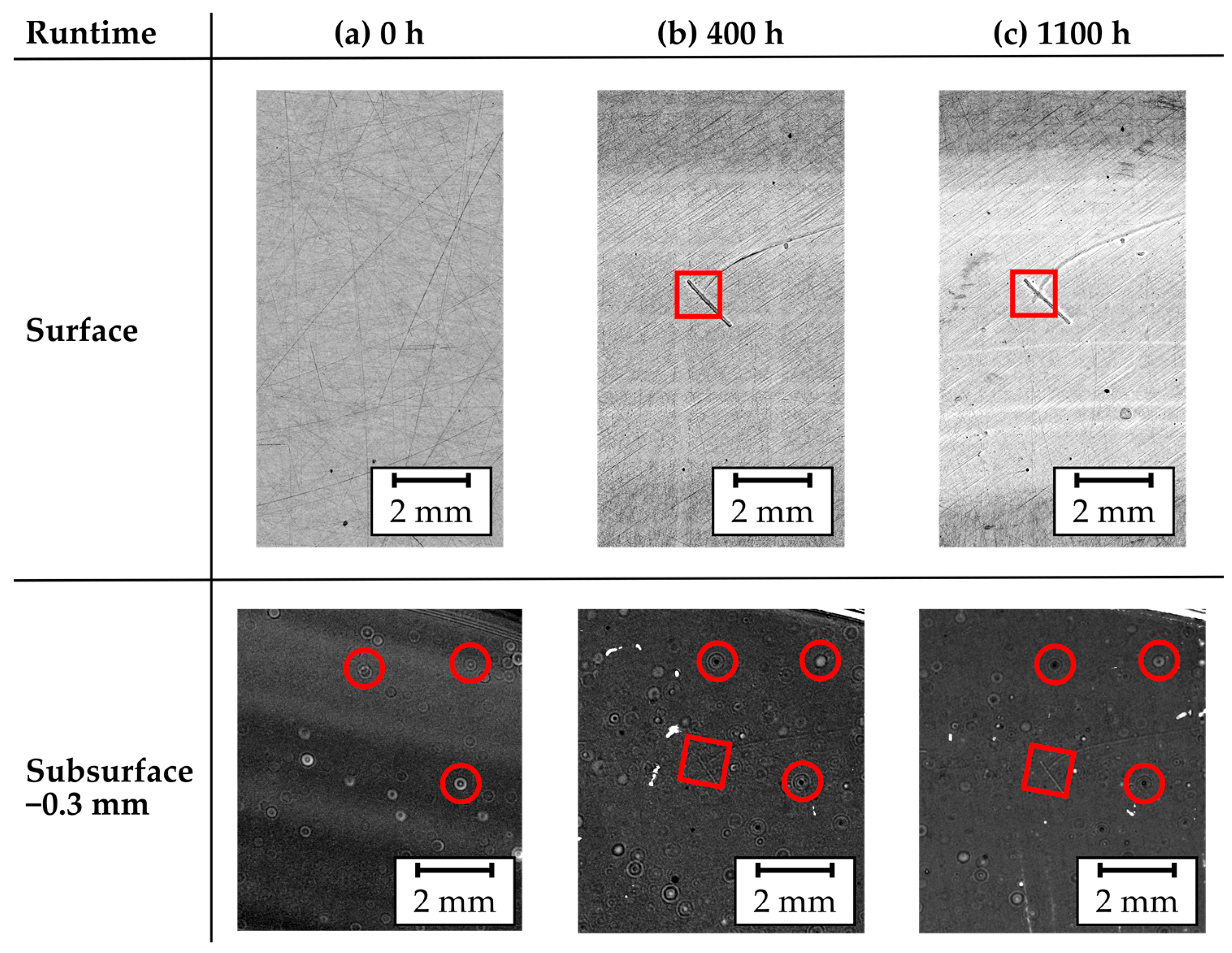
5.4. Optical and Acoustic Microscopy
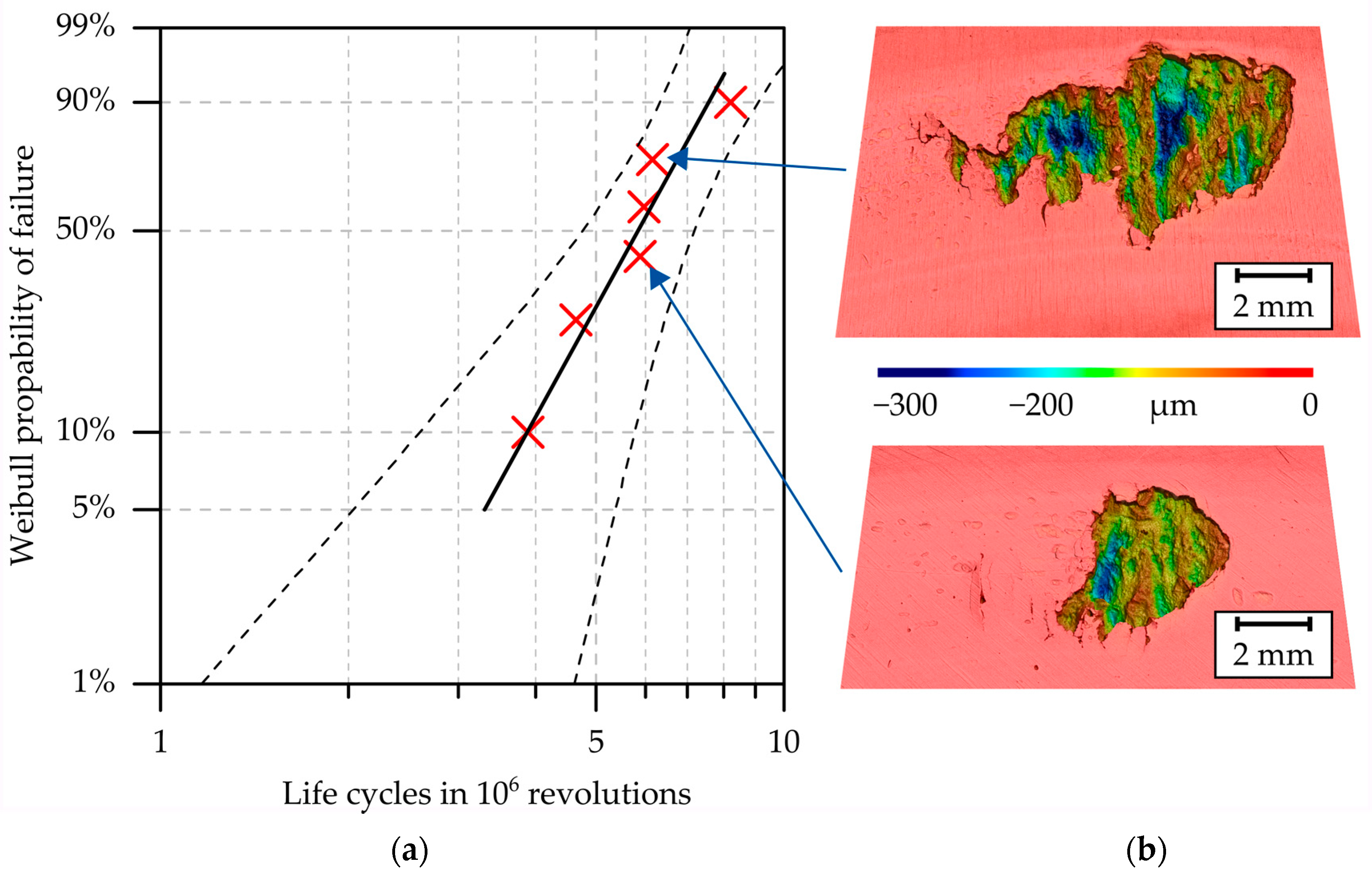
5.5. Rolling Contact Fatigue Performance
5.5.1. Screening Test
5.5.2. Pitting Tests
- Run-in procedure for 24 h at a reduced speed of 500 min−1,
- Fatigue test for the remaining 176 h at 750 min−1.
6. Conclusions
- AISI 52100 is considered as non-weldable, but it was possible to weld by means of PTA. The challenge of reducing pores during the welding process in order to increase the bearing fatigue life still remains.
- The forming process demonstrated a positive impact on the microstructure in the interface zone. Besides a grain refinement in the clad material, the Widmanstätten structure was fully recrystallized. Moreover, the porosity occurring after PTA was significantly reduced and a defect-free material transition between the base material and the cladding material was observed.
- Hardness values similar to those of industrial bearings were achieved by the applied heat treatment of quenching and tempering.
- Residual stress measurements demonstrated that no critical tensile residual stresses occurred at the surface of the hybrid bearing washers like in industrial bearing washers. High compressive residual stresses on the subsurface avoided premature failure of the bearing washers.
- By using AISI 52100 as cladding material, the load-bearing capacity of the tailored forming bearing washers was increased compared to AISI 5140 and AISI HNV3 claddings. Eighty-two percent of the calculated modified rating life for conventional bearings L10m was achieved. The slope of the determined Weibull curve indicates premature damage. By means of SAM, pores and cavities could be detected, which were probably responsible for this.
Author Contributions
Funding
Acknowledgments
Conflicts of Interest
References
- Blohm, T.; Mildebrath, M.; Stonis, M.; Langner, J.; Hassel, T.; Behrens, B.-A. Investigation of the cladding thickness of plasma-transferred arc deposition welded and cross wedge rolled hybrid parts. Prod. Eng. 2017, 11, 255–263. [Google Scholar] [CrossRef]
- Mildebrath, M.; Blohm, T.; Hassel, T.; Stonis, M.; Langner, J.; Maier, H.J.; Behrens, B.-A. Influence of Cross Wedge Rolling on the Cladding Quality of Plasma-Transferred Arc Deposition Welded Hybrid Steel Parts. Int. J. Emerg. Technol. Adv. Eng. 2017, 7, 1–7. [Google Scholar]
- Cento, P.; Dareing, D.W. Ceramic Materials in Hybrid Ball Bearings. Tribol. Trans. 1999, 42, 707–714. [Google Scholar] [CrossRef]
- Wan, G.T.Y.; Gabelli, A.; Ioannides, E. Increased Performance of Hybrid Bearings with Silicon Nitride Balls. Tribol. Trans. 1997, 40, 701–707. [Google Scholar] [CrossRef]
- Dill, J.F. Hybrid bearing technology for advanced turbomachinery. J. Eng. Gas Turbines Power 1996, 118, 173–178. [Google Scholar] [CrossRef]
- Koehler, H.; Schumacher, J.; Schuischel, K.; Partes, K.; Bomas, H.; Jablonski, F.; Vollertsen, F.; Kienzler, R. An approach to calculate fatigue properties of laser cladded components. Prod. Eng. 2012, 6, 137–148. [Google Scholar] [CrossRef]
- Koehler, H.; Partes, K.; Seefeld, T.; Vollertsen, F. Influence of laser reconditioning on fatigue properties of crankshafts. Phys. Procedia 2011, 12, 512–518. [Google Scholar] [CrossRef]
- Alam, M.M.; Kaplan, A.; Tuominen, J.; Vuoristo, P.; Miettinen, J.; Poutala, J.; Näkki, J.; Junkala, J.; Peltola, T.; Barsoum, Z. Analysis of the stress raising action of flaws in laser clad deposits. Mater. Des. 2013, 46, 328–337. [Google Scholar] [CrossRef]
- Chew, Y.; Hock Lye Pang, J.; Bi, G.; Song, B. Effects of laser cladding on fatigue performance of AISI 4340 steel in the as-clad and machine treated conditions. J. Mater. 2017, 243, 246–257. [Google Scholar] [CrossRef]
- Pape, F.; Coors, T.; Poll, G. Studies on the Influence of Residual Stresses on the Fatigue Life of Rolling Bearings in Dependence on the Production Processes. Front. Mech. Eng. 2020, 6. [Google Scholar] [CrossRef]
- Mildebrath, M.; Coors, T.; Barroi, A.; Pape, F.; Lammers, M.; Hermsdorf, J.; Overmeyer, L.; Poll, G.; Hassel, T. Herstellungsprozess und Wälzfestigkeit von hybriden Hochleistungsbauteilen. Konstruktion 2018, 9, 84–89. [Google Scholar]
- Behrens, B.-A.; Amiri, A.; Duran, D.; Nothdurft, S.; Hermsdorf, J.; Kaierle, S.; Ohrdes, H.; Wallaschek, J.; Hassel, T. Improving the mechanical properties of laser beam welded hybrid workpieces by deformation processing. AIP Conf. Proc. 2019, 2113. [Google Scholar] [CrossRef]
- Pape, F.; Coors, T.; Barroi, A.; Hermsdorf, J.; Mildebrath, M.; Hassel, T.; Kaierle, S.; Matthias, T.; Chugreev, A.; Chugreeva, A.; et al. Tribological Study on Tailored-Formed Axial Bearing Washers. Tribol. Online 2018, 12. [Google Scholar] [CrossRef]
- Behrens, B.-A.; Chugreev, A.; Matthias, T.; Poll, G.; Pape, F.; Coors, T.; Hassel, T.; Maier, H.J.; Mildebrath, M. Manufacturing and Evaluation of Multi-Material Axial-Bearing Washers by Tailored forming. Metals 2019, 9, 232. [Google Scholar] [CrossRef]
- Stanford, M.K.; Jain, V.K. Friction and wear characteristics of hard cladding. Wear 2001, 251, 990–996. [Google Scholar] [CrossRef]
- Matthes, K.; Schneider, W. Schweißtechnik–Schweißen von metallischen Konstruktionswerkstoffen, 6th ed.; Hanser Verlag: München, Germany, 2016; pp. 33–34. [Google Scholar]
- Schneider, W.; Twrdek, J. Praxiswissen Schweißtechnik, 6th ed.; Springer: Wiesbaden, Germany, 2019; p. 268. [Google Scholar]
- Dilthey, U. Schweißtechnische Fertigungsverfahren 2—Verhalten der Werkstoffe beim Schweißen, 3rd ed.; Springer: Berlin, Germany, 2005; p. 130. [Google Scholar]
- Kittner, K.; Wiesner, J.; Kawalla, R. A new approach for void closure in bulk metal forming. Key Eng. Mater. 2016, 716, 595–604. [Google Scholar] [CrossRef]
- DIN EN ISO 6507, Metallic Materials—Vickers Hardness Test; International Organization for Standardization: Geneva, Switzerland, 2005.
- DIN EN ISO 6508, Metallic Materials—Rockwell Hardness Test; International Organization for Standardization: Geneva, Switzerland, 2005.
- Krektuleva, R.V.; Cherepanov, O.I.; Cherepanov, R.O. Numerical investigation of residual thermal stresses in welded joints of heterogeneous steels with account of technological features of multi-pass welding. Appl. Math. Model. 2016, 42, 244–256. [Google Scholar] [CrossRef]
- Kanakaraju, V.; Gunjal, S.; Rathinam, K.; Sharma, P. Optimization of cutting parameters of residual stresses in simultaneous turning technique. Mater. Today Proc. 2020, 28, 2108–2115. [Google Scholar] [CrossRef]
- Jawahir, I.S.; Brinksmeier, E.; M’Saoubi, R.; Aspinwall, D.K.; Outeiro, J.C.; Meyer, D.; Umbrello, D.; Jayal, A.D. Surface integrity in material removal processes: Recent advances. CIRP Ann. 2011, 60, 603–626. [Google Scholar] [CrossRef]
- Breidenstein, B. Oberflächen und Randzonen hoch Belasteter Bauteile. Habilitation Thesis, Leibniz University Hannover, Hannover, Germany, 2011. [Google Scholar]
- Novovic, D.; Dewes, R.C.; Aspinwall, D.K.; Voice, W.; Bowen, P. The effect of machined topography and integrity on fatigue life. Int. J. Mach. Tools Manuf. 2004, 44, 125–134. [Google Scholar] [CrossRef]
- Guo, J.; Fu, H.; Pan, B.; Kang, R. Recent progress of residual stress measurement methods: A review. Chin. J. Aeronaut. 2020. [CrossRef]
- Macherauch, E.; Müller, P. Das sin2psi-Verfahren der röntgenographischen Spannungsmessung. Z. Angew. Phys. 1961, 13, 305–312. [Google Scholar]
- Eigenmann, B.; Macherauch, E. Röntgenographische Untersuchung von Spannungszuständen in Werkstoffen, Teil III. Mater. Werkst. 1996, 27, 426–437. [Google Scholar] [CrossRef]
- DIN 51819, Testing of Lubricants—Mechanical-Dynamic Testing in the Roller Bearing Test Apparatus FE8—Part 1: General working principles; Deutsches Institut für Normung e.V.: Berlin, Germany, 2016.
- ISO 16889, Hydraulic Fluid Power—Filters—Multi-Pass Method for Evaluating Filtration Performance of a Filter Element; International Organization for Standardization: Geneva, Switzerland, 2008.
- Jamshidi, H.; Budak, E. Grinding Temperature Modeling Based on a Time Dependent Heat Source. Procedia CIRP 2018, 77, 299–302. [Google Scholar] [CrossRef]
- Zhao, Z.; Qian, N.; Ding, W.; Wang, Y.; Fu, Y. Profile grinding of DZ125 nickel-based superalloy: Grinding heat, temperature field, and surface quality. J. Manuf. Process. 2020, 57, 10–22. [Google Scholar] [CrossRef]
- Rabiey, M.; Maerchy, P. Investigation on Surface Integrity of Steel DIN 100Cr6 by Grinding Using CBN Tool. Procedia CIRP CSI 2020, 87, 192–197. [Google Scholar] [CrossRef]
- VW PV 1483, Factory Standard, Gear Oils—Testing the Pitting Load Capacity in Rolling Bearings (in German); Volkswagen AG: Wolfsburg, Germany, 2007.
- DIN ISO 281, Rolling Bearings—Dynamic Load Ratings and Rating Life; International Organization for Standardization: Geneva, Switzerland, 2007.
- Ioannides, E.; Bergling, G.; Gabelli, A. An Analytical Formulation for the Life of Rolling Bearings. In Acta Polytechnica Scandinavica; Mechanical Engineering Series 137; Finnish Academies of Technology: Espoo, Finland, 1999. [Google Scholar]


| AISI | C | Si | Mn | P | S | Cr |
|---|---|---|---|---|---|---|
| 1022 M | 0.22 | 0.29 | 0.84 | 0.01 | 0.001 | 0.04 |
| 52100 | 0.97 | 0.25 | 0.31 | 0.01 | 0.004 | 1.38 |
| Parameter | Value | Parameter | Value |
|---|---|---|---|
| Shielding gas flow (argon) | 10 L/min | Current | 180–130 A |
| Plasma gas flow (argon) | 1.5 L/min | Voltage | 25–27 V |
| Transport gas flow (argon) | 6 L/min | Powder material | AISI 52100 |
| Welding velocity | 0.12 m/min | Particle size | 0.06–0.2 mm |
| Working distance | 10 mm | Deposition rate | 0.9 kg/h |
| Parameter | Value |
|---|---|
| Forming temperature | 1050 °C |
| Furnace shielding gas | argon |
| Forging force | 1700 kN |
| Height reduction | 35% |
| Final height | 9 mm |
| Parameter | Value | Parameter | Value | ||
|---|---|---|---|---|---|
| Speed | n | 500–750 min−1 | Axial load | Fax | 60 kN |
| Viscosity at 40 °C | ν40 | 68 mm2/s | Load equivalent | C/P | 2.87 |
| Oil temperature | TOil | 95 °C | Contact load | F1 | 3.16 kN |
| Viscosity ratio | 𝜅 | 0.44 | Contact pressure | pmax | 1.8 GPa |
| Variable | Value | |
|---|---|---|
| Weibull shape parameter | β | 3.47 |
| Experimental life | B10 | 3.88 × 10⁶ revs. |
| Adjusted speed | nref | 300 min−1 |
| Life exponent | p | 10/3 |
| Life factor | aISO | 0.14 |
| Modified rating life | L10m | 4.75 × 10⁶ revs. |
| Deviation factor | B10/L10m | 0.82 |
© 2020 by the authors. Licensee MDPI, Basel, Switzerland. This article is an open access article distributed under the terms and conditions of the Creative Commons Attribution (CC BY) license (http://creativecommons.org/licenses/by/4.0/).
Share and Cite
Coors, T.; Mildebrath, M.; Büdenbender, C.; Saure, F.; Faqiri, M.Y.; Kahra, C.; Prasanthan, V.; Chugreeva, A.; Matthias, T.; Budde, L.; et al. Investigations on Tailored Forming of AISI 52100 as Rolling Bearing Raceway. Metals 2020, 10, 1363. https://doi.org/10.3390/met10101363
Coors T, Mildebrath M, Büdenbender C, Saure F, Faqiri MY, Kahra C, Prasanthan V, Chugreeva A, Matthias T, Budde L, et al. Investigations on Tailored Forming of AISI 52100 as Rolling Bearing Raceway. Metals. 2020; 10(10):1363. https://doi.org/10.3390/met10101363
Chicago/Turabian StyleCoors, Timm, Maximilian Mildebrath, Christoph Büdenbender, Felix Saure, Mohamad Yusuf Faqiri, Christoph Kahra, Vannila Prasanthan, Anna Chugreeva, Tim Matthias, Laura Budde, and et al. 2020. "Investigations on Tailored Forming of AISI 52100 as Rolling Bearing Raceway" Metals 10, no. 10: 1363. https://doi.org/10.3390/met10101363
APA StyleCoors, T., Mildebrath, M., Büdenbender, C., Saure, F., Faqiri, M. Y., Kahra, C., Prasanthan, V., Chugreeva, A., Matthias, T., Budde, L., Pape, F., Nürnberger, F., Hassel, T., Hermsdorf, J., Overmeyer, L., Breidenstein, B., Denkena, B., Behrens, B.-A., Maier, H. J., & Poll, G. (2020). Investigations on Tailored Forming of AISI 52100 as Rolling Bearing Raceway. Metals, 10(10), 1363. https://doi.org/10.3390/met10101363