The Impact of EMS on the Temperature Fluctuations, Appearance, and Microstructure of GTA Stainless Steel Welds


Abstract
1. Introduction
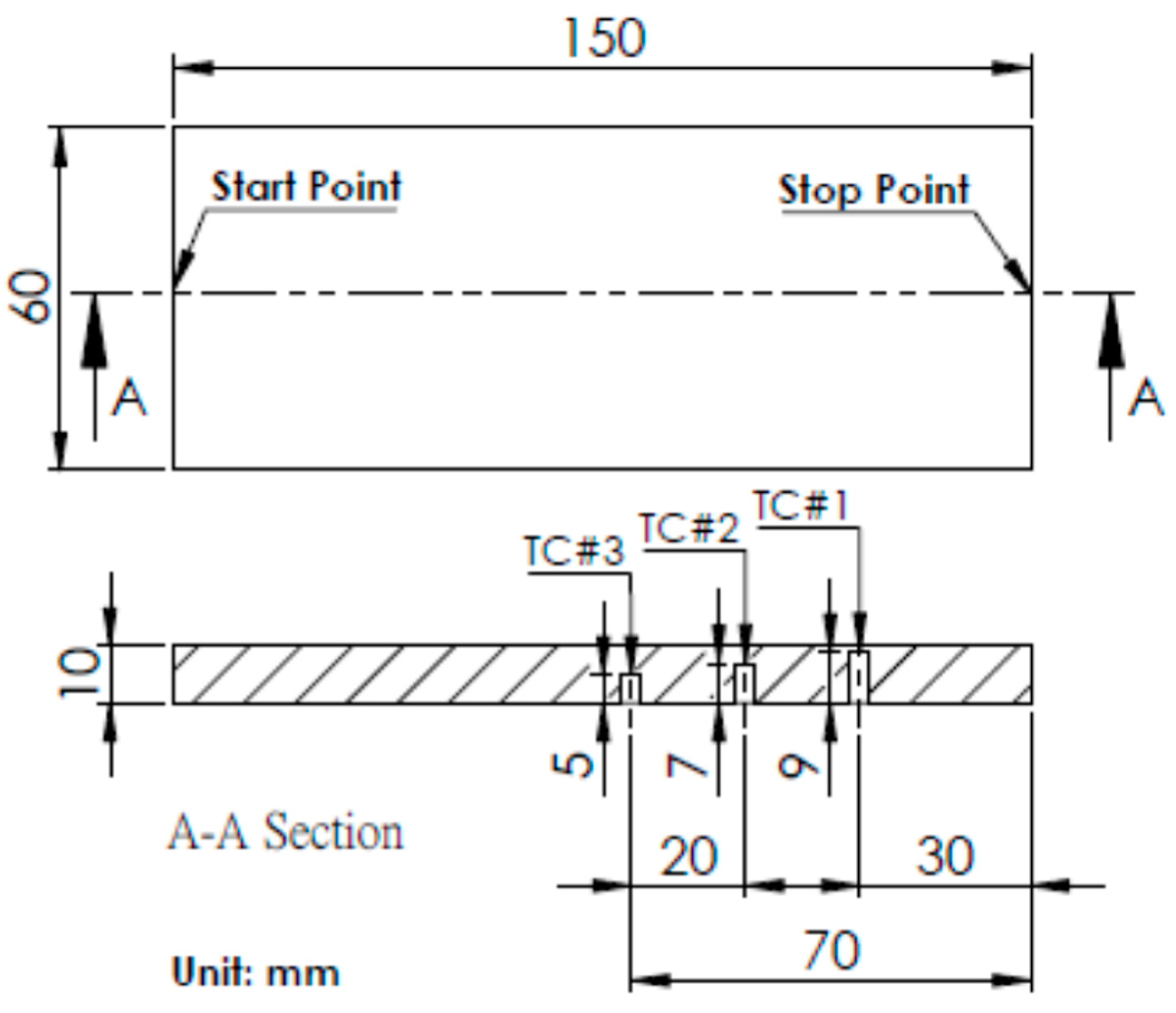
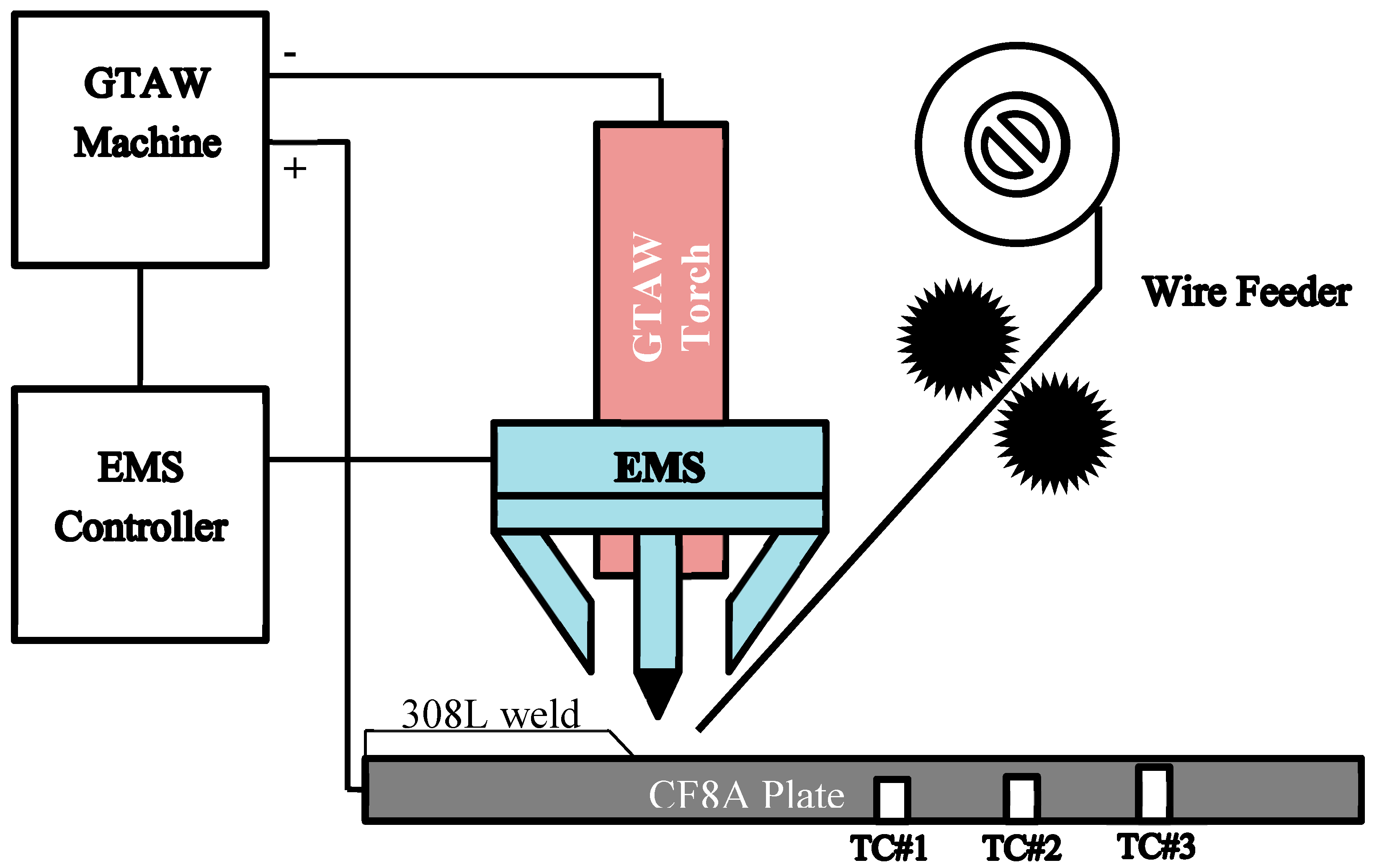
2. Materials and Methods
3. Results
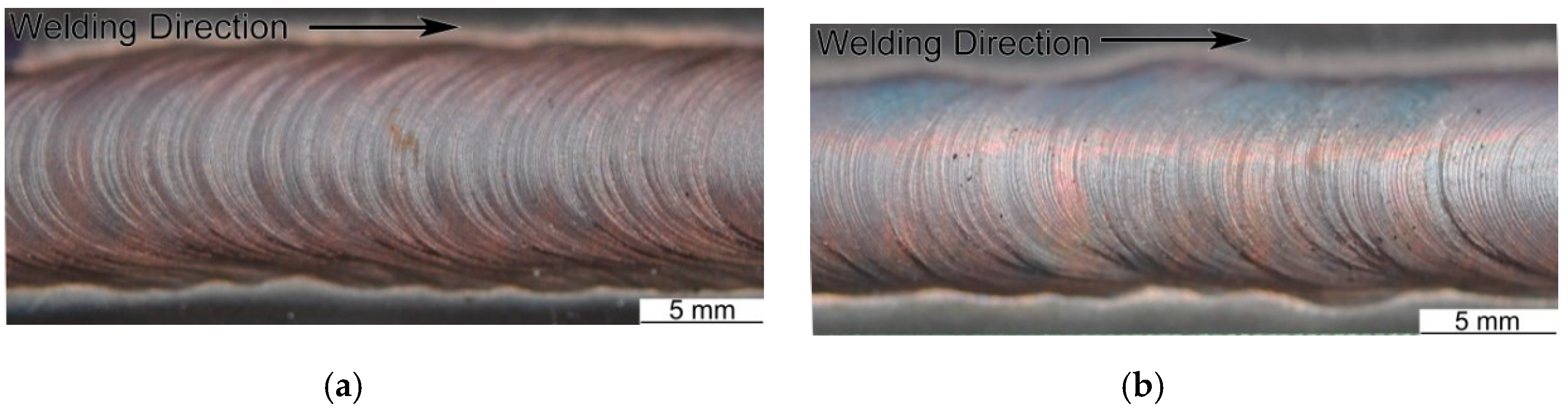
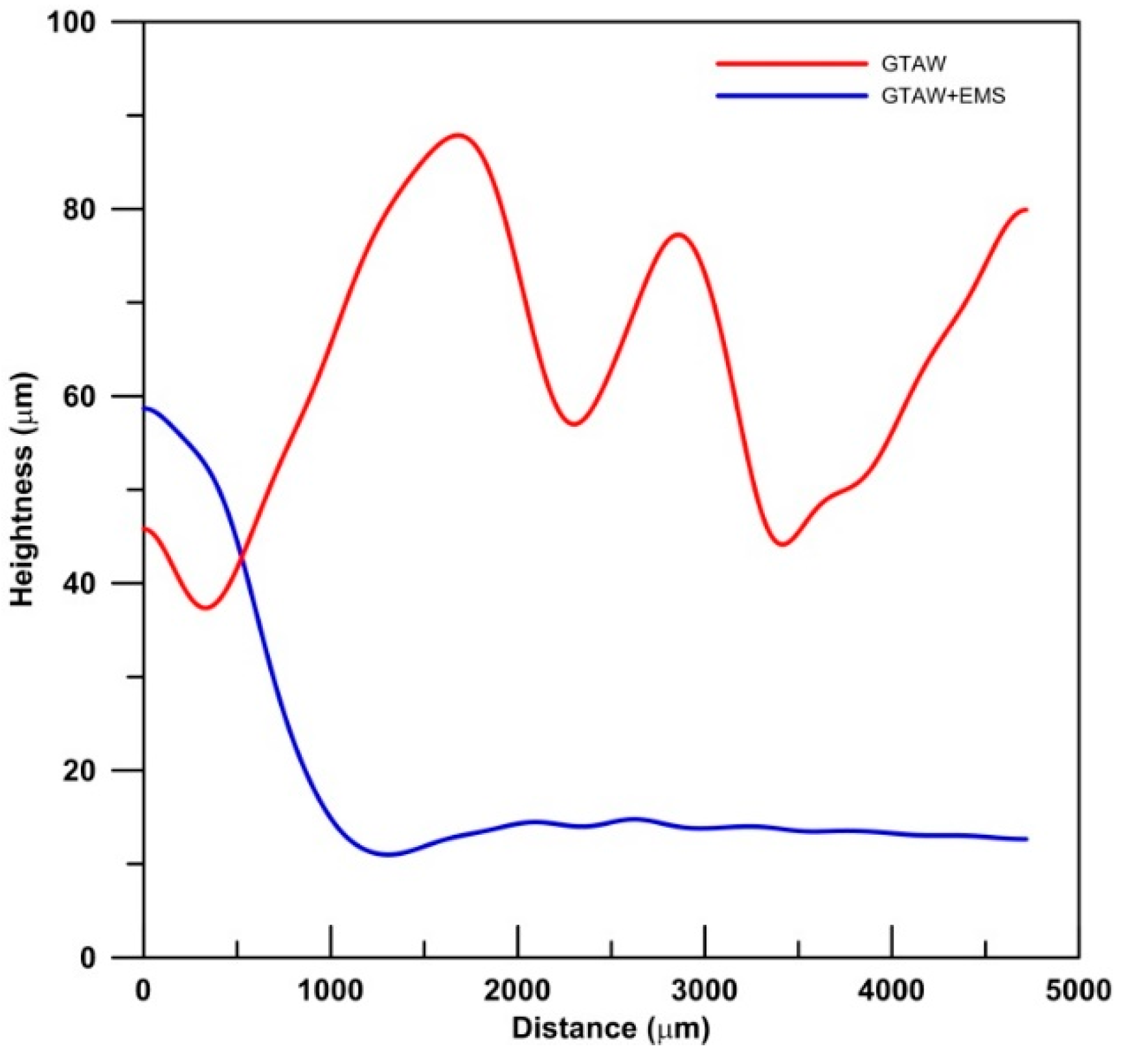
3.1. Weld Surface
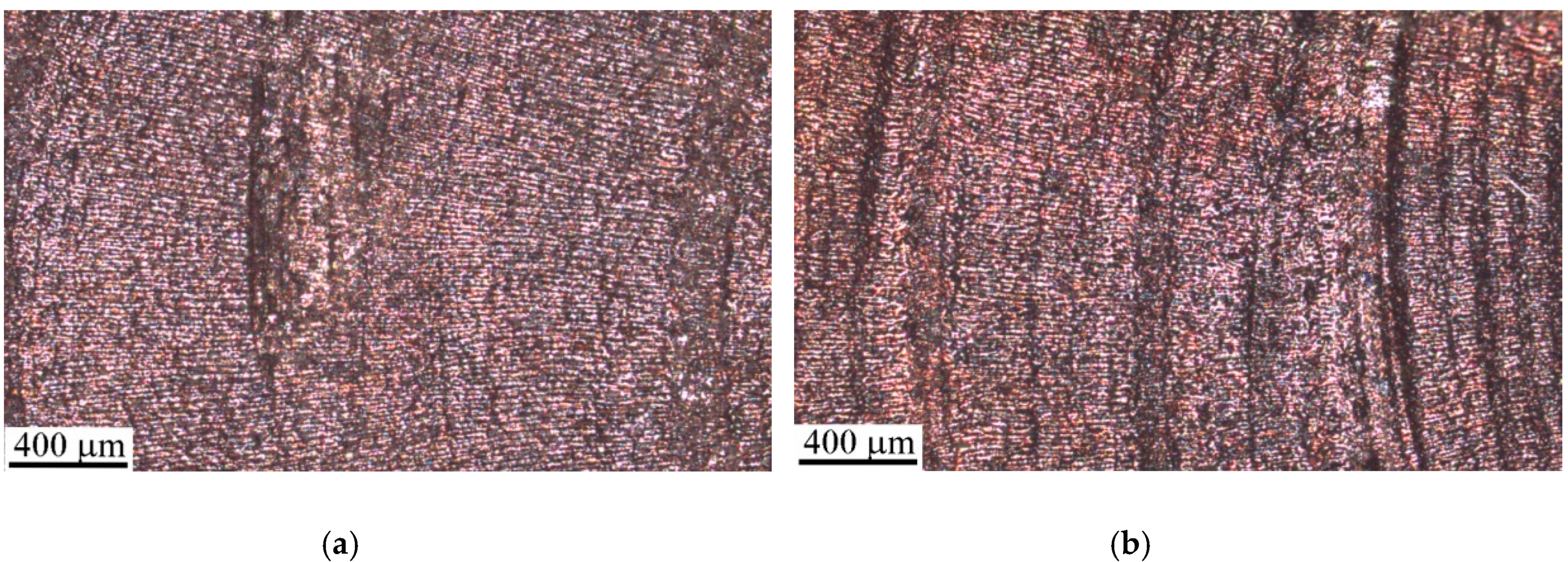
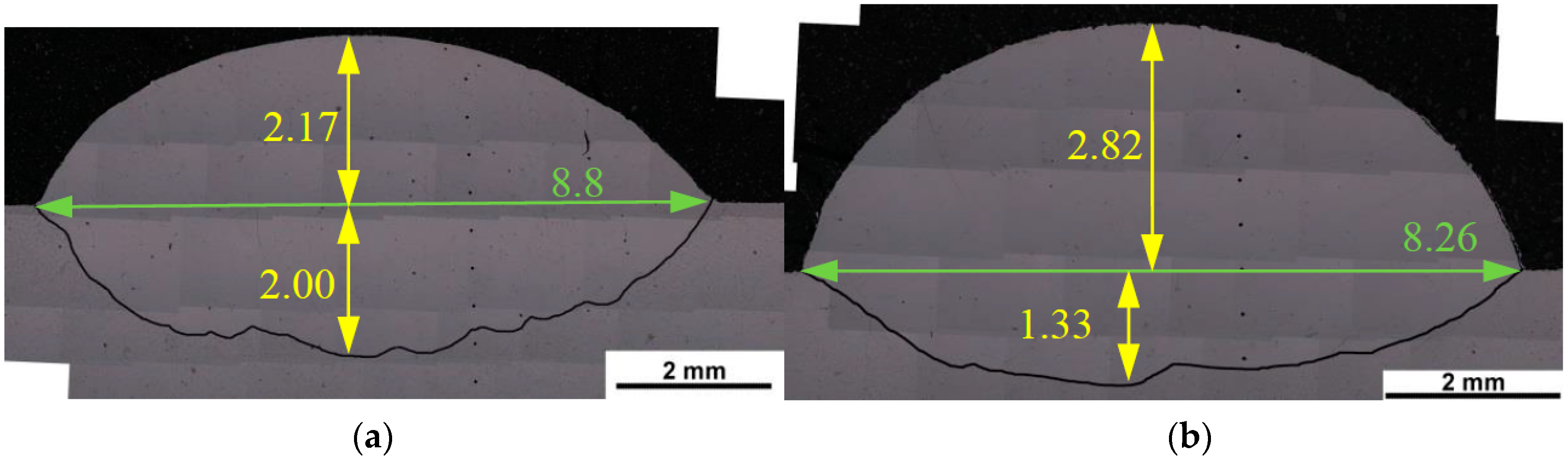
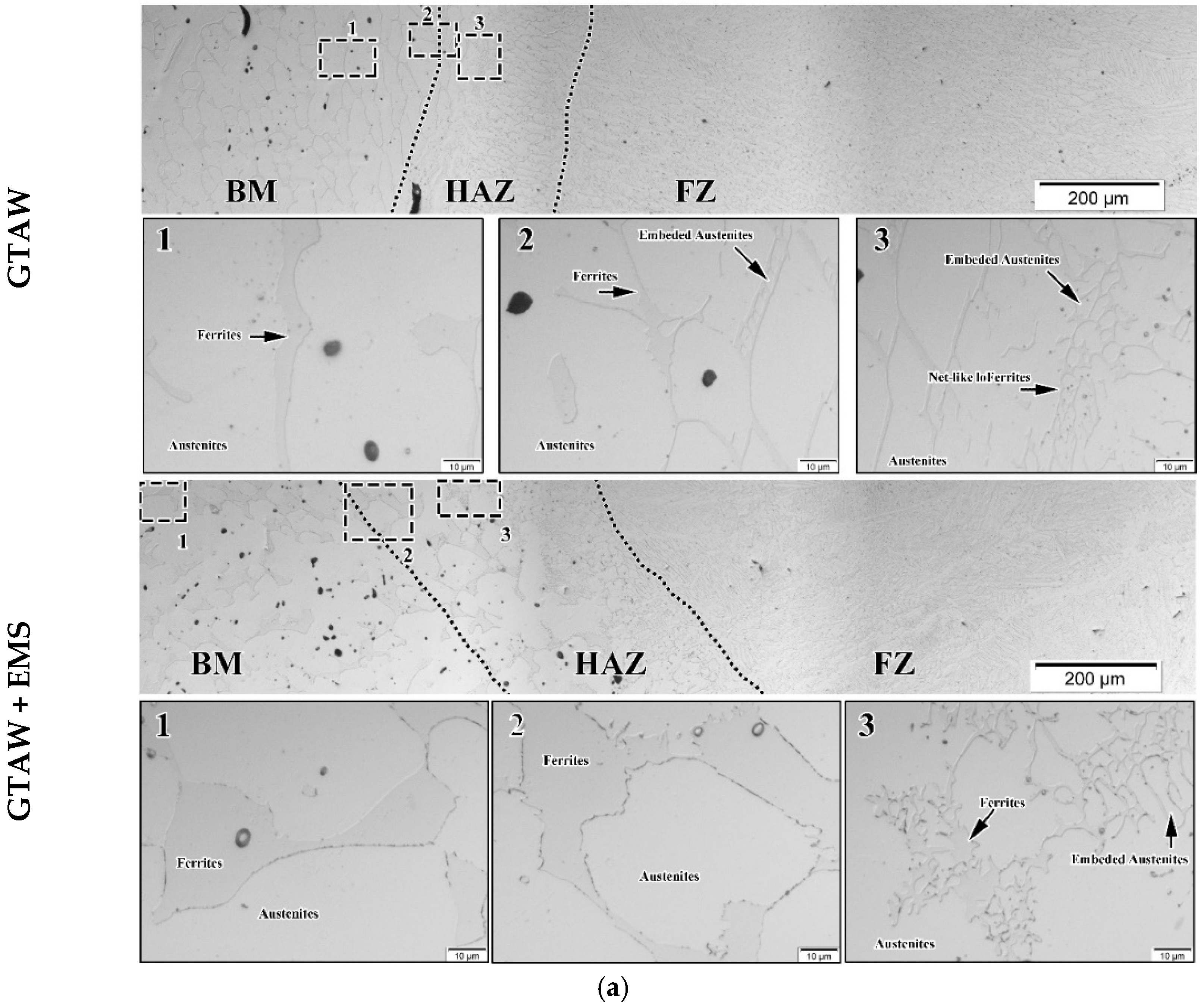
3.2. The Cross-Section of Welds
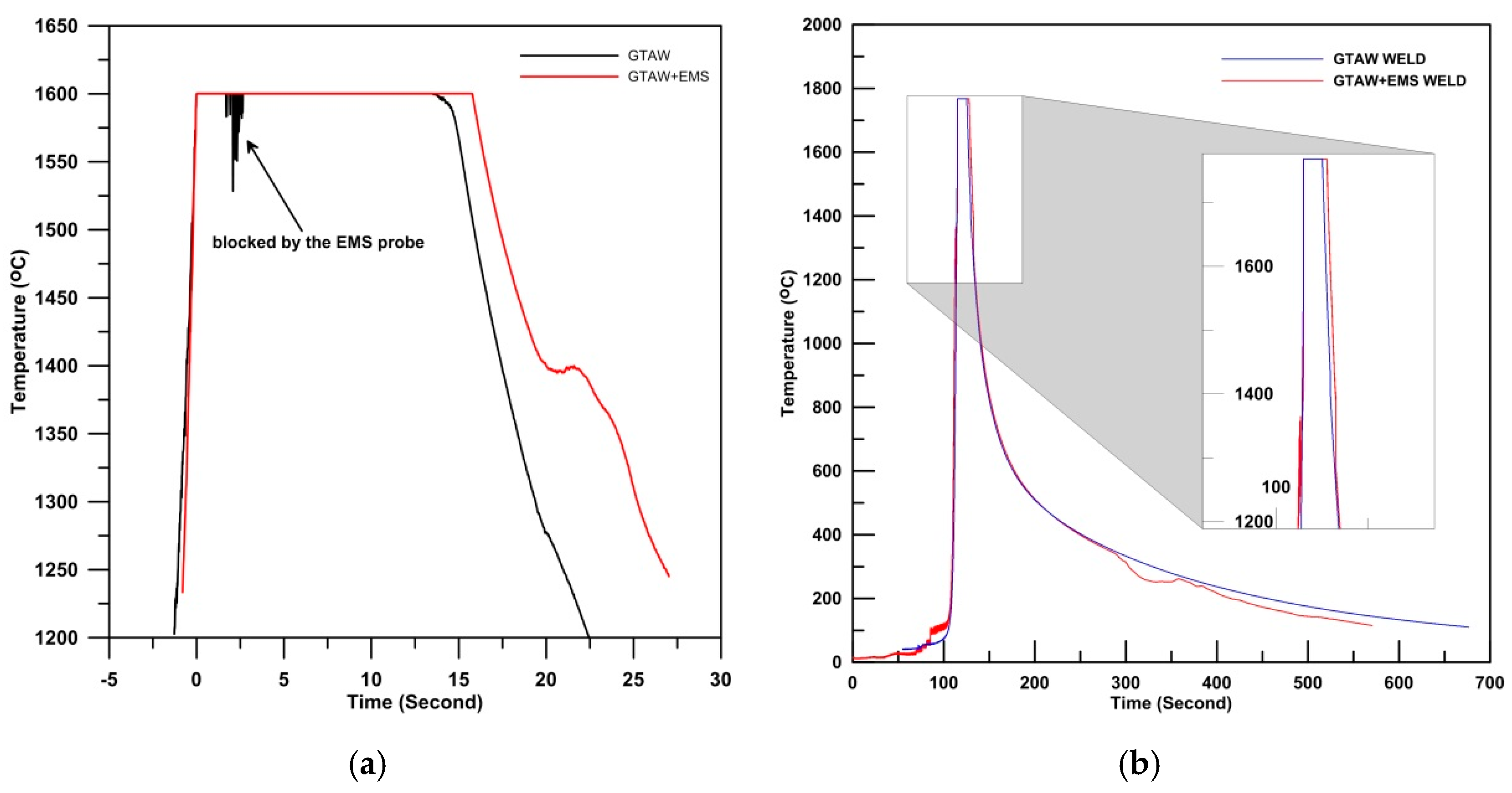
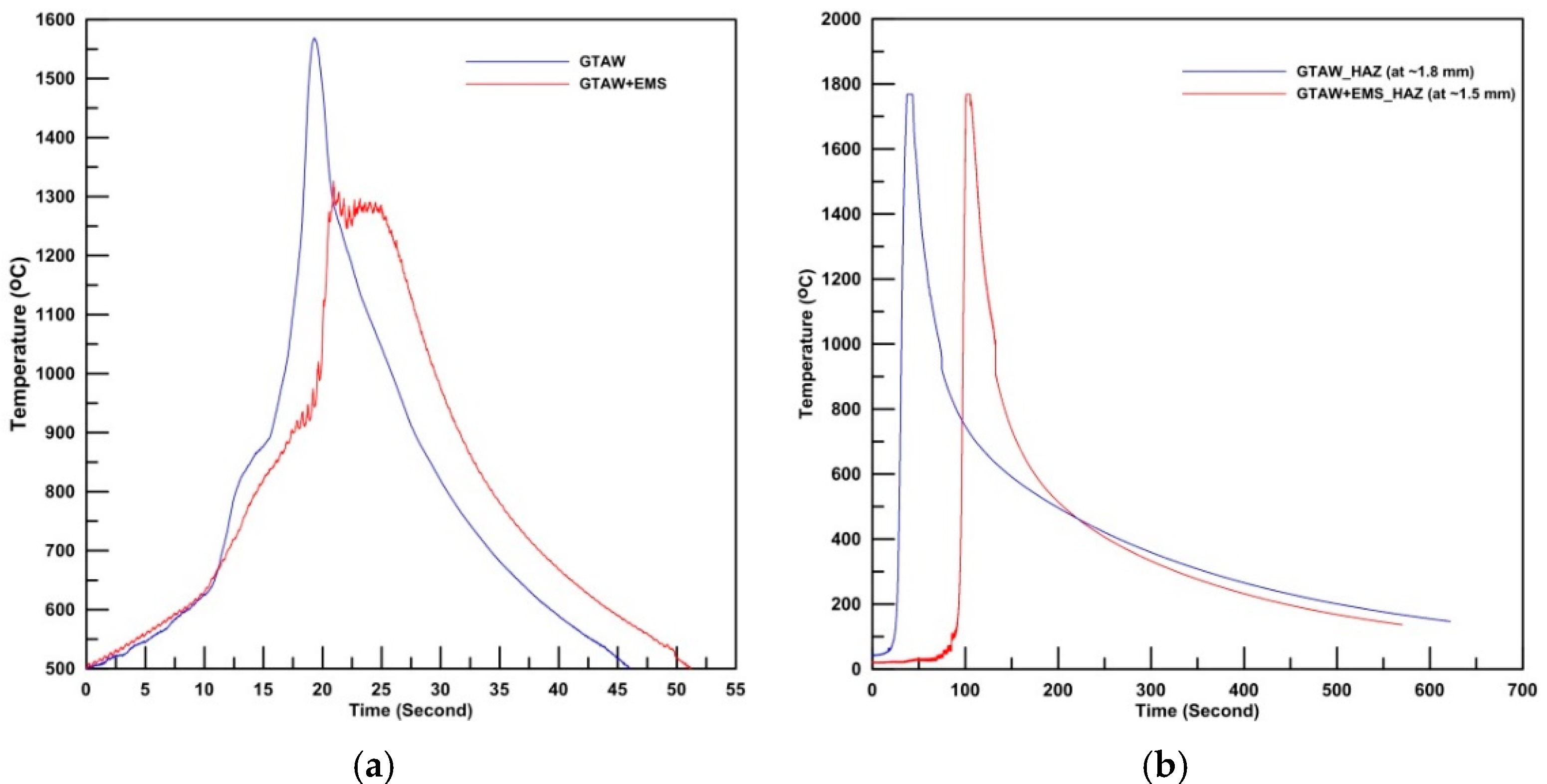
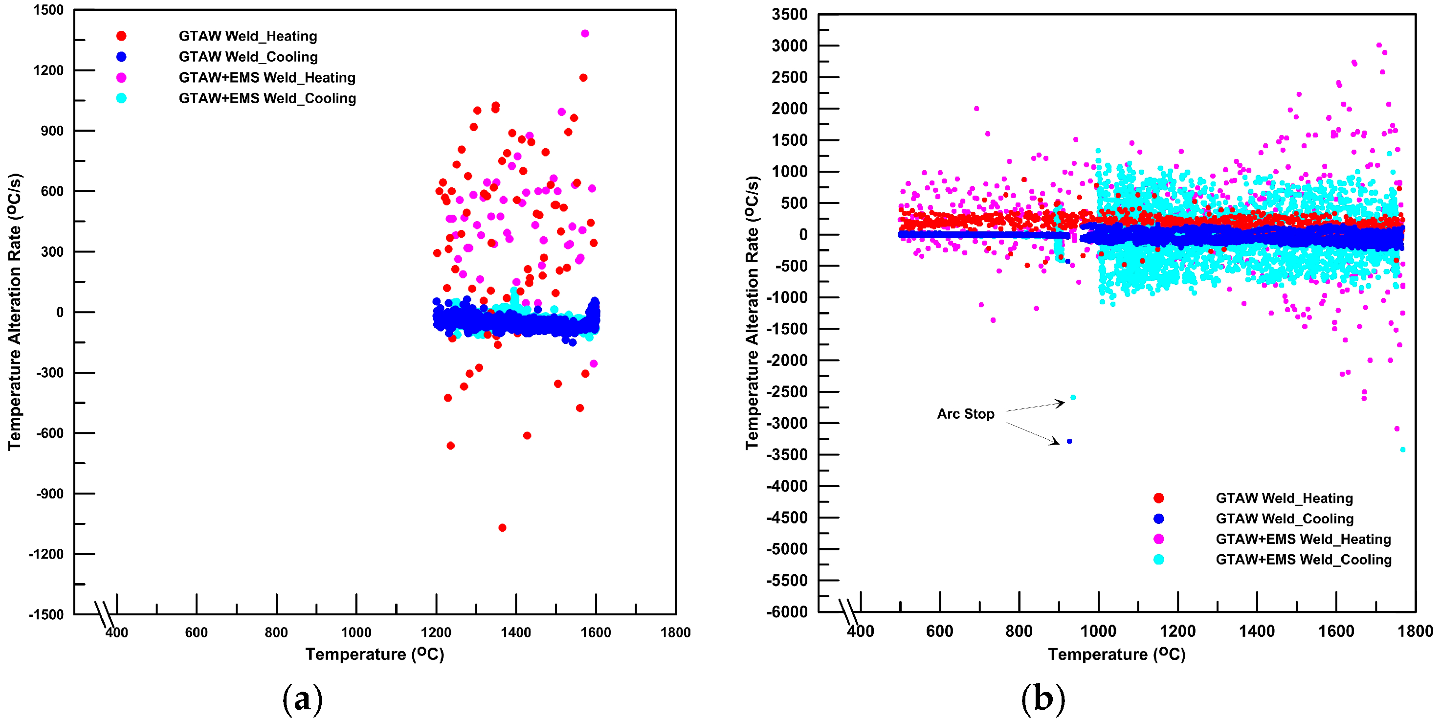
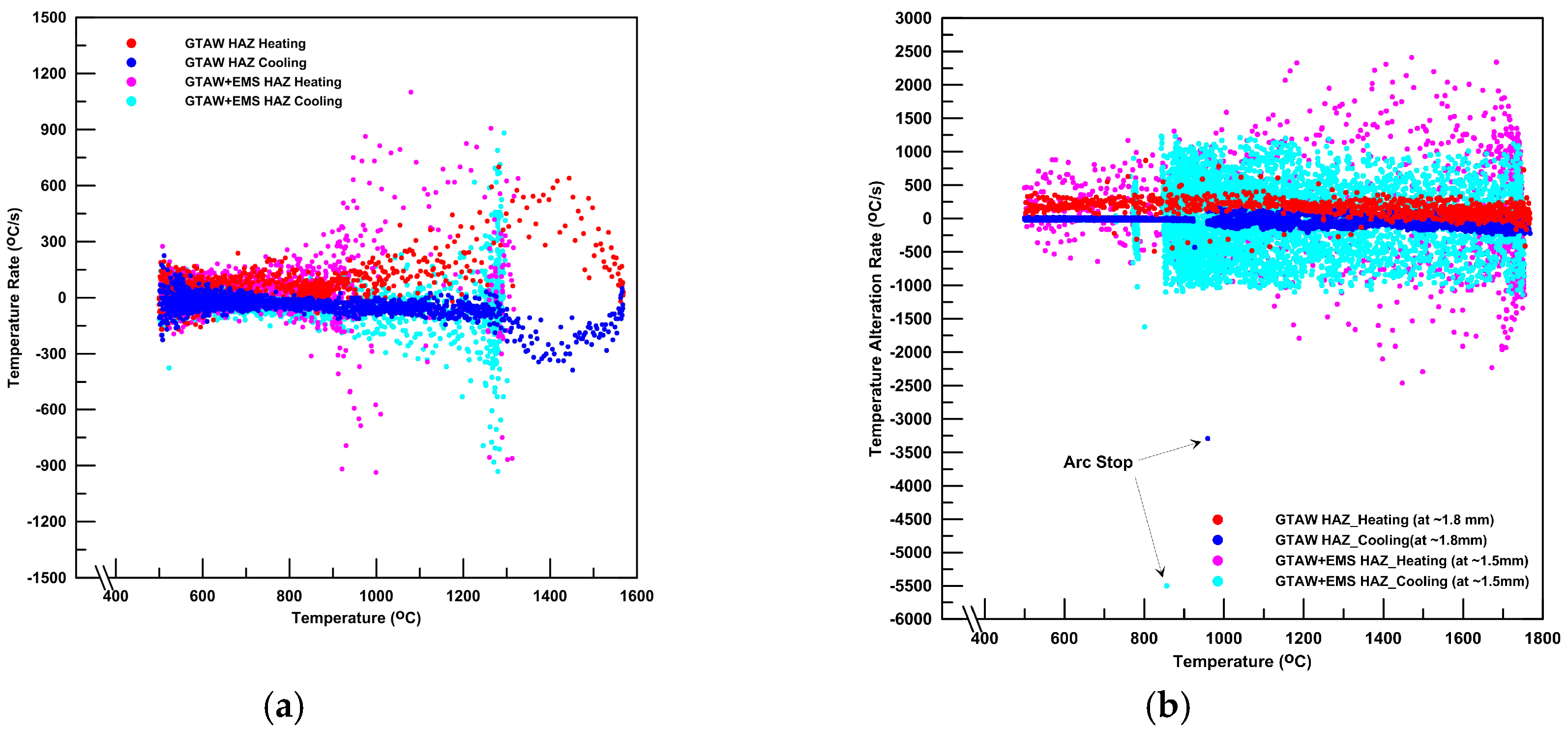
3.3. The Temperature Measurements of Welds
4. Discussion
5. Conclusions
Author Contributions
Funding
Conflicts of Interest
References
- Wei, P.S. The Physics of Weld Bead Defects. In Welding Processes; Kovacevic, R., Ed.; IntechOpen Limited: London, UK, 2012; pp. 395–414. [Google Scholar]
- Wang, J.; Sun, Q.; Zhang, T.; Zhang, S.; Liu, Y.; Feng, J. Arc characteristics in alternating magnetic field assisted narrow gap pulsed GTAW. J. Mater. Process. Technol. 2018, 254, 254–264. [Google Scholar] [CrossRef]
- Kutelu, B.J.; Seidu, S.O.; Eghabor, G.I. Review of GTAW Welding Parameters. J. Miner. Mater. Character. Eng. 2018, 6, 541–554. [Google Scholar] [CrossRef]
- Wu, H.; Chang, Y.; Lu, L.; Bai, J. Review on magnetically controlled arc welding process. Int. J. Adv. Manuf. Technol. 2017, 91, 4263–4273. [Google Scholar] [CrossRef]
- Wu, C.; Yang, F.; Gao, J. Effect of external magnetic field on weld pool flow conditions in high-speed gas metal arc welding. Proc. Inst. Mech. Eng. Part B J. Eng. Manuf. 2016, 230, 188–193. [Google Scholar] [CrossRef]
- Larquer, T.R.; Reis, R.P. Gas Tungsten Arc Welding with Synchronized Magnetic Oscillation. In Joining Technologies; Ishak, M., Ed.; IntechOpen: Rijeka, Croatia, 2016; Available online: https://www.intechopen.com/books/joining-technologies/gas-tungsten-arc-welding-with-synchronized-magnetic-oscillation (accessed on 30 October 2019).
- Su, Y.H.; Liu, Z.J.; Liu, D. Effect of Magnetic Field on Microstructure and Properties of Magnesium Alloy Welded Joint with GTAW. Adv. Mater. Res. 2011, 189, 3507–3510. [Google Scholar] [CrossRef]
- Jeng, S.L.; Su, D.P.; Lee, J.T.; Huang, J.Y. Effects of Electromagnetic Stirring on the Cast Austenitic Stainless Steel Weldments by Gas Tungsten Arc Welding. Metals 2018, 8, 630. [Google Scholar] [CrossRef]
- Saini, S.; Gupta, V.; Nagpal, R.; Gupta, R.; Kuday, V. A review on the effect of magnetic field on weld quality and weld geometry in arc welding. Int. J. Adv. Educ. Res. 2017, 2, 57–63. [Google Scholar]
- Yu, X.; Lim, Y.C.; Smith, R.; Babu, S.S.; Farson, D.F.; Lippold, J.C.; McCracken, S. Reducing hot cracking tendency of dissimilar weld overlay by magnetic arc oscillation. Mater. Sci. Technol. 2014, 30, 930–937. [Google Scholar] [CrossRef]
- Bachmann, M.; Avilov, V.; Gumenyuk, A.; Rethmeier, M. Experimental and Numerical Investigation of an Electromagnetic Weld Pool Support System for High Power Laser Beam Welding of Austenitic Stainless Steel. J. Mater. Process. Technol. 2014, 3, 578–591. [Google Scholar] [CrossRef]
- Ai, Y.; Jiang, P.; Wang, C.; Mi, G.; Geng, S.; Liu, W.; Han, C. Investigation of the Humping Formation in the High Power and High Speed Laser Welding. Optics Lasers Eng. 2018, 107, 102–111. [Google Scholar] [CrossRef]
- Üstündağ, Ö.; Avilov, V.; Gumenyuk, A.; Rethmeier, M. Improvement of Filler Wire Dilution Using External Oscillating Magnetic Field at Full Penetration Hybrid Laser-Arc Welding of Thick Materials. Metals 2019, 9, 594. [Google Scholar] [CrossRef]
- Watanabe, T.; Nakamura, H.; Ei, K. Grain refinement by TIG welding with electromagnetic stirring—A study of solidification control of austenitic stainless steel weld metal. Weld. Int. 1989, 3, 312–317. [Google Scholar] [CrossRef]
- Lim, Y.C.; Yu, X.; Cho, J.H.; Sosa, J.D.; Farson, F.; Babu, S.S.; McCracken, S.; Flesner, B. Effect of magnetic stirring on grain structure refinement Part 2—Nickel alloy weld overlays. Sci. Technol. Weld. Join. 2010, 15, 400–406. [Google Scholar] [CrossRef]
- Villafuerte, J.C.; Kerr, H.W. Electromagnetic Stirring and Grain Refinement in Stainless Steel GTA Welds. Weld. J. 1990, 1, 1s–13s. [Google Scholar]
- Liu, Y.; Sun, Q.; Liu, J.; Wang, S.; Feng, J. Effect of axial external magnetic field on cold metal transfer welds of aluminum alloy and stainless steel. Mater. Lett. 2015, 152, 29–31. [Google Scholar] [CrossRef]
- Vollertsen, F.; Thomy, C. Magnetic Stirring during Laser Welding of Aluminum. J. Laser Appl. 2006, 18, 28–34. [Google Scholar] [CrossRef]
- Kou, S.; Le, Y. Grain Structure and Solidification Cracking in Oscillated Arc Welds of 5052 Aluminum Alloy. Metal. Trans. A 1985, 16, 1345–1352. [Google Scholar] [CrossRef]
- Malinowski-Brodnicka, M.; Ouden, G.D.; Vink, W.J.P. Effect of Electromagnetic Stirring on GTA Welds in Austenitic Stainless Steel. Weld. J. 1990, 91, 52s–59s. [Google Scholar]
- Sivaprasad, K.; Ganesh, S. Influence of Magnetic Arc Oscillation and Current Pulsing on Fatigue Behavior of Alloy 718 TIG Weldments. Mater. Sci. Eng. A 2007, 448, 120–127. [Google Scholar] [CrossRef]
- Lim, Y.C.; Yu, X.; Cho, J.H.; Sosa, J.D.; Farson, F.; Babu, S.S.; McCracken, S.; Flesner, B. Effect of magnetic stirring on grain structure refinement: Part 1—Autogenous nickel alloy welds. Sci. Technol. Weld. Join. 2010, 15, 583–589. [Google Scholar] [CrossRef]
- Bachmann, M.; Avilov, V.; Gumenyuk, A.; Rethmeier, M. About the influence of a steady magnetic field on weld pool dynamics in partial penetration high power laser beam welding of thick aluminum parts. Int. J. Heat Mass Transf. 2013, 60, 309–321. [Google Scholar] [CrossRef]
- Wang, L.; Wu, C.; Chen, J.; Gao, J. Influence of the external magnetic field on fluid flow, temperature profile and humping bead in high speed gas metal arc welding. Int. J. Heat Mass Transf. 2018, 116, 1282–1291. [Google Scholar] [CrossRef]
- Yudodibroto, B.Y. The Effect of Electro-Magnetic Stirring on the Weld Microstructure of Aluminum Alloys. Master’s Thesis, Delft University of Technology, Delft, The Netherlands, 2000. [Google Scholar]
- Kuo, S. Welding Metallurgy, 1st ed.; John Wiley & Sons: New York, NY, USA, 1987; pp. 91–99. [Google Scholar]
- Kotecki, D.J.; Cheever, D.L.; Howden, D.G. Mechanism of Ripple Formation During Weld Solidification. Weld. J. 1972, 8, 386s–391s. [Google Scholar]
- Xiao, Y.H.; DenOuden, G. Weld Pool Oscillation during GTA Welding of Mild Steel The oscillation behavior of the GTA weld pool depends on the welding conditions and can be used for in-process control of weld penetration. Weld. J. 1993, 72, 428s–434s. [Google Scholar]
- Yudodibroto, B.Y.B. Liquid Metal Oscillation and Arc Behaviour during Welding. Ph.D. Thesis, Delft University of Technology, Delft, The Netherlands, 25 January 2010. [Google Scholar]
- Nomura, K.; Ogino, Y.; Hirata, Y. Shape Control of TIG Arc Plasma by Cusp Type Magnetic Field with Permanent Magnets. Q. J. Jpn. Weld. Soc. 2009, 27, 170–175. [Google Scholar] [CrossRef][Green Version]
- Janaki Ram, G.D.; Murugesan, R.; Sundaresan, S.J. Fusion zone grain refinement in aluminum alloy welds through magnetic arc oscillation and its effect on tensile behavior. J. Mater. Eng. Perform. 1999, 8, 513–520. [Google Scholar] [CrossRef]
- McCracken, S.; Willis, E. Welding Issues: Alloy 52 Weldability & Testing; Magnetic Stir Welding; Laser & Friction Stir Welding on Irradiated Material. In Proceedings of the NRC/Industry Technical Meeting, Rockville, MD USA, 9 June 2011; Available online: https://www.nrc.gov/docs/ML1116/ML11167A261.pdf (accessed on 30 October 2019).
- Kung, C.Y.; Yu, G.P.; Huang, J.H.; Jeng, S.L. The effect of electromagnetic stirring on the microstructure and mechanical properties of 309L stainless steel welds. In Proceedings of the 10th International Conference on Trends in Welding Research and 9th International Welding Symposium of Japan Welding Society (9WS), Tokyo, Japan, 11–14 October 2016. [Google Scholar]
- Kung, C.Y.; Jeng, S.L. Effects of Magnetic-Stirring on the Austenitic Stainless Steel Welds; INER report (INER-11704R); Institute of Nuclear Energy Research: Taoyuan, Taiwan, 2015. [Google Scholar]
- Pearce, B.P.; Kerr, H.W. Grain refinement in magnetically stirred GTA welds of aluminum alloys. Metall. Trans. B 1981, 12, 479–486. [Google Scholar] [CrossRef]


| Metal | C | Mn | P | S | Si | Cr | Ni | Mo | Cu | Nb | Other |
|---|---|---|---|---|---|---|---|---|---|---|---|
| CF8A | 0.049 | 0.43 | 0.035 | 0.03 | 0.45 | 18.37 | 8.12 | 0.28 | 0.34 | - | - |
| 308L | 0.018 | 1.57 | 0.019 | 0.005 | 0.703 | 19.520 | 9.698 | 0.111 | 0.136 | - | 0.010 |
| Specimen | Test | Rp (µm) | Rv (µm) | Rz (µm) | Ra (µm) | Rq (µm) |
|---|---|---|---|---|---|---|
| GTAW | 1 | 37.663 | 28.793 | 66.456 | 6.35 | 8.602 |
| 2 | 36.214 | 25.645 | 61.859 | 5.664 | 7.691 | |
| 3 | 34.798 | 36.278 | 71.076 | 6.355 | 8.707 | |
| Average | 36.225 | 30.239 | 66.464 | 6.123 | 8.333 | |
| SD | 1.433 | 5.462 | 4.609 | 0.398 | 0.559 | |
| GTAW + EMS | 1 | 38.621 | 11.537 | 50.158 | 3.153 | 5.105 |
| 2 | 35.513 | 11.307 | 46.821 | 2.944 | 4.678 | |
| 3 | 40.369 | 9.988 | 50.357 | 3.299 | 5.879 | |
| Average | 38.168 | 10.944 | 49.112 | 3.132 | 5.221 | |
| SD | 1.679 | 0.299 | 1.707 | 0.115 | 0.286 |
| Weld | Dilution (%) | Contact Angle | Bead Height (mm) | Bead Width (mm) | P/W | ||
|---|---|---|---|---|---|---|---|
| R | P | Total | |||||
| GTAW | 47.8 | 53–67 | 2.17 | 2.00 | 4.17 | 8.80 | 0.227 |
| GTAW + EMS | 30.7 | 74–75 | 2.82 | 1.33 | 4.15 | 8.26 | 0.161 |
| Location | Period | Specimen | Temperature Alteration Rates (°C/s) | ||||
|---|---|---|---|---|---|---|---|
| POS (%) | NEG (%) | Ratio * | Max/Min | ||||
| Interior (Thermal Couple) | Heating | GTAW | FZ | 83.9 | 13.1 | 6.40 | 730/−410 |
| HAZ | 87.9 | 10.0 | 8.79 | 870/−490 | |||
| GTAW + EMS | FZ | 63.8 | 35.7 | 1.79 | 3010/−3090 | ||
| HAZ | 50.9 | 48.9 | 1.04 | 2410/−2460 | |||
| Cooling | GTAW | FZ | 30.3 | 67.0 | 0.45 | 140/−240 | |
| HAZ | 22.5 | 64.8 | 0.35 | 160/−430 | |||
| GTAW + EMS | FZ | 34.0 | 61.0 | 0.56 | 1330/−3420 | ||
| HAZ | 47.2 | 52.2 | 0.90 | 1120/−1120 | |||
| Surface (Pyrometer) | Heating | GTAW | FZ | 76.0 | 24.0 | 3.17 | 1162/−1068 |
| HAZ | 87.6 | 7.7 | 11.38 | 700/−81 | |||
| GTAW + EMS | FZ | 97.4 | 2.4 | 40.58 | 1381/−256 | ||
| HAZ | 60.9 | 35.3 | 1.73 | 1100/−937 | |||
| Cooling | GTAW | FZ | 7.4 | 90.6 | 0.08 | 56/−150 | |
| HAZ | 1.9 | 95.6 | 0.02 | 50/−386 | |||
| GTAW + EMS | FZ | 11.8 | 83.7 | 0.14 | 106/−125 | ||
| HAZ | 31.3 | 64.4 | 0.49 | 881/−931 | |||
© 2020 by the authors. Licensee MDPI, Basel, Switzerland. This article is an open access article distributed under the terms and conditions of the Creative Commons Attribution (CC BY) license (http://creativecommons.org/licenses/by/4.0/).
Share and Cite
Jeng, S.-L.; Su, D.-P.; Lee, J.-T.; Huang, J.-Y. The Impact of EMS on the Temperature Fluctuations, Appearance, and Microstructure of GTA Stainless Steel Welds. Metals 2020, 10, 118. https://doi.org/10.3390/met10010118
Jeng S-L, Su D-P, Lee J-T, Huang J-Y. The Impact of EMS on the Temperature Fluctuations, Appearance, and Microstructure of GTA Stainless Steel Welds. Metals. 2020; 10(1):118. https://doi.org/10.3390/met10010118
Chicago/Turabian StyleJeng, Sheng-Long, Dai-Ping Su, Jing-Ting Lee, and Jiunn-Yuan Huang. 2020. "The Impact of EMS on the Temperature Fluctuations, Appearance, and Microstructure of GTA Stainless Steel Welds" Metals 10, no. 1: 118. https://doi.org/10.3390/met10010118
APA StyleJeng, S.-L., Su, D.-P., Lee, J.-T., & Huang, J.-Y. (2020). The Impact of EMS on the Temperature Fluctuations, Appearance, and Microstructure of GTA Stainless Steel Welds. Metals, 10(1), 118. https://doi.org/10.3390/met10010118