Article

An Identification Method for Orifice-Type Restrictors Based on the Closed-Form Solution of Reynolds Equation

Politecnico di Torino, Corso Duca degli Abruzzi 24, 10129 Turin, Italy
*
Author to whom correspondence should be addressed.
Lubricants 2021, 9(5), 55; https://doi.org/10.3390/lubricants9050055
Submission received: 5 February 2021 / Revised: 3 April 2021 / Accepted: 30 April 2021 / Published: 11 May 2021

Abstract

:
Even though the behavior of aerostatic bearings has for long been the topic of extensive research, there are still many aspects that require further investigation. Among these, the identification of the discharge coefficients is one the most crucial. This paper presents a hybrid method to identify the discharge coefficients of aerostatic bearing orifices. The method is termed as hybrid since it exploits experimental data and the equations of the analytical model of a circular and centrally fed aerostatic pad. The obtained results demonstrate the accuracy of the method. The proposed method further offers practical advantages compared to the conventional methods.

1. Introduction

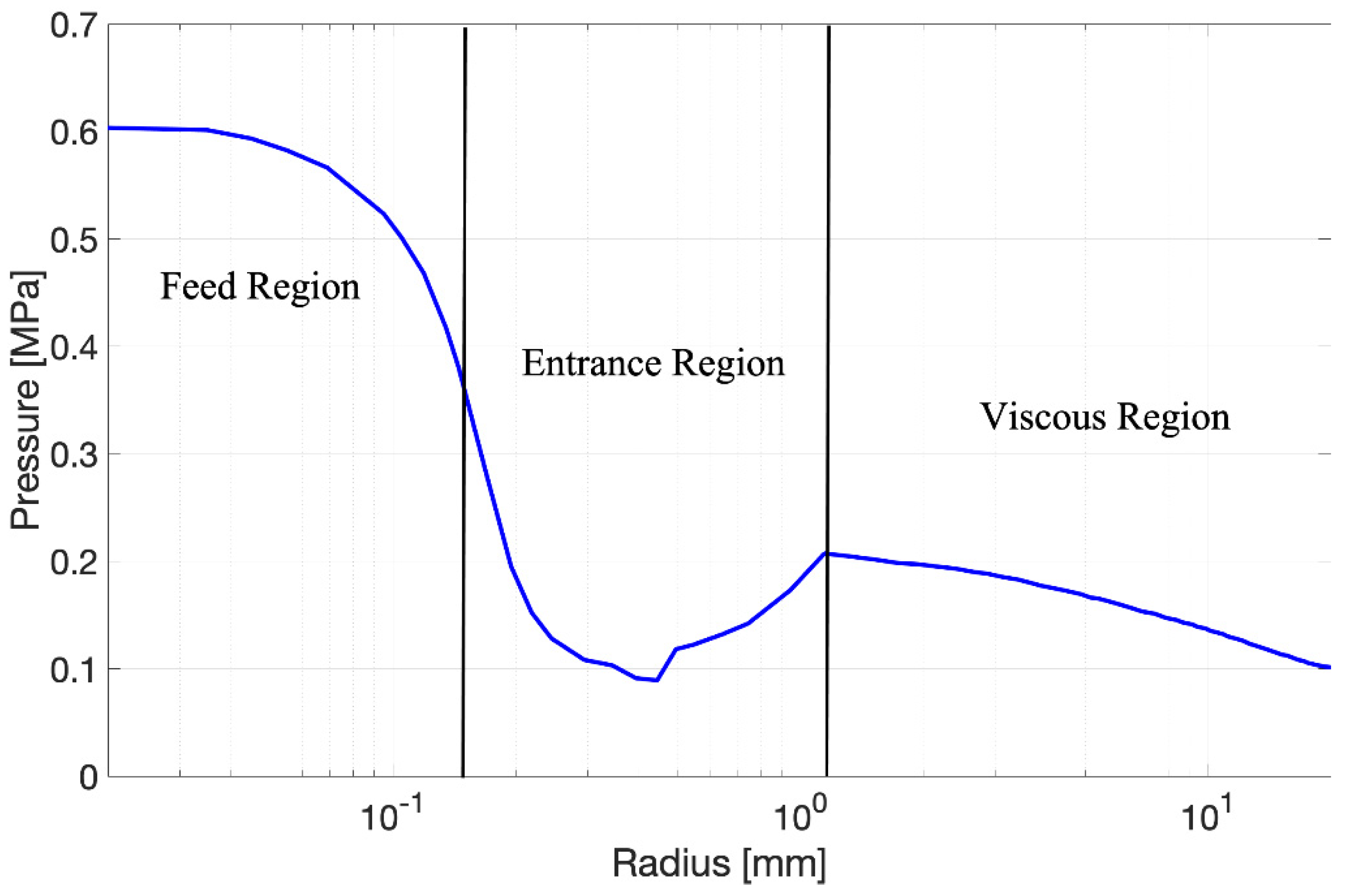
Due to their low friction, reliability, long life and ability to operate at extreme temperatures, aerostatic bearings are the premier choice for many high speed and high precision industrial applications, e.g., bore grinding, precision milling, micro-machining, machine tools and measuring machines [1]. Even though the behavior of aerostatic bearings has for long been the topic of extensive research, there are still many aspects that require further investigation. Among these, the prediction of the entrance flow effects near the bearing feeding sources is one of the most crucial [2]. It is well known that the flow field in the air gap film may be simplified by considering three subregions depending on their different characteristics [3,4]. Starting from the plenum chamber of the bearing, it is possible to distinguish a feed, entrance and a viscous flow region. Due to the relatively large dimension of the plenum chamber, here, the fluid can be reasonably assumed to be at rest. From this chamber, the fluid flow quickly accelerates through the supply hole of the bearing till reaching its maximum velocity at an annular curtain area close to the gap entrance. In this region, conventionally identified as the feed region, the inertial effects are dominant compared to the viscous ones, due to the high velocity characterizing the fluid flow. Thereafter, the fluid flow gradually decelerates at the clearance walls, due to the growth of the boundary layers; as a whole, this is due to the increasing of the annular cross-section of the air gap. This growth of the boundary layers increases the magnitude of the viscous effects that gradually become dominant compared to the inertial ones. It was found that, in some cases, in the region where viscous and inertial effects are equally important, i.e., the entrance region, vorticity and supersonic flow can occur [5,6,7]. These complex phenomena become apparent through a peculiar trough and subsequent crest of the mean pressure profile. The zone which is downstream of this pressure crest corresponds to the viscous region, where inertial effects become negligible compared to the viscous ones and the fluid flow exhibits an almost parabolic velocity profile. Even though the entrance region extends for only a small portion of the air gap, due to the pressure depression phenomenon [6,8], it is highly influential for the accurate prediction of the performance of aerostatic bearings. To solve this problem rigorously, the compressible Navier-Stokes, energy and continuity equations should be simultaneously solved. Performing Computational Fluid Dynamics (CFD) simulations is the only way to obtain highly accurate predictions, since there are no closed-form formulations. Due to the considerable computational cost of CFD simulations, the use of the Reynolds equation to obtain the pressure distribution in the viscous region and a lumped formulation to compute a theoretical value of the pressure at the air gap entrance ( p t h ) is now universally recognized as a standard. However, this approach can provide satisfactory results, if and only if, the adopted lumped formulation is integrated with suitable correction coefficients that are known as discharge coefficients. Discharge coefficients are defined as the ratio between the actual mass flow rate to the ideal flow rate computed by means of the Euler equation. Even though many researchers have defined the supply hole discharge coefficients as a constant value, a lot of experimental and numerical works have demonstrated that, especially for aerostatic pads, these coefficients can vary significantly with the supply hole geometry, pressure ratio, Mach and Reynolds number. Chang et al. [9,10] used a CFD model to identify the discharge coefficients of a centrally fed circular pad considering different values of the orifice diameter and the supply pressure. The values of the theoretical downstream pressure p t h were computed by minimizing the relative error between the load capacity obtained through the CFD simulations and a finite difference model (FDM). Moreover, the authors used neural networks to express discharge coefficients as a function of the film thickness and the supply orifice dimensions. Mitayatake and Yoshimoto [11] used the same numerical approach to compute the discharge coefficients of small feed holes. Since the simulated results showed that the air flow was restricted both at the entrance of the feed holes and the air gap, they assumed that two discharge coefficients had to be considered at these two positions. Subsequently, this approach was validated by Nishio et al. in [12] and, Renn and Hsiao [13] studied the mass flow-rate characteristic of aerostatic bearings by experimental and numerical approaches. They identified the mass flow rate characteristic of feed holes by using the formula provided in ISO 6358. They found that the critical pressure ratio of orifice restrictor is in the range 0.35–0.4 instead of 0.5283 and that the discharge coefficients can be assumed equal to 0.84.
Along with CFD simulations, solving the laminar boundary layer equation through the method of “separation of variable” (MSV), proposed by Al-Bender and Van Brussel [14], is another numerical approach that was exploited to identify the discharge coefficients of aerostatic bearing restrictors. Through this method, Waumans et al. [3] computed the discharge coefficients for different restrictors and air gap geometries. They used the pressure profile computed through the MSV method to identify the theoretical downstream pressures p t h which are used to compute discharge coefficients. Additionally, they expressed the discharge coefficients as a function of an entrance number and the pressure ratio of the bearing restrictor. Similarly, Zhang et al. [15] used the MSV method to study the influence of the orifice diameter and the bearing supply pressure on discharge coefficients. Even though more expensive, the use of experimental data can be another way to identify the discharge coefficients of aerostatic bearing restrictors. Belforte et al. [16] performed an experimental identification by considering different orifice diameters, air gap heights and supply pressures. The identified coefficients were computed by using the nozzle/orifice formula and considering as p t h the pressure crest downstream to the entrance region. Moreover, they proposed an empirical formula for inherent and orifice-type restrictors where discharge coefficients are expressed as a function of the Reynolds number and the ratio of the air gap height to the orifice diameter. The accuracy of this formulation was also experimentally validated both for supply holes with conventional diameters (0.2–0.4 mm) and micro holes (<0.1 mm). Even though this formulation reveals good accuracy, the adopted experimental approach may result as impractical when the supply hole diameters are smaller than 0.2 mm. In view of this, Belforte et al. [17] proposed a hybrid approach which combines both theoretical and experimental results. This method consists in measuring only one experimental point of the air gap pressure profile and using the bisection method to iterate the numerical discharge coefficient value of a Finite Difference Model (FDM) of the pad until the error between the numerical and the measured pressures is less than 0.2%.
Even though many of the described experimental and numerical approaches exhibit a sufficient level of accuracy, it must be considered that companies are constantly looking for more accurate models and bearings with higher performance. In view of, the constant increase of the performance of current experimental equipment, there could be room for improvements in developing new hybrid identification method for discharge coefficients.
On the basis of these considerations, this work presents a hybrid identification method which exploits experimental data and the analytical equations (closed-form solution) for circular and centrally fed aerostatic pads. The equations of the closed-form formulation are used in combination with the experimental data measured (through an improved version of a test bench described in a previous work [16]) in the viscous flow region to compute the theoretical downstream pressure p t h and the related values of the orifice discharge coefficients.

2. Materials and Methods

2.1. Pad Geometry

Figure 1a,b show a scheme and a photograph of the circular pad used in this study. As can be seen, the circular pad is centrally fed through a simple orifice. The nominal radius of the pad and its orifice diameter are 20 and 0.3 mm, respectively.
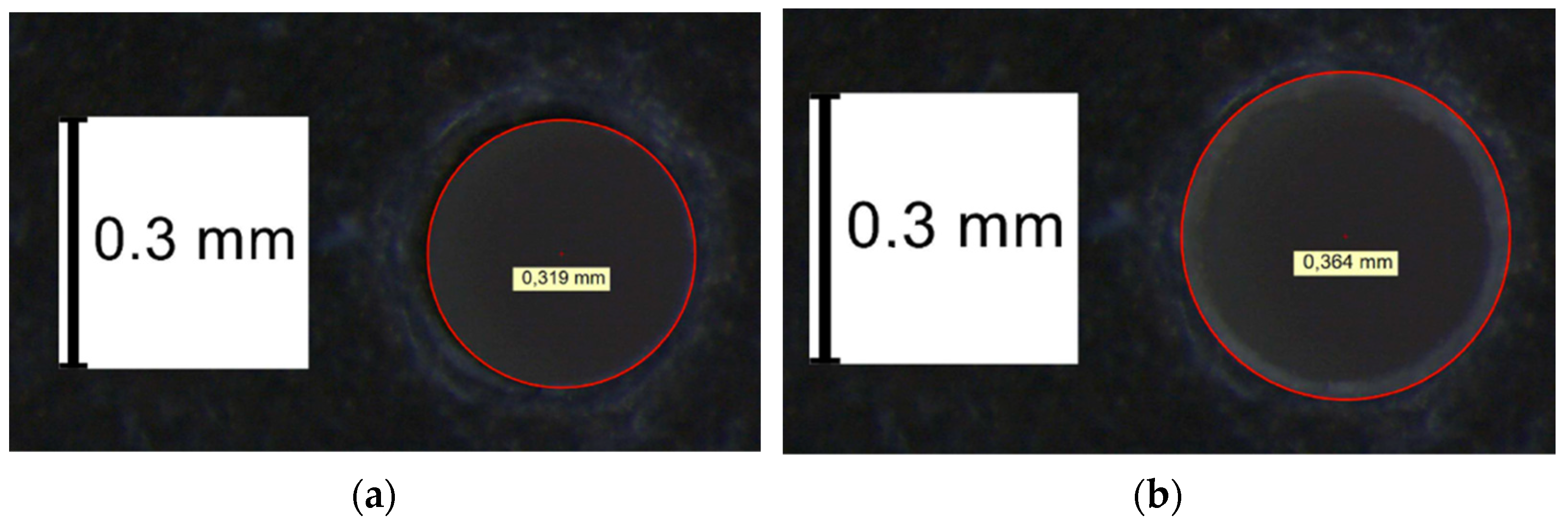
The orifice diameter of the pad was experimentally measured via an electronic microscope, to confirm its actual value and verify the presence of chamfers. Figure 2a,b shows the images acquired through the electronic microscope. These reveal that the orifice presents a diameter of 0.319 mm and a small chamfer.
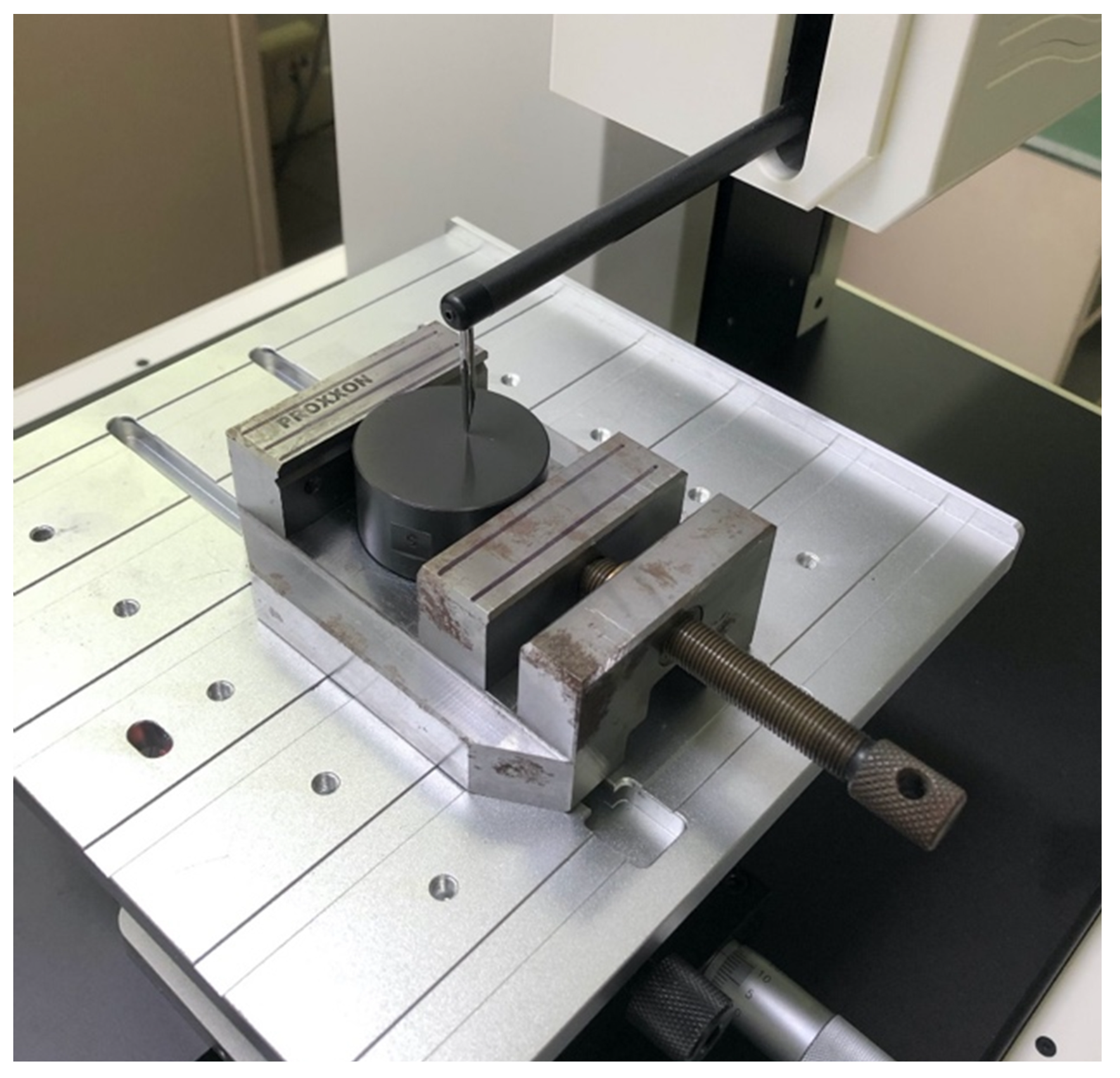
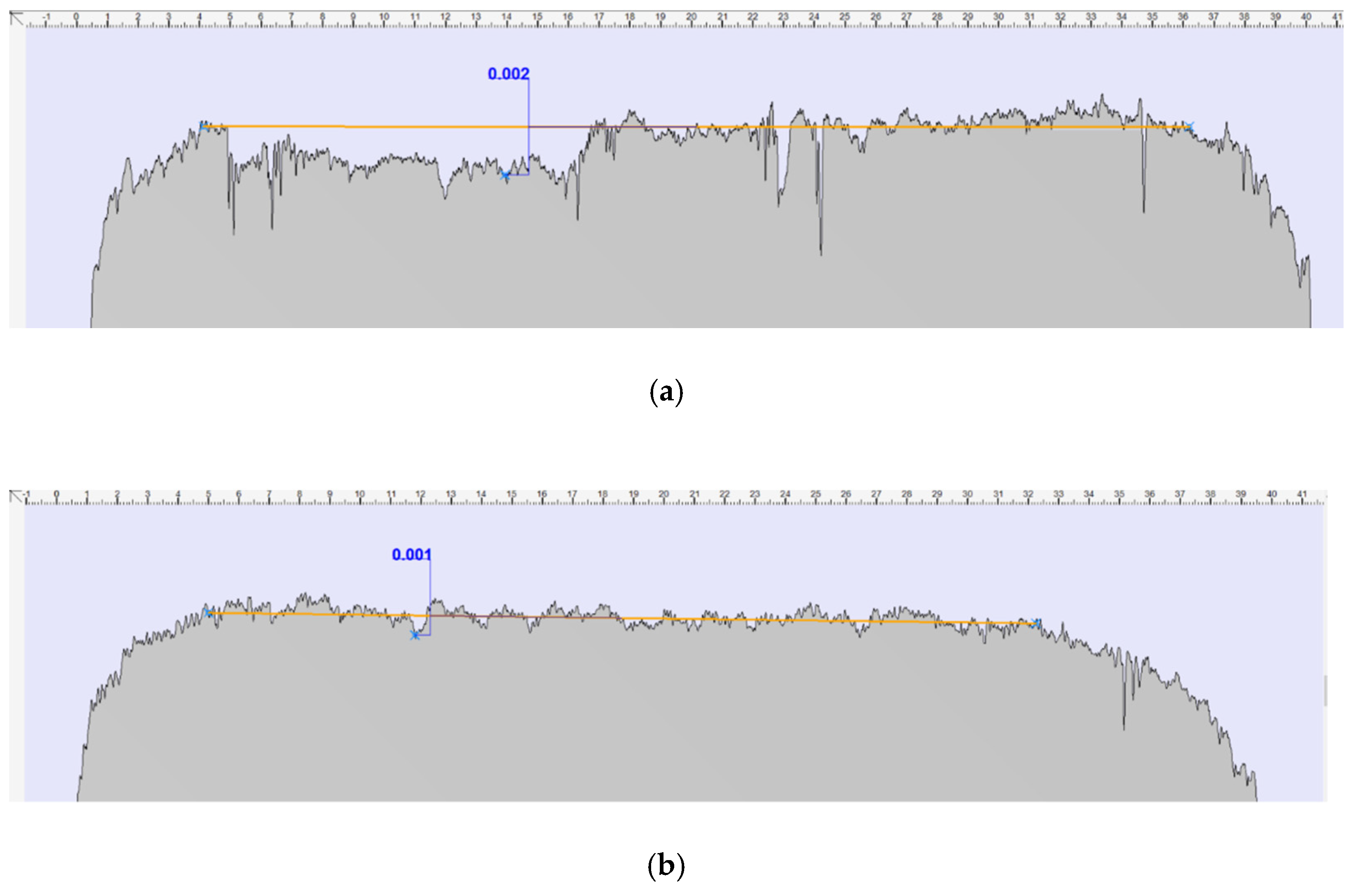
The geometry of the pad was further investigated by measuring its active (lower) surface through a stylus profilometer (see Figure 3). The profile of the pad was measured along two radial directions, respectively perpendicular. The first radial direction was oriented towards the supply duct of the pad and the second radial direction was perpendicular to the first. Figure 4a,b shows the results of these experimental measurements.
The maximum flatness error was of about ± 1 μ m and it was evidenced in the first measurement. This kind of experimental measure is important in order to use a correct mathematical formulation (see Section 2.5), e.g., if the pad presents a concave or convex surface.

2.2. Test Bench

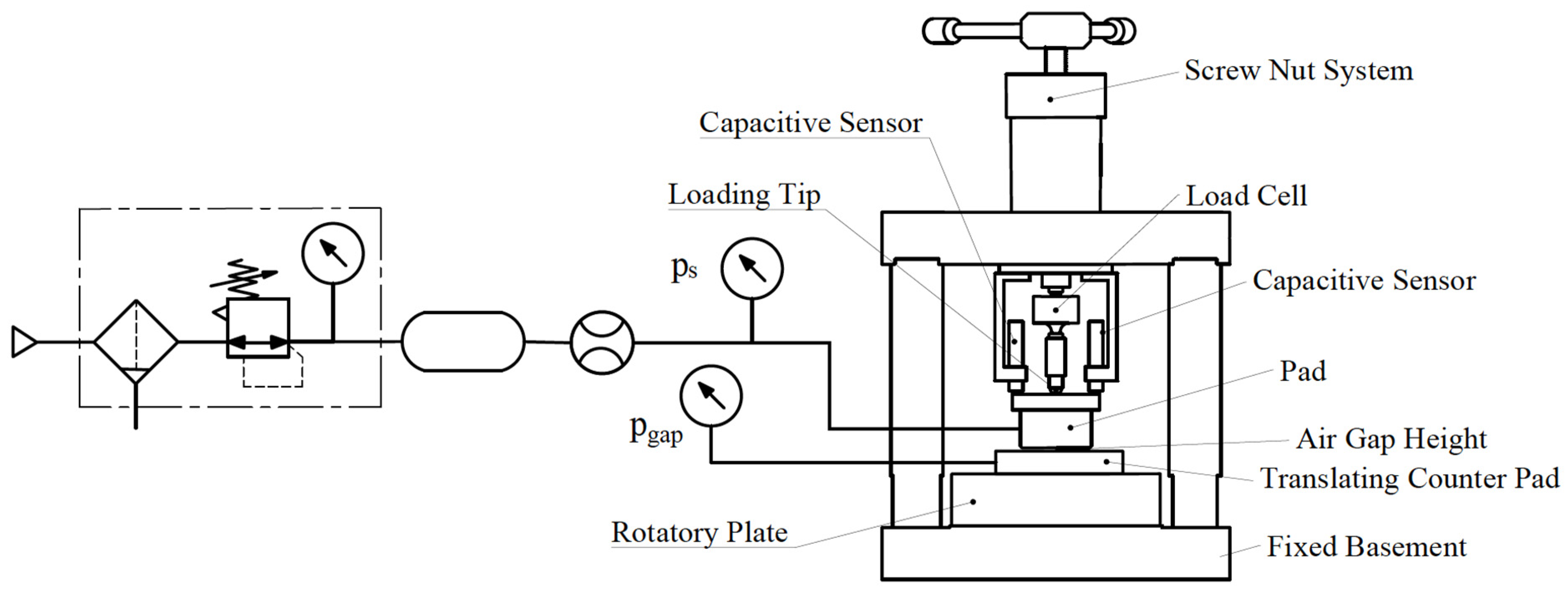
Figure 5 shows a scheme of the experimental apparatus used. This test bench was designed to measure both the static performance, i.e., load capacity and air consumption and the air gap pressure profile of aerostatic pads. The external load was applied through a vertical loading chain composed of a screw nut system (thread pitch: 0.1 mm), a load cell (HBM-U9C 200 N) and a loading tip. To allow the pad to tilt, the end of the loading tip had a spherical interface paired with a spherical housing machined on the center of the upper surface of the pad. During each test, the load applied to the pad and its air consumption were measured by means of the load cell and a digital flowmeter (FESTO SFAH-5U-Q6S-PNLK-PNVBA-M8 and SFAH-1U-Q6S-PNLK-PNVBA-M8). The air gap height was indirectly assessed by considering the relative displacement of the pad in the presence and absence of supply air. The pad displacement was measured by means of three symmetrically placed displacement capacitive sensors (Microepsilon CapaNDCT sensor CS05, Controller DT6220, Preamplifier DL6220/ECL2) fixed on a sensor holder above the upper surface of the pad. Measurement of the air gap pressure distribution was made possible by the presence of two stacked plates: a rotatory plate and a translating counterpad. The air gap pressure was measured through a pressure intake drilled onto the translating counterpad. The position of this pressure intake was defined on the basis of a polar reference frame ( r , θ , z ) whose origin corresponded to the center of the rotatory plate. The radial coordinate r was modified by translating the counter pad on the rotatory plates via a micrometer (MITUTOYO Micrometric Head, Heavy Duty, 8 mm Spindle 0–25 mm). Meanwhile, the angular coordinate θ was adjusted by rotating the rotatory plates around its center. The radial motion of the counterpad was obtained thanks to the presence of a prismatic guide on the rotatory plate, whereas the angular rotation was obtained thanks to a cylindrical coupling between the rotatory plate and the fixed basement. In this instance, due to the axial symmetry of the pad, the pressure distribution was measured by varying only the radial position of the pressure intake.
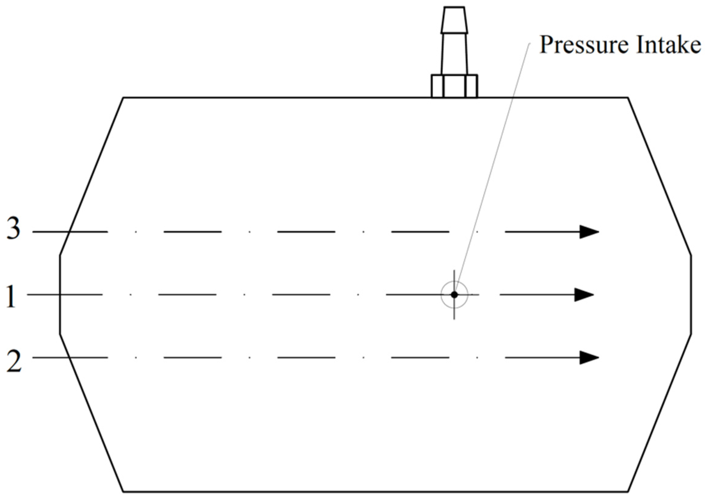
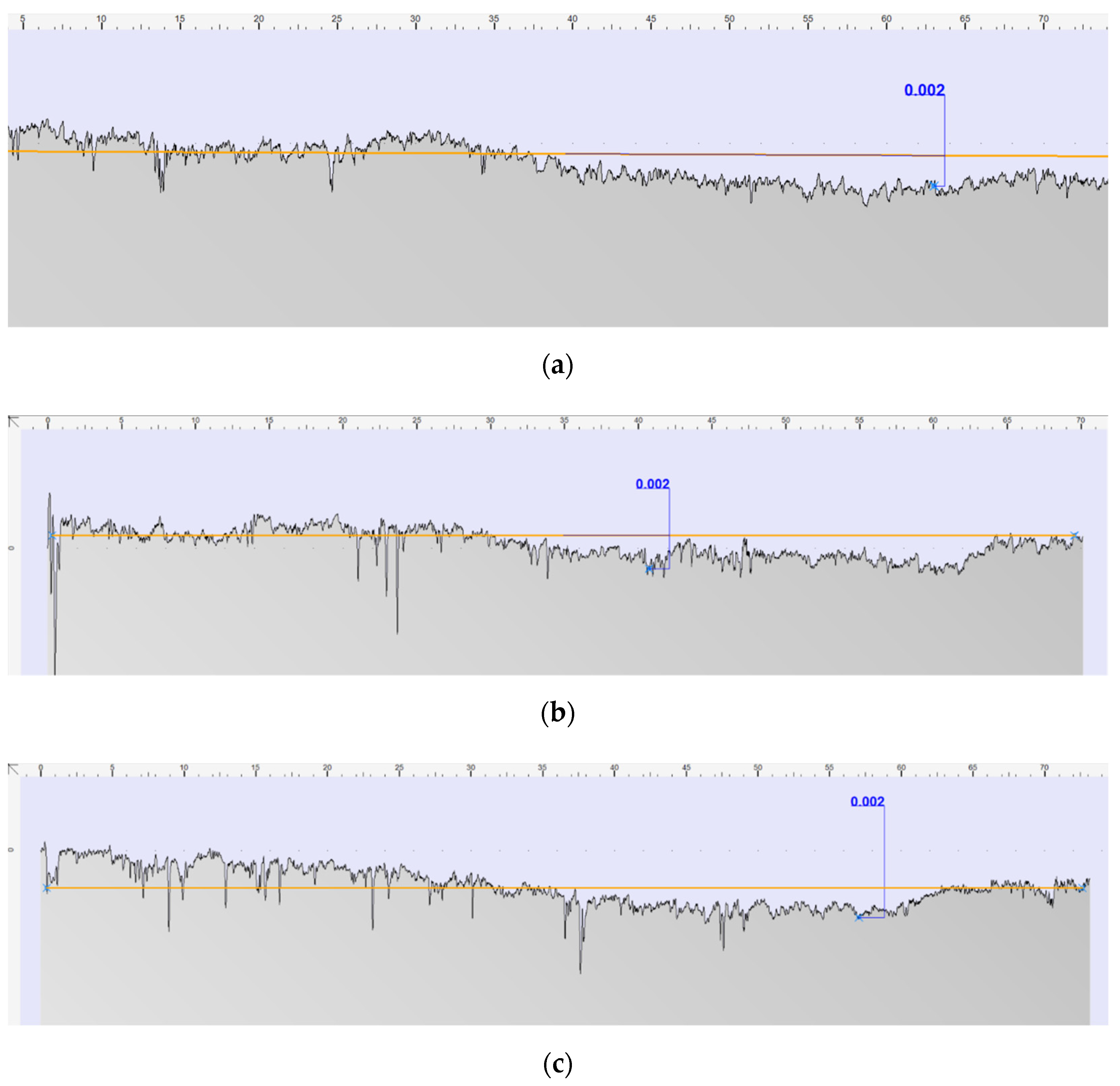
The flatness of the fixed basement, rotatory plate and translating counter pad was measured by a stylus profilometer of 1 μ m resolution. The paper reports some of the results related to the translating counter pad, since it exhibited the highest flatness errors. Figure 6 shows a scheme that illustrates the directions of the profile that are reported in Figure 7a–c.
Additionally, the geometry of the pressure intake was experimentally assessed through an electronic microscope to verify the presence of significant faults (see Figure 8).

2.3. Pressure Profile Measurements

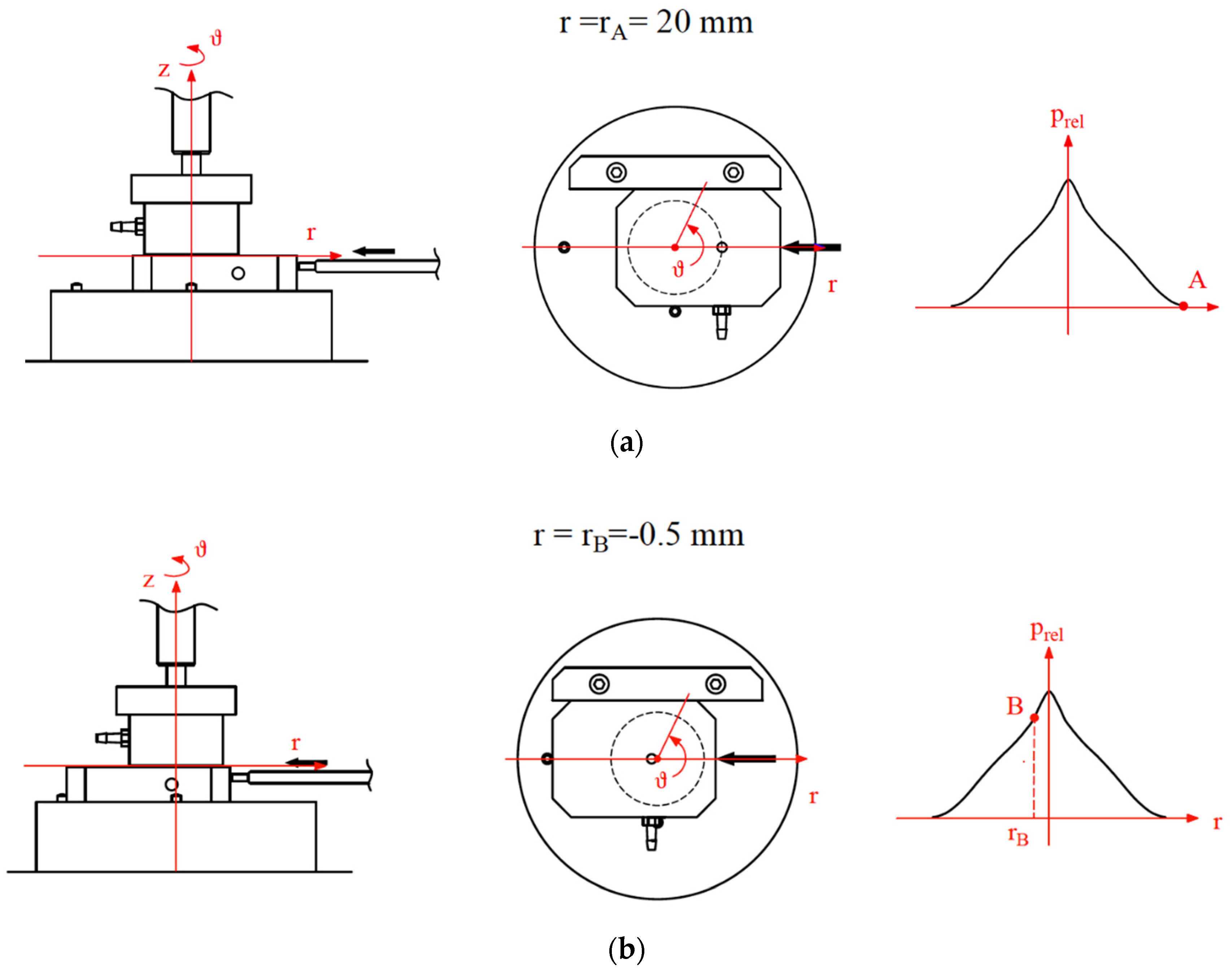
The pressure profiles of the pad were measured in the presence of different relative supply pressures ( p s r e l = 0.41, 0.51 and 0.61 MPa) and external loads. The external load rather than the air gap height was imposed, since it was found that this approach is more reliable when tests have to be repeated. Due to the axisymmetric geometry of the pad, pressure profiles were measured only in the radial direction r at θ   = 0°, for radial coordinates ranging from r B   = −0.5 to r A   = 20 mm. The points acquired at negative radii were acquired to better identify the position of the center of the supply hole of the pad and suitably compensate for accidental offsets of the micrometer. The density of the acquired point was gradually increased moving from the edge of the pad to its center. Figure 9a,b show schemes related to this kind of test by illustrating the initial ( r A ) and the final ( r B ) positions of the pressure intake. After the pad was supplied, the pressure intake was placed at the initial position r A where the desired external load was imposed. Thereafter, the pressure intake was moved from the initial position A to the final position B where the test ended. For each point of measure, the correspondent radial coordinate r e x p ,   i , pressure p e x p ,   i , air flow G e x p ,   i , air gap height h e x p ,   i and load capacity F e x p ,   i were acquired.

2.4. Static Characterization Procedure

The load capacity and air consumption curves of the pad were measured to verify the reliability of the data related to the air gap pressure profiles. The procedure adopted for the static characterization of the pad was the same as adopted in [18]. After the pad was supplied and placed on the counterpad. It is worth noting that the pressure intake has to be positioned outside the air gap otherwise it can affect the test results. a minimum value of the external load was imposed through the nut-screw system to keep the pad in a stable position. Subsequently, the external load was gradually increased till a null air flow was measured. Thereafter, the pressure source of the pad was shut down and the external load was gradually reduced to its initial value. During the execution of the test the values of the flow rates, force and pad displacement were simultaneously acquired via a data acquisition system. After the end of the test, the air gap heights were evaluated for each value of the measured force by subtracting the values of displacements measured in the presence and absence of supply air.

2.5. Identification of the Discharge Coefficients

The proposed identification procedure is a hybrid method simultaneously exploiting the experimental data related to the measured pressure profile in the viscous region and the analytical equations for circular and centrally fed aerostatic pads. Figure 10 shows one of the experimental pressure profiles measured through the procedure described in Section 2.3.
Here, as discussed in Section 1, it is possible to theoretically define the feed, entrance and viscous regions [3]. The proposed method is based on two main aspects:
  • It is well known that, in aerostatic bearings, the viscous region is by far the largest of the three regions.
  • It has been proven numerous times that isothermal and laminar flow models provide accurate predictions in the viscous region [19].
On the basis of these two aspects, the authors’ insight was to combine the measured experimental data with the analytical expression obtained for circular and centrally fed aerostatic bearings considering a laminar and isothermal fluid flow. The equations that are used in the proposed procedure are reported below (for further details on these equations readers can refer to Appendix A):
G g a p = π h 3 ( p 0 2 p a 2 ) 12 μ R g T s · l n ( R R 0 )
F = p 0 π R 0 2 π A 8 e 2 A [ e r f ( 2 A ) e r f ( 2 A · p a p 0 ) ]
A = ( 1 p a 2 p 0 2 ) l n ( R R 0 )
p ( r ) = p 0 1 ( 1 p a 2 p 0 2 ) l n ( r R 0 ) l n ( R R 0 )
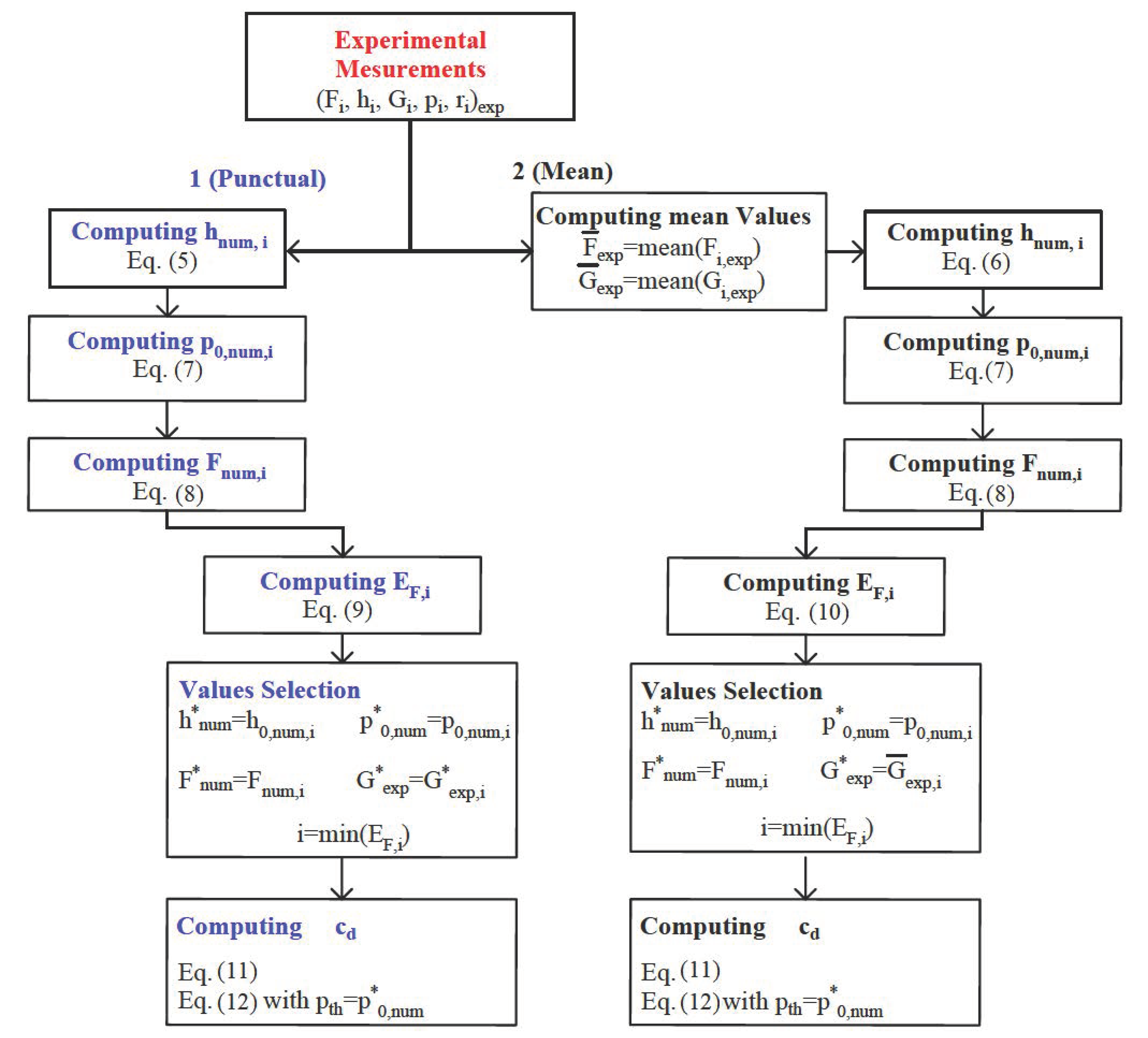
where, R g and μ are the gas constant and dynamic viscosity of the air. R , R 0 and p 0 are the pad and orifice radius and the pressure at the orifice edge. T s is the supply temperature of the gas, p a is the ambient pressure. F and G g a p are the load capacity and the air flow passing through the air gap. Two slightly different versions of the procedure are presented. These two versions will be termed analytical method 1 (punctual) and analytical method 2 (mean). For the sake of simplicity, the analytical method 1 will be taken as the reference method by underlining the difference with respect to the analytical method 2.
In the analytical method 1, Equation (5) is used to compute the actual air gap heights h 1 n u m , i by considering the measured air mass flow rates G e x p , i and a pressure values p e x p ,   i measured at the radii r e x p ,   i , where, the subscript i is an index refers to a specific measurement related to the pressure profile in the viscous region ( r e x p ,   i , p e x p ,   i , G e x p ,   i , F e x p ,   i ). Meanwhile, the analytical method 2 uses Equation (6):
h 1 n u m ,   i = 12 μ R g T s · l n ( R r e x p ,   i ) G e x p , i π ( p e x p ,   i 2 p a 2 ) 3
h 2 n u m ,   i = 12 μ R g T s · l n ( R r e x p ,   i ) G ¯ e x p π ( p e x p ,   i 2 p a 2 ) 3
where, G ¯ e x p is the mean air mass flow rate measured at the points belonging to the considered viscous region:
G ¯ e x p = 1 n   i = 1 n G e x p , i
It is worth pointing out that, in this instance, the experimental values considered in this procedure were taken at r > 3 mm. This choice was due to the evidence that the measurement performed at r 3 mm were probably influenced by the interaction between the pressure intake and the pad orifice [19]. Thereafter, in both the methods, Equation (7) is exploited to compute the pressure values at the edge of the pad orifice p 0 ,   n u m ,   i on the basis of the experimental pressures p e x p ,   i measured at the correspondent radii r e x p ,   i :
p e x p , i ( r e x p ,   i ) p 0 ,   n u m ,   i 1 ( 1 p a 2 p 0 ,   n u m ,   i 2 ) l n ( r e x p ,   i R 0 ) l n ( R R 0 ) = 0
This nonlinear equation was solved through the Regula Falsi method. Once the air gap heights h n u m , i and p 0 ,   n u m ,   i were computed for each experimental point i (in both methods), p 0 ,   n u m ,   i is used to compute the related numerical load capacities F n u m , i :
F n u m , i = p 0 ,   n u m ,   i π R 0 2 π A 8 e 2 A [ e r f ( 2 A ) e r f ( 2 A · p a p 0 ,   n u m ,   i ) ]
Finally, the values of p 0 ,   n u m ,   i , h n u m , i , F n u m , i and G e x p , i used to identify the discharge coefficients of the orifice are those that provide the minimum error on the computed load capacity: E 1 F , i for the method 1 (Equation (9)) and E 2 F , i for the method 2 (Equation (10)).
E 1 F , i = F n u m , i F e x p , i F e x p , i · 100
E 2 F , i = F n u m , i F ¯ e x p F ¯ e x p · 100
where, F ¯ e x p is the mean load capacity measured at the points belonging to the considered viscous region:
F ¯ e x p = 1 n   i = 1 n F e x p , i
At this point, the values that provide the minimum error on the load capacity ( p 0 ,   n u m , h n u m , F n u m and G e x p ) are used to compute the discharge coefficients of the pad orifice on the basis of its definition:
c d = G e x p G t h
where, G t h is the air flow computed considering and isentropic expansion from the internal chamber of the pad (whose pressure is p s ) to the gap entrance (whose pressure is p t h   =   p 0 ,   n u m ):
G t h = A p s R g T s ( 2 k k 1 )     φ ( p t h p s ) φ = { [ ( p t h p s ) 2 k ( p t h p s ) k + 1 k ] 1 / 2 ,   |   ( p t h p s ) > ( 2 k + 1 ) k k 1 = 0.5283 [ ( 2 k + 1 ) 2 k 1 ( 2 k + 1 ) k + 1 k 1 ] 1 / 2 ,   |   ( p t h p s ) ( 2 k + 1 ) k k 1 = 0.5283
where, p s is the supply pressure of the pad, k is the ratio of the specific heats of the gas and A is the cross-section area. This area can be conventionally chosen as equal to the orifice cross section π R 0 2 or as equal to the annular area at the air gap entrance 2 π R 0 h . In the latter case, since the cross-section area is a linear function of the air gap, the orifice is defined as inherently compensated. Conversely, in the former case, the orifice is defined as orifice compensated because the cross-section area does not depend on the air gap height. From a theoretical point of view, the inherent or the orifice compensated formulation should be chosen depending on the actual value of the air gap height:
h < R 0 / 2     Inherent   compensation h > R 0 / 2     Orifice   compensation
However, these two formulations are equivalent if they are integrated with suitably defined discharge coefficients. It is worth pointing out that the values of these discharge coefficients depend on the radial position where the theoretical downstream pressure is measured or computed. According to the Literature, this radial position is taken at the radius of the pad orifice or at the radius of the pressure crest downstream to the pad orifice ( c d a in the case of inherently compensation and c d c for the orifice compensation) [9,10,16]. In view of this, the proposed procedure was used to identify the discharge coefficients related to both the aforementioned formulations. According to [16], the identified c d a were reported as a function of the Reynolds number R e a = G 2 π μ R 0 whereas, c d c were reported as a function of the Reynolds number R e c = 2 G π μ R 0 and the ratio of the air gap height to the orifice diameter h / d . Figure 11 shows a flow chart that compares the main steps of the two methods.

3. Results

3.1. Discharge Coefficient Identification

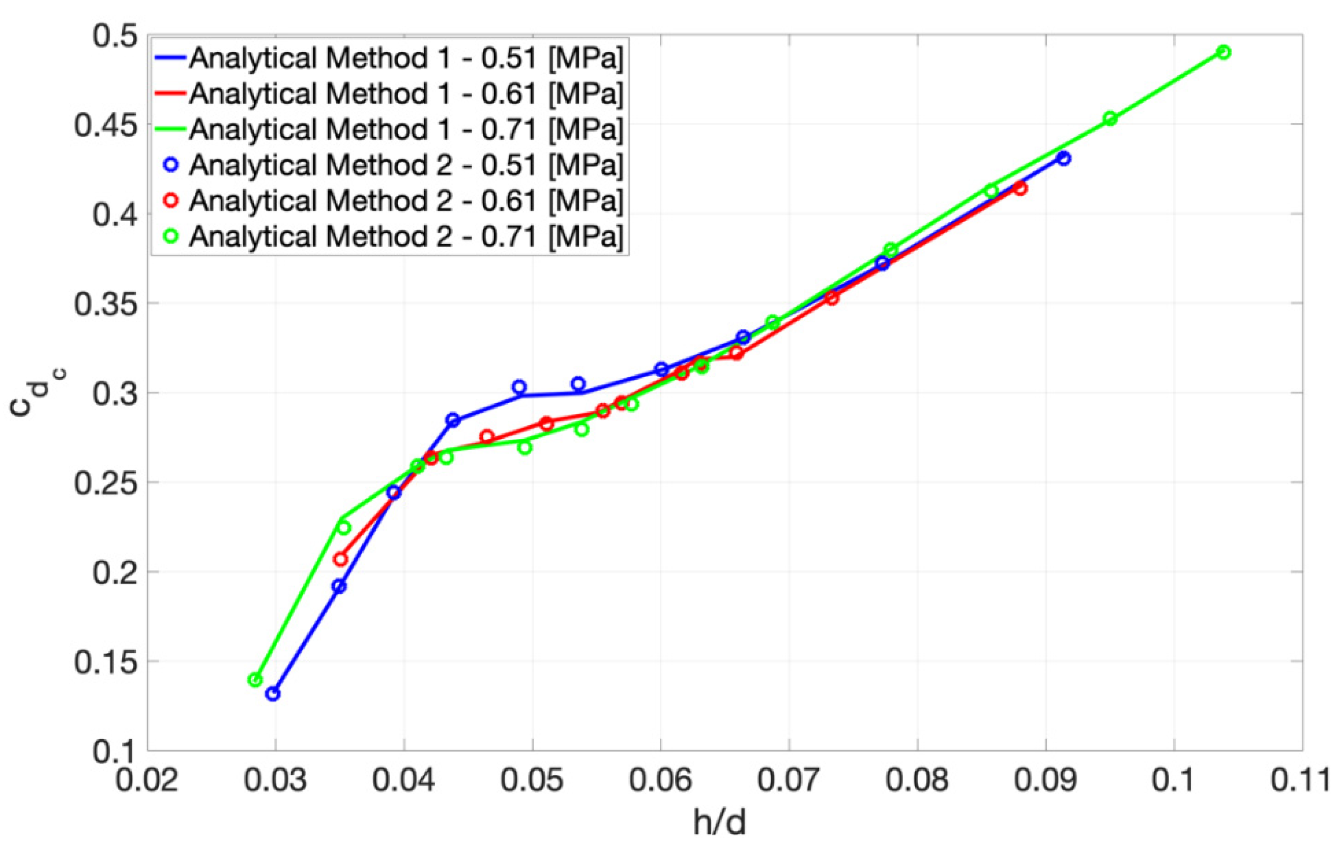
Figure 12 and Figure 13 report the results obtained through the two proposed identification methods. The results were obtained both for c d c and c d a . Figure 12 shows the trend of c d c expressed as a function of the ratio of the air gap height to the orifice diameter h / d at different relative supply pressures: p s r e l   = 0.41, 0.51 and 0.61 MPa.
As can be seen, the data scattering is very low. Starting from the lower Reynolds number three different slopes can be identified. According to this, it is reasonable to state that each slope may correspond to different flow regimes: laminar, transitional and turbulent. Moreover, it appears that c d c does not depend on the supply pressure.
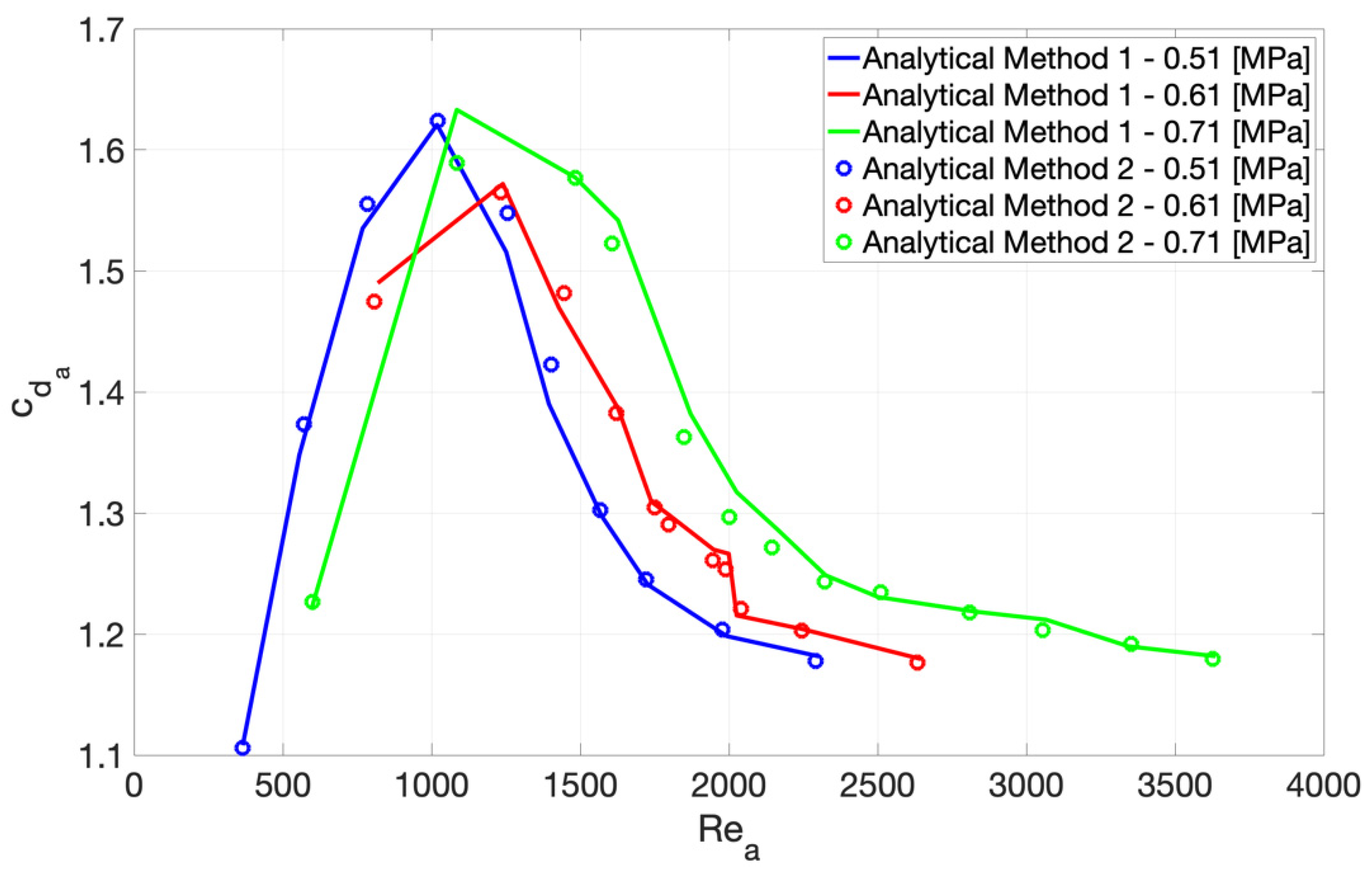
Figure 13 shows the trend of c d a expressed as a function of the correspondent Reynolds number R e a at different relative supply pressures: p s r e l   = 0.41, 0.51 and 0.61 MPa. Accordingly to the results obtained in [15], c d a , firstly, increases with the Reynolds number, reaches a maximum value and finally tends to the unit value. As for c d c , also the trend of c d a is slightly influenced by the supply pressure, since as the supply pressure is increased, the curves gradually move to the right.

3.2. Comparison with Static Characterisation Results

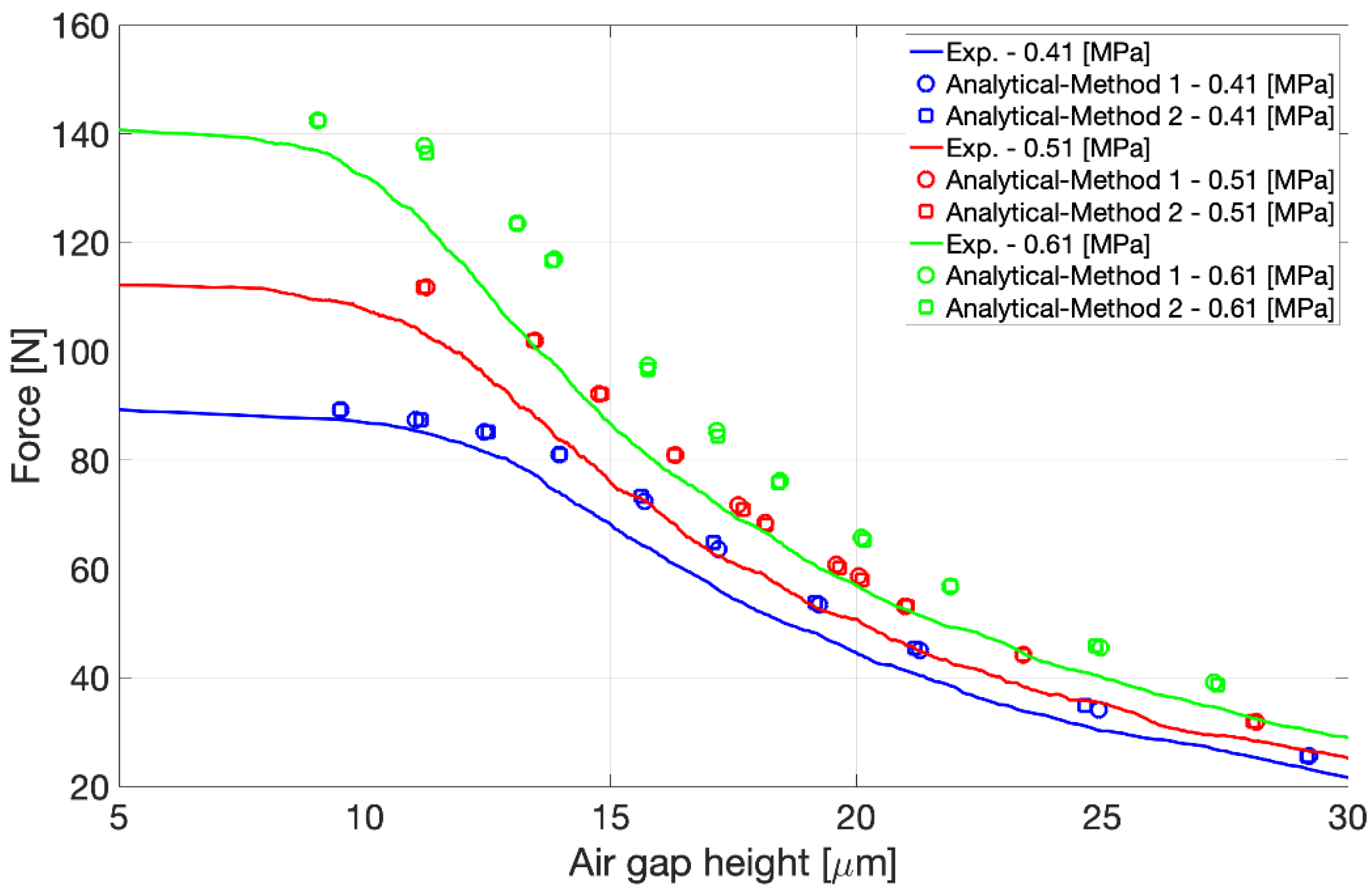
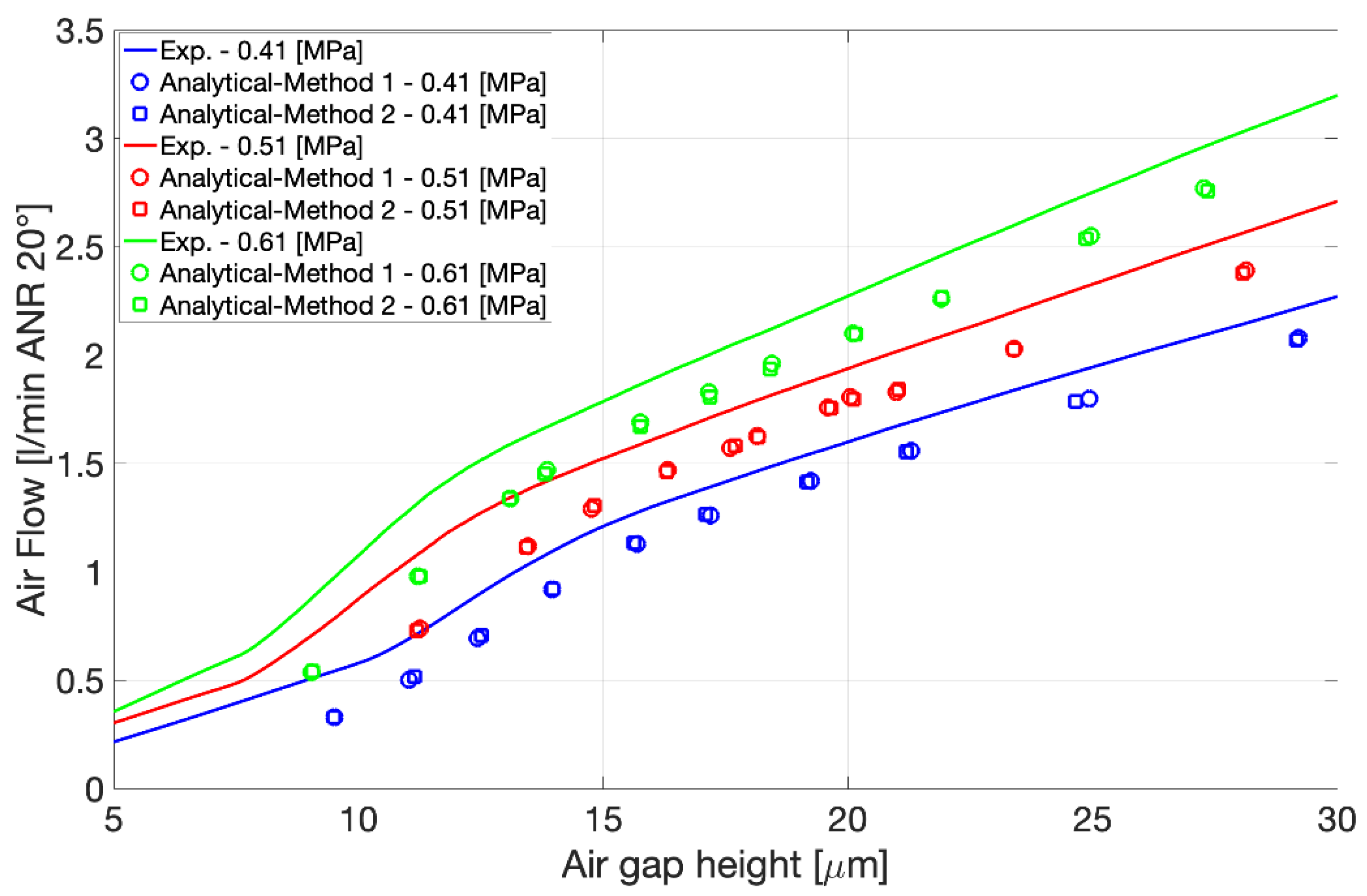
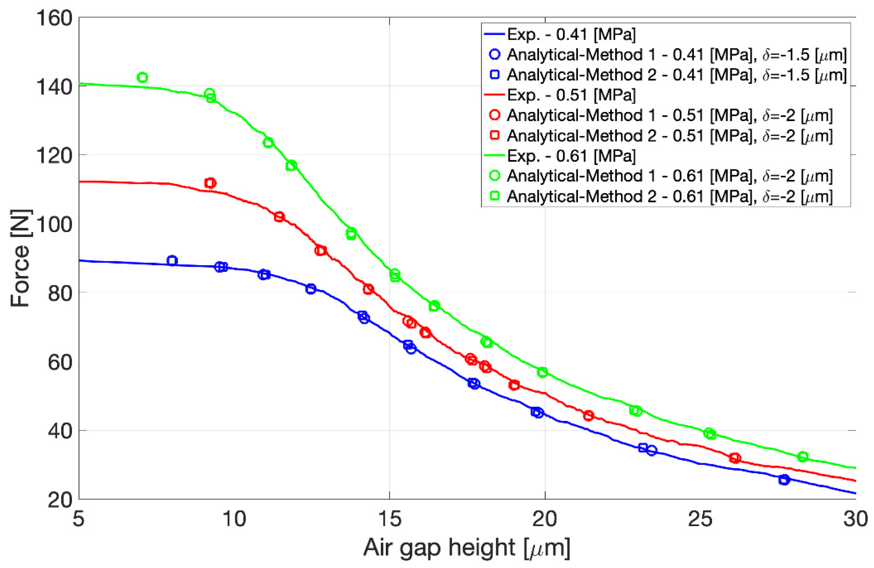
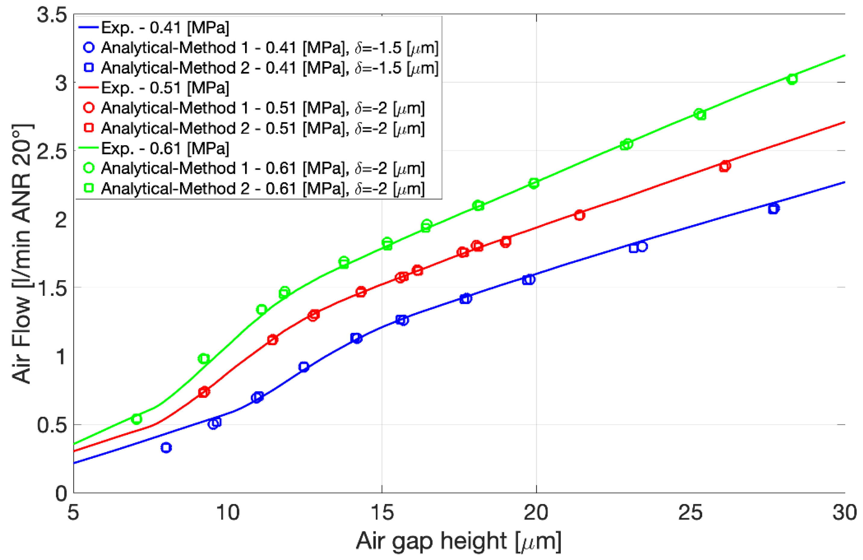
Figure 14 and Figure 15 compare the load capacity and the air consumption of the pad with the data obtained by the Analytical method 1 (punctual) and 2 (mean). Moreover, to exclude the influence of relative vertical displacements of the counter pad and/or the rotatory plate on the static characterization results, the curves reported in the following figures have been obtained as the mean of 5 different tests and they were verified on the test bench used in [18] using the same instruments, i.e., load cell, flowmeter and capacitive sensors.
As can be seen, the analytical results are in very good agreement regarding the force and the air consumption, but the values of the air gap height are overestimated. This overestimation may be attributed to different aspects relating to the flatness of the pad and the counter pad (see Section 2.1 and Section 2.2). In fact, as discussed in [20], the performance of pads with not perfectly flat surfaces can be studied by considering an equivalent gap. To verify this hypothesis, as in [20], the analytical curves obtained through the proposed identification methods were shifted by δ   =1.5 μ m (for p s = 0.41 MPa) and δ   = 2 μ m (for p s = 0.51 and 0.61 MPa). As appears in Figure 16 and Figure 17, the shifted curves match almost perfectly with the experimental ones.

4. Discussion and Conclusions

This paper proposed a hybrid approach to identify discharge coefficients of aerostatic bearing restrictors. The method was defined as hybrid since it exploits experimental data and the equations of an analytical model of a circular and centrally fed aerostatic pad. The authors believe that the use of this hybrid method may lead to several advantages with respect to the conventional experimental and numerical approaches that are reported in the Literature. Compared to the conventional experimental approaches that use the pressure crest downstream to the air gap entrance to compute discharge coefficients, the proposed method makes it possible to:
  • Reduce the data scattering thanks to the use of a mathematical framework (closed-form solution).
  • Overcome the difficulties related to the evaluation of the air gap height during the acquisition of the pressure profile.
  • Minimize the error on the numerical air flow and load capacity.
Moreover, differently to numerical models, the method makes it possible to consider equivalent air gap heights that allow the estimation of the deviation of the real bearing features (presenting their own geometry) to numerical or analytical models. The accuracy of the data obtained is confirmed by the fact that both the described methods provide similar results. However, it is worth pointing out that these methods require an accurate design of the adopted experimental apparatus and a careful choice of instrumentation, since these may affect the reliability of the obtained results.
In view of this, this methodology could be exploited to find semi-empirical expressions of c d c and c d a that take into account physical, e.g., Reynolds and Mach number and geometrical parameters, e.g., length to diameter and gap to diameter ratios, and thus further increase the accuracy of aerostatic bearing models.

Author Contributions

The work has been evenly divided between the authors, L.L., F.C., T.R., A.T., V.V. All authors have read and agreed to the published version of the manuscript.

Funding

This research received no external funding.

Conflicts of Interest

Authors declare no conflict of interest.

Appendix A

Equations (1)–(3) can be derived by considering the equilibrium of an infinitesimal fluid element belonging to the air gap under the flowing hypothesis:
  • isothermal laminar and isoviscous flow
  • negligible body forces
  • negligible velocity gradients along r and ϑ
  • Newtonian fluid
  • constant pressure along the z and ϑ direction p = p ( r ) (Due to the axisymmetry of the problem and the small thickness of the air gap.)
  • stationary conditions
Under these hypotheses, the equilibrium equation can be written as:
p r = μ 2 u z 2
By considering no slip conditions u ( 0 ) = u ( h ) = 0 at the bearing walls, the integration of Equation (A1), makes it possible to obtain the analytical expression of the air gap velocity profile
u ( z ) = z 2 2 μ p r z h 2 μ p r
From Equation (A2), the expression of the air mass flow rate G g a p can be compute as
G g a p = 2 π r o h ρ u ( z )   d z = 2 π p R T o h u ( z )   d z = π r p h 3 6 μ R g T p r
where, g = o h ρ u ( z )   d z is the air mass flow rate per unit width. Since G g a p is constant (see Equation (A7), this differential equation can be solved by the method of separation variable, by integrating over the air gap:
p 0 p a p p = 6 G g a p μ R g T π h 3 r 0 R 1 r   r
Thus, achieving Equation (1):
G g a p = π h 3 ( p 0 2 p a 2 ) 12 μ R g T s · l n ( R R 0 )
The analytical expression of the pressure distribution showed in Equation (4) can be obtained by considering the continuity equation applied at an infinitesimal fluid particle of the air gap, under stationary conditions:
r ( g r ) = r ( p h 3 r 12   μ R g T   p r ) = 0
which, integrated with respect to r , becomes:
p h 3 r 12   μ R g T   p r = C
where, C is a constant of integration. By integrating Equation (A7) over the radial extension of the air gap:
p 0 p a p h 3 12   μ R g T   p = r 0 R C r   r C = h 3 ( p a 2 p 0 2 ) 24 μ R g T
Once known the integration constant, it is possible to achieve the analytical expression of the air gap pressure distribution by substituting Equation (A8) in Equation (A7) and integrating from the air gap inlet to a generic cross section at the radius r ¯ where the pressure is equal to p ( r ¯ ) = p ¯
p 0 p ¯ p   p = ( p a 2 p 0 2 ) 2 r 0 r ¯ 1 r   r p ¯ = p ( r ¯ ) = p 0 { 1 l n ( r ¯ R 0 ) l n ( R R 0 ) [ 1 ( p a p 0 ) 2 ] } 1 2
Once the computed the expression of the air gap pressure distribution, the load capacity of the bearing can be written considering the equilibrium equation of the pad:
F P + π R 2 p a = π R 0 2 P 0 + 0 2   π r 0 R p ( r ) r   d r d ϑ
F P = π R 0 2 P 0 π R 2 p a + 0 2   π r 0 R p 0 { 1 l n ( r R 0 ) l n ( R R 0 ) [ 1 ( p a p 0 ) 2 ] } 1 2 r   d r d ϑ l
where, in Equation (A10), the terms on the left side correspond to the sum of the applied load and the force due to the ambient pressure whereas, on the right side there is the reacting force due to the air gap pressure distribution. To achieve the final expression of Equation (2), it is necessary to solve the integral l on the left side.
l = R 0 R r ( 1 l n ( r R 0 ) l n ( R R 0 ) l n ( r R 0 ) ) 1 2   d r
This can be done by adopting appropriate changes of variables. The first one is the following:
t = ( 1 A · l n ( r R 0 ) ) 1 2
where, A is equal to l n ( r R 0 ) l n ( R R 0 ) . At this stage, the integral l becomes:
l = R 0 2 2 1 p a p 0 4 t A e 2 ( 1 t 2 ) A · t d t
That can be solved integrating by parts:
l = R 0 2 2 { [ p a p 0 e 2 l n ( R R 0 ) 1 ] e 2 A 1 p a p 0 e 2 t 2 A d t }
By means of the change of variables of Equation (A16) and making use of the definition Equation (A17):
t = A 2 x
e r f ( y 1 ) e r f ( y 2 ) = 2 π y 2 y 1 e x 2 d x
it is possible to obtain:
l = R 0 2 2 { [ p a p 0 e 2 l o g ( R R 0 ) 1 ] π A 8 e 2 A [ e r f ( 2 A · p a p 0 ) e r f ( 2 A ) ] }
Equation (2) can be achieved by substituting the expression Equation (A18) in Equation (A11) and performing some algebraic steps, as follows:
F P = p 0 π [ R 0 2 R 2 p a p 0 + R 0 2 { [ p a p 0 e 2 l n ( R R 0 ) 1 ] π A 8 e 2 A [ e r f ( 2 A · p a p 0 ) e r f ( 2 A ) ] } ] F P = π R 2 p a + ( R R 0 ) 2 π p a R 0 2 p 0 π R 0 2 π A 8 e 2 A [ e r f ( 2 A · p a p 0 ) e r f ( 2 A ) ] F P = p 0 π R 0 2 π A 8 e 2 A [ e r f ( 2 A · p a p 0 ) e r f ( 2 A ) ] F = p 0 π R 0 2 π A 8 e 2 A [ e r f ( 2 A ) e r f ( 2 A · p a p 0 ) ]

References

  1. Lentini, L.; Moradi, M.; Colombo, F. A Historical Review of Gas Lubrication: From Reynolds to Active Compensations. Tribol. Ind. 2018, 40, 165–182. [Google Scholar] [CrossRef] [Green Version]
  2. Gao, Q.; Chen, W.; Lu, L.; Huo, D.; Cheng, K. Aerostatic bearings design and analysis with the application to precision engineering: State-of-the-art and future perspectives. Tribol. Int. 2019, 135, 1–17. [Google Scholar] [CrossRef]
  3. Waumans, T.; Al-Bender, F.; Reynaerts, D. A semi-analytical method for the solution of entrance flow effects in inherently restricted aerostatic bearings. In Turbo Expo: Power for Land, Sea, and Air; ASME: Berlin, Germany, 2008; Volume 43154, pp. 1047–1057. [Google Scholar]
  4. Mori, H.; Miyamatsu, Y. Theoretical flow-models for externally pressurized gas bearings. J. Lubr. Technol. 1969, 91, 181–193. [Google Scholar] [CrossRef]
  5. Gao, S.; Cheng, K.; Chen, S.; Ding, H.; Fu, H. CFD based investigation on influence of orifice chamber shapes for the design of aerostatic thrust bearings at ultra-high speed spindles. Tribol. Int. 2015, 92, 211–221. [Google Scholar] [CrossRef]
  6. Zhang, J.; Zou, D.; Ta, N.; Rao, Z. Numerical research of pressure depression in aerostatic thrust bearing with inherent orifice. Tribol. Int. 2018, 123, 385–396. [Google Scholar] [CrossRef]
  7. Helene, M.; Arghir, M.; Frene, J. Numerical three-dimensional pressure patterns in a recess of a turbulent and compressible hybrid journal bearing. J. Trib. 2003, 125, 301–308. [Google Scholar] [CrossRef]
  8. Mori, H. A theoretical investigation of pressure depression in externally pressurized gas-lubricated circular thrust bearings. J. Basic Eng. 1961, 83, 201–208. [Google Scholar] [CrossRef]
  9. Chang, S.H.; Chan, C.W.; Jeng, Y.R. Numerical analysis of discharge coefficients in aerostatic bearings with orifice-type restrictors. Tribol. Int. 2015, 90, 157–163. [Google Scholar] [CrossRef]
  10. Chang, S.H.; Chan, C.W.; Jeng, Y.-R. Discharge coefficients in aerostatic bearings with inherent orifice-type restrictors. J. Tribol. 2015, 137. [Google Scholar] [CrossRef]
  11. Miyatake, M.; Yoshimoto, S. Numerical investigation of static and dynamic characteristics of aerostatic thrust bearings with small feed holes. Tribol. Int. 2010, 43, 1353–1359. [Google Scholar] [CrossRef]
  12. Nishio, U.; Somaya, K.; Yoshimoto, S. Numerical calculation and experimental verification of static and dynamic characteristics of aerostatic thrust bearings with small feedholes. Tribol. Int. 2011, 44, 1790–1795. [Google Scholar] [CrossRef]
  13. Renn, J.-C.; Hsiao, C.-H. Experimental and CFD study on the mass flow-rate characteristic of gas through orifice-type restrictor in aerostatic bearings. Tribol. Int. 2004, 37, 309–315. [Google Scholar] [CrossRef]
  14. Al-Bender, F.; Van Brussel, H. A method of “separation of variables” for the solution of laminar boundary-layer equations of narrow-channel flows. J. Tribol. 1992. [Google Scholar] [CrossRef]
  15. Zhang, J.; Zou, D.; Ta, N.; Rao, Z.; Ding, B. A numerical method for solution of the discharge coefficients in externally pressurized gas bearings with inherent orifice restrictors. Tribol. Int. 2018, 125, 156–168. [Google Scholar] [CrossRef]
  16. Belforte, G.; Raparelli, T.; Viktorov, V.; Trivella, A. Discharge coefficients of orifice-type restrictor for aerostatic bearings. Tribol. Int. 2007, 40, 512–521. [Google Scholar] [CrossRef]
  17. Belforte, G.; Colombo, F.; Raparelli, T.; Trivella, A.; Viktorov, V. A new identification method of the supply hole discharge coefficient of gas bearings. Tribol. Des. WIT Trans. Eng. Sci. 2010, 66, 95–105. [Google Scholar]
  18. Colombo, F.; Lentini, L.; Raparelli, T.; Trivella, A.; Viktorov, V. Dynamic Characterisation of Rectangular Aerostatic Pads with Multiple Inherent Orifices. Tribol. Lett. 2018, 66. [Google Scholar] [CrossRef]
  19. Belforte, G.; Raparelli, T.; Trivella, A.; Viktorov, V.; Visconte, C. CFD analysis of a simple orifice-type feeding system for aerostatic bearings. Tribol. Lett. 2015, 58, 25. [Google Scholar] [CrossRef] [Green Version]
  20. Colombo, F.; Lentini, L.; Raparelli, T.; Viktorov, V.; Trivella, A. On the Static Performance of Concave Aerostatic Pads. In IFToMM World Congress on Mechanism and Machine Science; Springer: Cham, Switzerland, 2019; pp. 3919–3928. [Google Scholar]
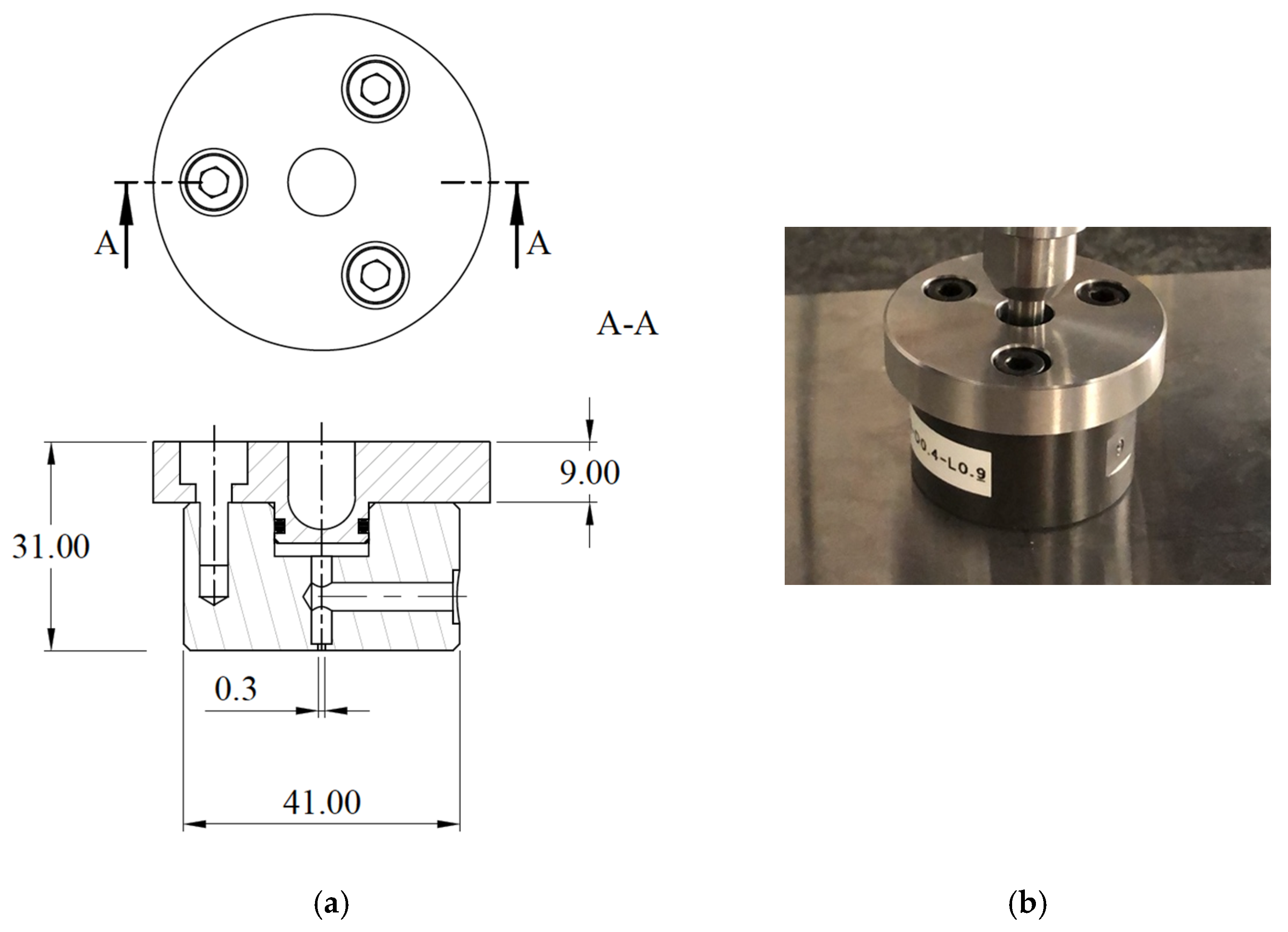
Figure 1. (a) Pad cross-section. (b) Pad photograph.
Lubricants 09 00055 g001
Figure 2. (a) Measured orifice diameter. (b) Measured diameter of the outer edge of the chamfer.
Lubricants 09 00055 g002
Figure 3. Measurement of the pad profile.
Lubricants 09 00055 g003
Figure 4. (a) First measurement of the pad profile (mm). (b) Second measurement of the pad profile (mm).
Lubricants 09 00055 g004
Figure 5. Scheme of test bench used to measure the static characteristics and the air gap pressure profiles of the pad.
Lubricants 09 00055 g005
Figure 6. Directions of the counter pad profiles reported in Figure 7a,b.
Lubricants 09 00055 g006
Figure 7. (a) Counterpad profile measured along the direction 1 (mm). (b) Counterpad profile measured along the direction 2 (mm). (c) Counterpad profile measured along the direction 3 (mm).
Lubricants 09 00055 g007
Figure 8. Geometry of the pressure intake.
Lubricants 09 00055 g008
Figure 9. (a) Initial position of the pressure intake ( r A ). (b) Final position of the pressure intake ( r B ).
Lubricants 09 00055 g009
Figure 10. Example of measured pressure profile ( p s r e l   = 0.61 MPa, F ¯ e x p   = 30 N).
Lubricants 09 00055 g010
Figure 11. Flow chart of the two proposed methods.
Lubricants 09 00055 g011
Figure 12. Trend of c d c expressed as a function of the ratio of the air gap height to the orifice diameter h / d at different relative supply pressures: 0.41, 0.51 and 0.61 MPa.
Lubricants 09 00055 g012
Figure 13. Trend of c d a expressed as a function of the correspondent Reynolds number R e a at different relative supply pressures: 0.41, 0.51 and 0.61 MPa.
Lubricants 09 00055 g013
Figure 14. Comparison between the load capacity obtained through the static characterizations and the results from the proposed identification methods.
Lubricants 09 00055 g014
Figure 15. Comparison between the air consumption obtained through the static characterizations and the results from the proposed identification methods.
Lubricants 09 00055 g015
Figure 16. Comparison between the load capacity obtained through the static characterizations and the results from the proposed identification methods (shifted).
Lubricants 09 00055 g016
Figure 17. Comparison between the air consumption obtained through the static characterizations and the results from the proposed identification methods (shifted).
Lubricants 09 00055 g017
Publisher’s Note: MDPI stays neutral with regard to jurisdictional claims in published maps and institutional affiliations.