Article

Significance of Slippage and Electric Field in Mucociliary Transport of Biomagnetic Fluid

Department of Quantitative Methods, College of Business Administration, Imam Abdulrahman Bin Faisal University, Dammam 31441, Saudi Arabia
Lubricants 2021, 9(5), 48; https://doi.org/10.3390/lubricants9050048
Submission received: 22 March 2021 / Revised: 8 April 2021 / Accepted: 24 April 2021 / Published: 28 April 2021

Abstract

:
Shear stress at the cilia wall is considered as an imperative factor that affects the efficiency of cilia beatings as it describes the momentum transfer between the fluid and the cilia. We consider a visco-inelastic Prandtl fluid in a ciliated channel under electro-osmotic pumping and the slippage effect at cilia surface. Cilia beating is responsible for the stimulation of the flow in the channel. Evenly distributed cilia tend to move in a coordinated rhythm to mobilize propulsive metachronal waves along the channel surface by achieving elliptic trajectory movements in the flow direction. After using lubrication approximations, the governing equations are solved by the perturbation method. The pressure rise per metachronal wavelength is obtained by numerically integrating the expression. The effects of the physical parameters of interest on various flow quantities, such as velocity, pressure gradient, pressure rise, stream function, and shear stress at the ciliated wall, are discussed through graphs. The analysis reveals that the axial velocity is enhanced by escalating the Helmholtz–Smoluchowski velocity and the electro-osmosis effects near the elastic wall. The shear stress at the ciliated boundary elevates with an increase in the cilia length and the eccentricity of the cilia structure.

1. Introduction

Cilia-supported propulsions play an important part in many physiological and bioengineering systems. Cilia appear as protuberances on the outer surface of eukaryotic cells. These appendage organelles can produce a current in a fluid motion for the passage of fluid and substances through the cell’s surface. They tend to move as a group and generate a rhythmic wave effect by attaining power and recovery strokes. Motile cilia [1,2,3,4,5,6] are present in the respiratory system to make airways clear by removing mucus and dust; in the digestive system to propel food and its egestion; the lining of female fallopian tubes to support the movement of eggs and fertilization; and in male efferent ductules for mixing the sperm cells to keep them from accumulating and hindering the tube, so they can reach to their ultimate target. They also work for the transport of spinal fluid through the brain.
Primary cilia act as a sensory apparatus for the cell [7] and play a vital part in sensory neurons. They are found in the kidneys, eye retina, ears and brain. Due to its diverse applications in human life, it has become a fascinating area of research for many scientists. Brennen [8] studied the locomotion of a cell through a viscous fluid induced by a harmonic wave of progression on its surface. Qiu et al. [9] reported that to move several biological microorganisms, cilia and flagella perform reciprocal motions in a non-Newtonian fluid medium at a low Reynolds number. Eytan and Elad [10] presented a theoretical study of egg transport in the fallopian tube and ovum in the uterine cavity by using the intrauterine fluid motion that is primarily intended for myometrial contractions. Recently, Farooq et al. [11] studied the flow of non-Newtonian fluid in a symmetric channel. It is assumed that the flow is induced by metachronal waves of cilia that are present on the inner surface of the channel wall under long wavelength and small Reynolds number approximations. Farooq and Siddiqui [12] studied the transport of seminal fluid through the ductus efferent due to metachronal propulsions in couple-stress fluid. The involvement of cilia in the female fallopian tube and uterus is reported in recent studies [13,14].
The analysis of rheological fluids in electric and magnetic fields has become a mounting and interesting area for many researchers. Magnetofluid is always under special consideration in physiological and bioengineering disciplines. Stud et al. [15] examined the peristaltic motion of blood in the presence of a moving magnetic field applied in the normal direction of the fluid flow. They considered that the mean velocity distribution decreases by increasing the magnetic field. Mekheimer [16] addressed the peristaltic motion of magnetohydrodynamic (MHD) couple-stress fluid in a symmetric channel of non-uniform thickness. He observed that the pressure rise for MHD fluids are greater than the hydrodynamic fluids. Maqbool et al. [17] considered the MHD flow of Jeffery fluid due to metachronal waves. Hayat et al. [18] studied the significance of a magnetic field on the Carreau fluid motion in symmetric channel. The ciliary pumping flow of couple-stress fluid in the presence of an applied external magnetic field was examined by Ramesh et al. [19]. Some attempts analyzing the peristaltic flow through the perspective of MHD have been mentioned in other studies [20,21,22].
An electro-osmotic stream grows in response to the submission of electric field to the fluid under consideration. Applications include some advanced electronic apparatus in microfluidic and nanofluidic applications, such as electro-osmotic fluid pumps, liquid drug delivery, microelectronic chip cooling, DNA testing, lab-on-a-chip devices and microfabricated fluid devices etc. In this respect, the innovative attempt was presented by Burgreen and Nakache [23]. Yang and Li [24] considered the electric double-layer effect on pressure pumping flow through a rectangular microchannel and established that the electric double-layer at the liquid–solid interface has a tendency to deviate the flow features. Chaube et al. [25] examined the influence of the electric double-layer on micropolar fluid and highlighted the use of this model in lab-on-chip appliances and microperistaltic pumps. A mathematical study dealing with an inclined magnetic field applied to the peristaltic motion of Jeffrey fluid in the presence of an electric double-layer was conducted by Akram et al. [26]. Some recent investigations with the idea of combining electric and magnetic fields in peristaltic flows through microchannels are mentioned in [27,28,29,30].
The flows that produce large changes in velocity over short distances subject to a high shear rate induce a deceleration in fluid viscosity. Mucus is considered a non-Newtonian physiological fluid. Unlike Newtonian fluids, when it is rapidly sheared, a slippage plane develops between the mucus layers and hence decreases the mucus viscosity. If mucus keeps on the slip, the viscosity in the slippage surface remains small and makes the mucus a good lubrication. During a cough, because of high shear stress, the mucin fibers separate and untangle at the slippage surface [31,32].
The sperm cells of small rodents [33] are kept in highly viscoelastic mucus in the epidermis. At a high shear rate, the viscosity of mucus decreases dramatically. During ejaculation, the mucus near the wall bears high shear stress and consequently constructs a slippage plane between the storage bolus and the surface. Tripathi et al. [34] presented a theoretical model of the peristaltic motion of blood enclosure with partial slip effects under long wavelength and small Reynolds number. Makinde et al. [35] investigated the thermal analysis of Walters’ B fluid under the effects of a magnetic field and slip condition. Hayat et al. [36,37] presented the slip effects on peristalsis in an asymmetric channel. Some important studies reporting the significance of slip-on physiological flows are listed here for interested readers [38,39,40,41].
Given the above discussion, the aim of the present study is to investigate the effects of slippage on cilia-endorsed transport of visco-inelastic, pseudoplastic Prandtl fluid under a magnetic field in an electro-osmotic pump. The analysis is carried out in a wave frame. Governing equations are simplified under the long wavelength and small Reynolds number assumptions. Numerical integration is performed to find pressure rise ∆P per metachronal wavelength. Perturbation solutions of axial velocity u(y), pressure gradient dp/dx, shear stress τxy at the ciliated wall surface, and stream functions are obtained. Parametric study to different influential variables is also organized.

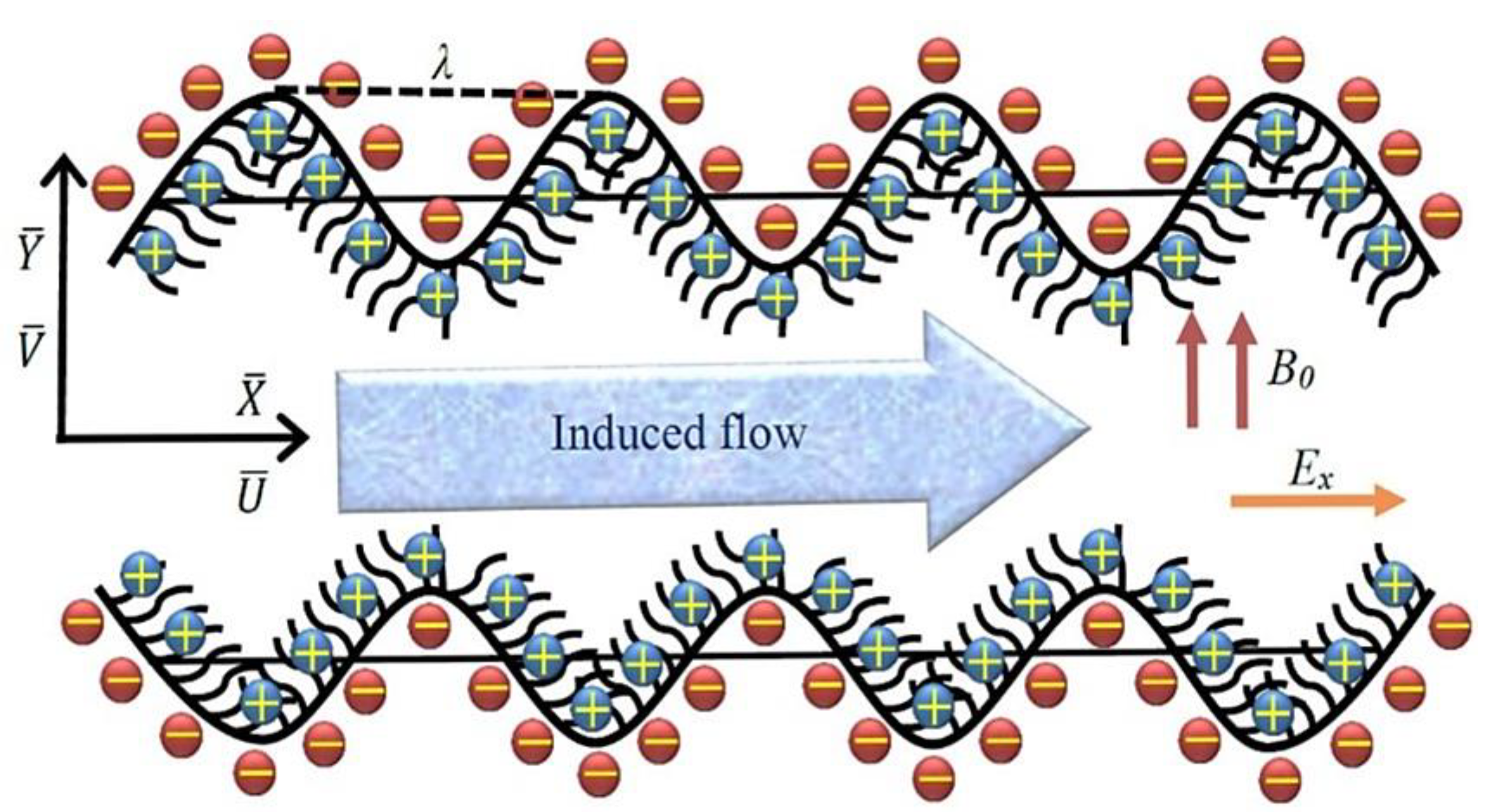
2. Mathematical Formulation

Consider two-dimensional pumping transport through a ciliated channel filled with incompressible non-Newtonian Prandtl fluid by incorporating the effects of electric E and uniform magnetic field B0. The flow is stimulated due to periodic beatings of cilia knocking with constant speed c, which synchronize their knocks to generate metachronal waves along the channel wall side. It is also intended that partial velocity slip is present at the ciliated boundary. Using a rectangular coordinate system, the X-axis is taken along the parallel direction of wave transmission, and the Y-axis is perpendicular to it (see Figure 1 for instance). The shape of wall surface lining cilia is described as [39,42]:
Y - = f ( X - , t ) = H = [ a + a ε cos ( 2 π λ ( X - c t ) ) ]
It is assumed that cilia tip the lash by attaining an elliptical motion configuration and are vertically located at:
X - = g ( X - , t ) = X 0 + a ε α sin ( 2 π λ ( X - c t ) )
where a, α, ε, H, t, λ, and X0 are mean channel width, eccentricity of an elliptic path, cilia length parameter, half channel width, time, wavelength and indicated position of the particle.
In a laboratory frame, the axial and transverse velocity components at the channel wall and governing equations of current flow problem are listed as:
U 0 ¯ = ( X ¯ t ) X 0 =   ( 2 π λ ) a c ε α cos ( 2 π λ ( X ¯ c t ) ) 1 ( 2 π λ ) a ε α cos ( 2 π λ ( X ¯ c t ) ) ,
V 0 ¯ = ( Y ¯ t ) X 0 = ( 2 π λ ) a c ε α sin ( 2 π λ ( X ¯ c t ) ) 1 ( 2 π λ ) a ε α sin ( 2 π λ ( X ¯ c t ) ) ,
U ¯ X ¯ + V ¯ Y ¯ = 0 ,
ρ ( t + U ¯ X ¯ + V ¯ Y ¯ ) U ¯ = P ¯ X ¯ + S ¯ X ¯ X ¯ X ¯ + S ¯ X ¯ Y ¯ Y ¯ σ B 0 2 U ¯ + ρ e E x ,
ρ ( t + U ¯ X ¯ + V ¯ Y ¯ ) V ¯ = P ¯ Y ¯ + S ¯ X ¯ Y ¯ X ¯ + S ¯ Y ¯ Y ¯ Y ¯ σ B 0 2 V ,
where, ρ is the fluid density, B0 the constant magnetic, σ the electrical conductivity, p the pressure and ( U ¯ , V ¯ ) are the velocity components in ( X ¯ , Y ¯ ) direction.
The electric potential existing on a ciliated wall is described with the Poisson–Boltzmann equation as:
2 Φ ¯ = ρ e ϵ ϵ ο ,
here Φ ¯ , ρe and ϵ, ϵ0 correspond to the electroosmotic potential function, net charge density, permittivity of medium and permittivity of free space. For dual fluid owning two types of ionic charges (equal and opposite), the net charge density is calculated as:
ρ e = e z ( n ¯ + n ¯ ) ,
with n ¯ + ,   n ¯ are positive and negative charge in concentration, e is the electric charge and z is the valence of ions.
We suppose that wall zeta potential (≤25 mV) is adequately small and therefore the Debyeh-Huckel linearization applies as:
ρ e = 2 n ο z e sinh ( z e Φ ¯ k b T a v e ) ,
where kb, Tave and no are the Boltzmann constant, local average temperature, and the average amount of electrolytes. When the electrical potential is lower than temperature field, the Debyeh–Huckel approximation applies as:
sinh ( z e Φ ¯ k b T a v e ) z e Φ ¯ k b T a v e
Employing Equations (9)–(11) in Equation (8), the potential function for the electric double-layer is represented by:
2 Φ ¯ = 2 n ο z 2 e 2 Φ ¯ k b T a v e ϵ ϵ ο .
The relative coordinates, velocity components and pressure are converted from the laboratory frame to wave frame of reference by defining the transformations as:
x ¯ = X ¯ c t ,   y ¯ = Y ¯ ,   u ¯ = U ¯ c ,   v ¯ = V ¯ ,   p ¯ ( x , y ) = P ¯ ( X ¯ , Y ¯ , t ) .
The extra stress for the Prandtl fluid is defined as [43,44]:
S ¯ = S ¯ X Y = [ A μ s i n 1 [ 1 C { ( U ¯ Y ¯ ) 2 ( V ¯ X ¯ ) 2 } 1 / 2 ]   { ( U ¯ Y ¯ ) 2 ( V ¯ X ¯ ) 2 } 1 / 2 ] U ¯ Y ¯   ,
in which A and C are material constants of Prandtl fluid model. Moreover, the function sine inverse is expanded up to the first two terms only, since the rest of the terms are negligible.
Introducing non-dimensional quantities as:
x = x ˉ λ , y = y ˉ a , u = u ˉ c , v = λ v ˉ a c , β = a λ , H = H ˉ a , t = c t ˉ a , p = a 2 p ˉ μ c λ , Φ = Φ ˉ ζ ϕ = η c 2 c 2 a 2 , S = a μ c S ˉ , R e = a c v , ϕ = α c 2 c 2 a , η = μ A c , M = σ μ B 0 a , U h s = E x o ζ c μ f }
where (u, v) are velocity components in (x, y) direction, p is the fluid pressure, β is the wave number, Re is the Reynolds number, M is the Hartmann number, and ϕ the time relaxation parameter.
Using Equations (13)–(15) into Equations (6),(7) and (12) and then employing lubrication approximations, the resulting equations take the following form:
p x = y [ η ( u y ) + ϕ 6 ( u y ) 3 ] M 2 ( u + 1 ) + U h s 2 Φ y 2 ,
p y = 0 ,
2 Φ y 2 = K 2 Φ .
The corresponding boundary conditions of the flow problem are defined as:
u y = 0 ,       Φ y = 0   at   y = 0 ,
+ ξ [ η u y + ϕ 6 ( u y ) 3 ] = 1 2 π α ε β cos ( 2 π x ) 1 2 π α ε β cos ( 2 π x ) ,   Φ = 1   at   y = h = 1 + ε cos ( 2 π x )
where ξ (=L/a), h are a dimensionless form of slip parameter, ciliated wall and K = a z e 2 n ο ϵ ϵ ο k b T a v e is the electro-osmosis parameter exhibited as the ratio of the mean channel width to the Debye length.
The pressure rise per wavelength, dimensionless volume flow rate and mean flow rate are formulated as:
Δ P λ = 0 1 ( d p d x ) d x ,
F = 0 h u d y ,           Q = F + 1 .
The dimensionless shear rate is computed using a Taylor series expansion of Equation (14) and normalizing with dimensionless Equation (15) as
S X Y = η ( u y ) + ϕ 6 ( u y ) 3 .

3. Solution

To calculate the solutions of Equations (16) and (18) subject to the boundary conditions Equations (19) and (20), we apply perturbation procedure by selecting ϕ as perturbation parameter. We expand the flow quantities as:
u = u 0 + ϕ u 1 + O ( ϕ 2 ) ,
d p d x = d p 0 d x + ϕ d p 1 d x + O ( ϕ 2 ) ,
F = F 0 + ϕ F 1 + O ( ϕ 2 ) ,
Φ = Φ 0 + ϕ Φ 1 + O ( ϕ 2 ) ,
and get a zeroth-order and first-order system of equations.

3.1. Zeroth-Order System

d p 0 d x = η 2 u 0 y 2 M 2 ( u 0 + 1 ) + U h s 2 Φ 0 y 2
2 Φ 0 y 2 = K 2 Φ 0 ,
F 0 = 0 h u 0 d y ,
with boundary conditions as:
u 0 y = 0 ,       Φ 0 y = 0         y = 0 ,
u 0 + ξ η u 0 y = 1 2 π α ε β cos ( 2 π x ) 1 2 π α ε β cos ( 2 π x ) ,   Φ 0 = 1     at     y = h = 1 + ε cos ( 2 π x ) .

3.2. First-Order System

d p 1 d x = η 2 u 1 y 2 M 2 u 1 + ϕ 6 y ( u 0 y ) 3 + U h s 2 Φ 1 y 2 ,
2 Φ 1 y 2 = K 2 Φ 1 ,
F 1 = 0 h u 1 d y ,
with boundary conditions as:
u 1 y = 0 ,       Φ 1 y = 0     at     y = 0 ,  
u 1 + ξ [ η u 1 y + 1 6 ( u 0 y ) 3 ] = 0 ,   Φ 1 = 1   at   y = h = 1 + ε cos ( 2 π x ) .
We have calculated the solutions of the zeroth- and first-order system of equations with Mathematica software. The data for the pressure rise (per metachronal wavelength) is obtained by performing the numerical integration of Equation (21). To validate our approximate analytic solution, we provide a comparison by computing a numerical solution by a shooting method. Table 1 is produced by reporting the numerical values of velocity gradient at the wall of the channel. From the table a good agreement is seen between both solution methodologies. This provides a good check on the validity of the present analytic solution.

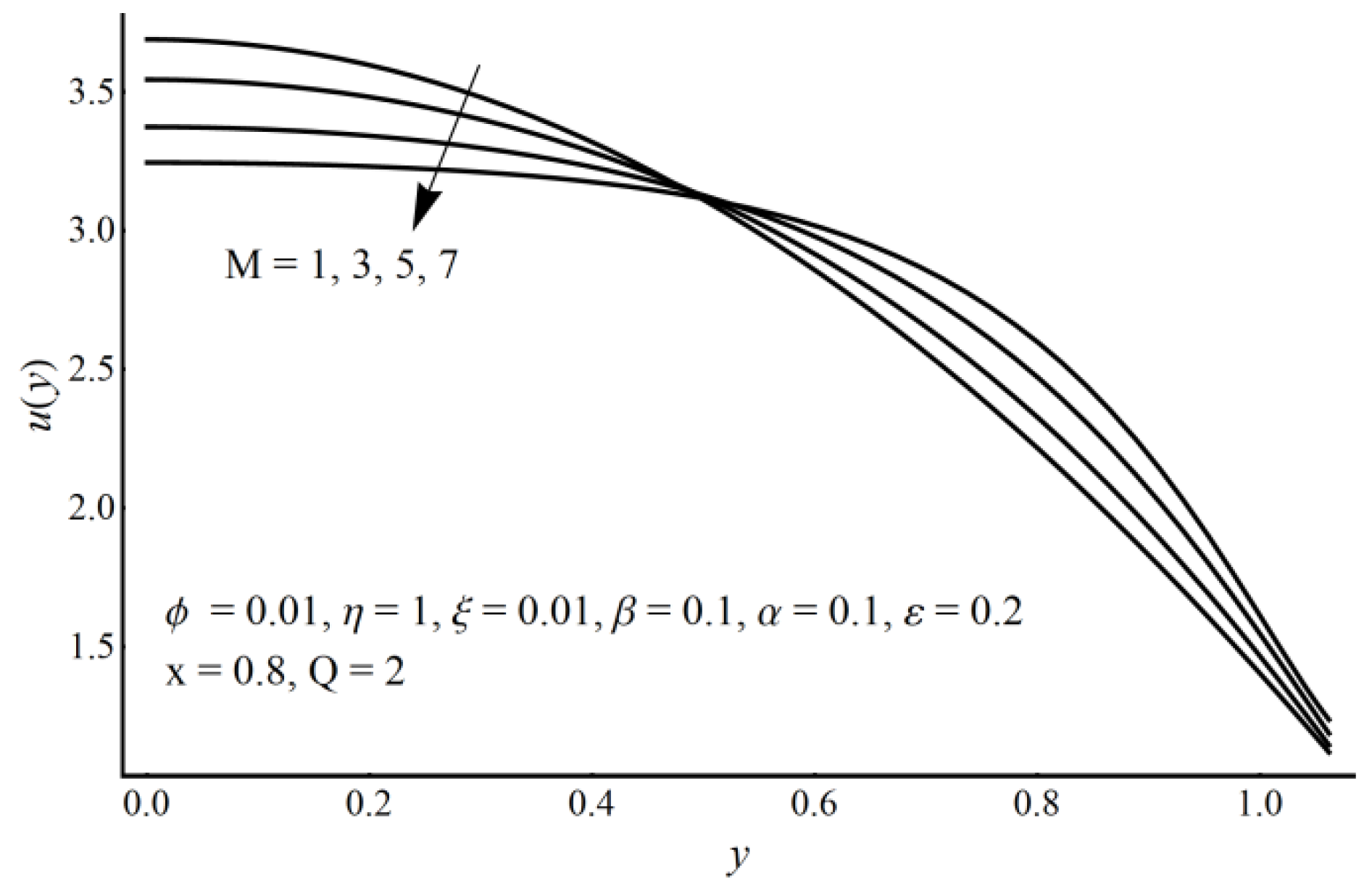
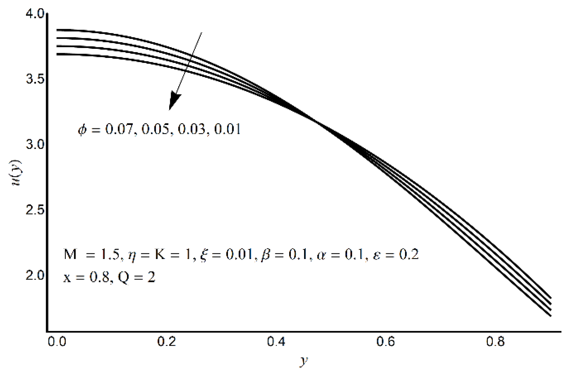
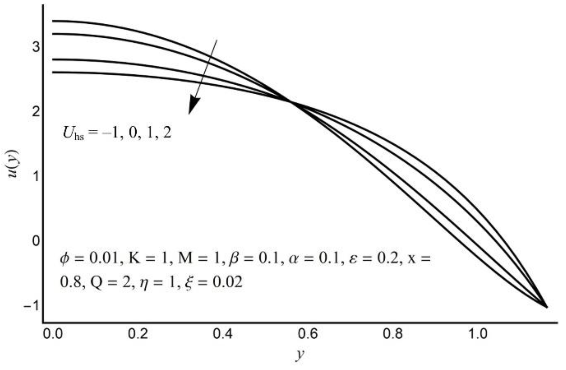
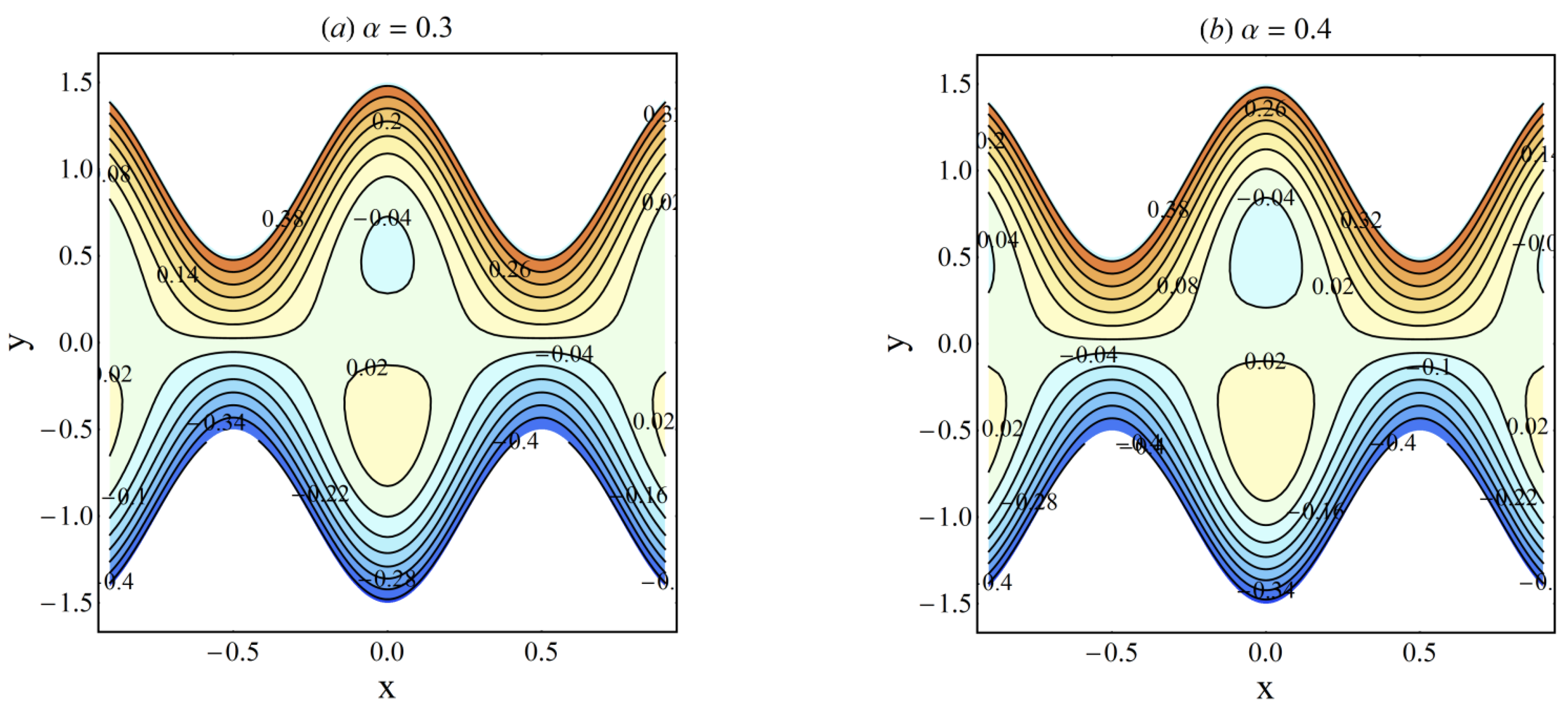
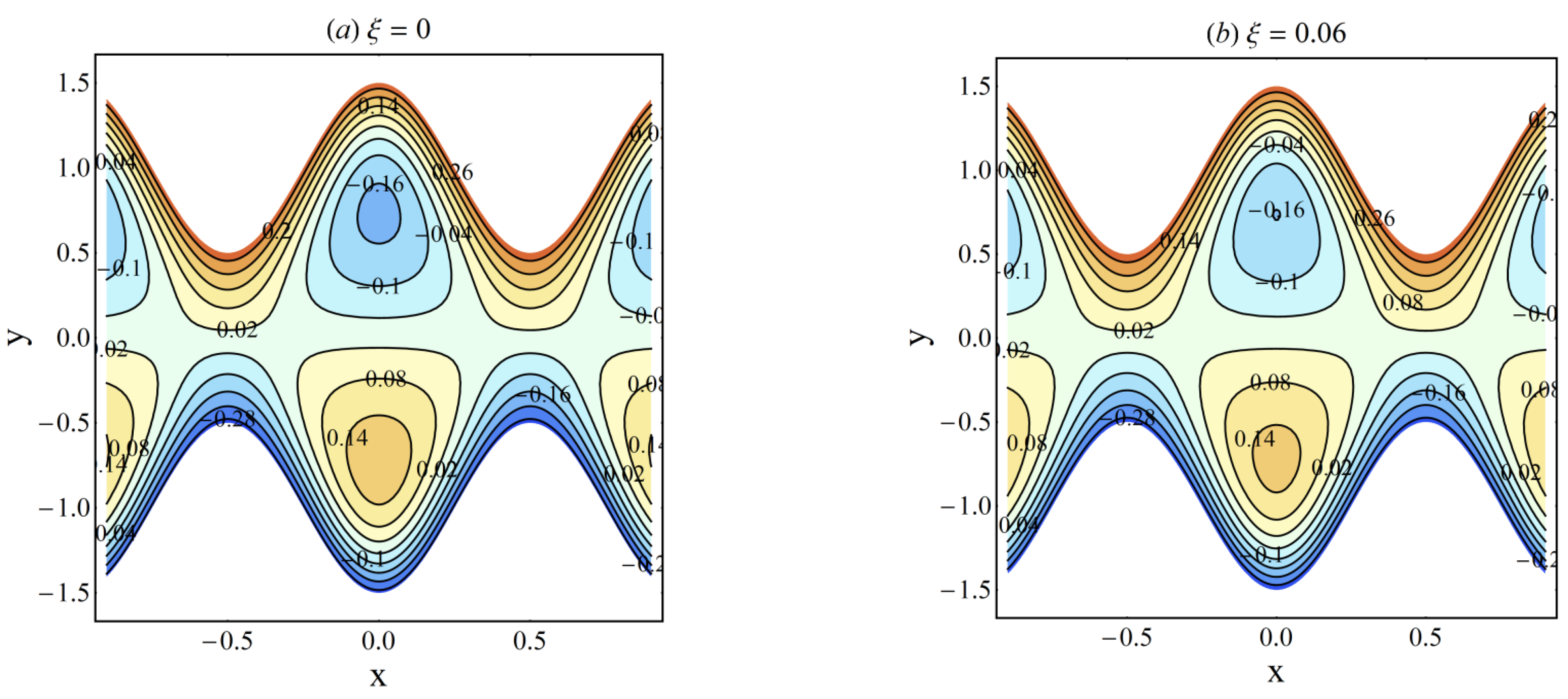
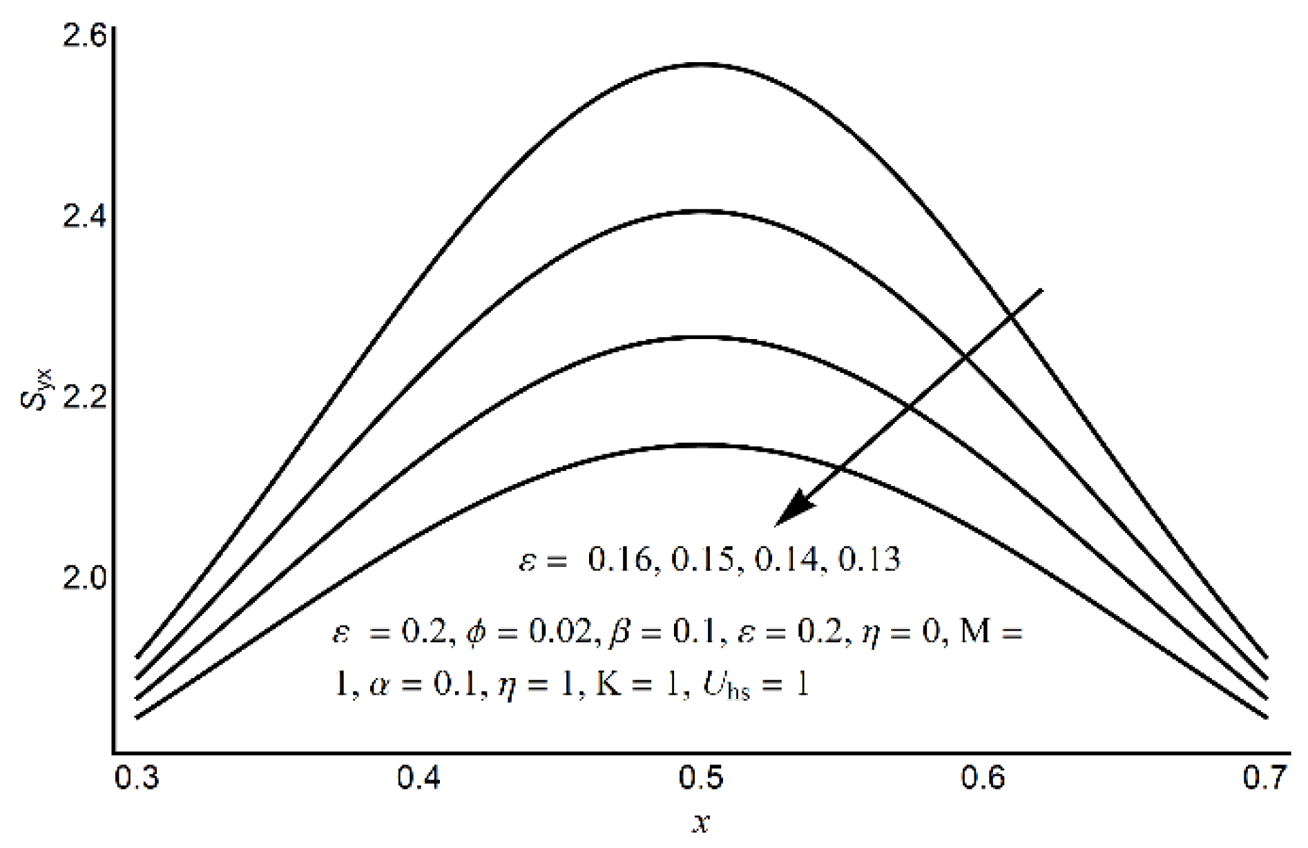
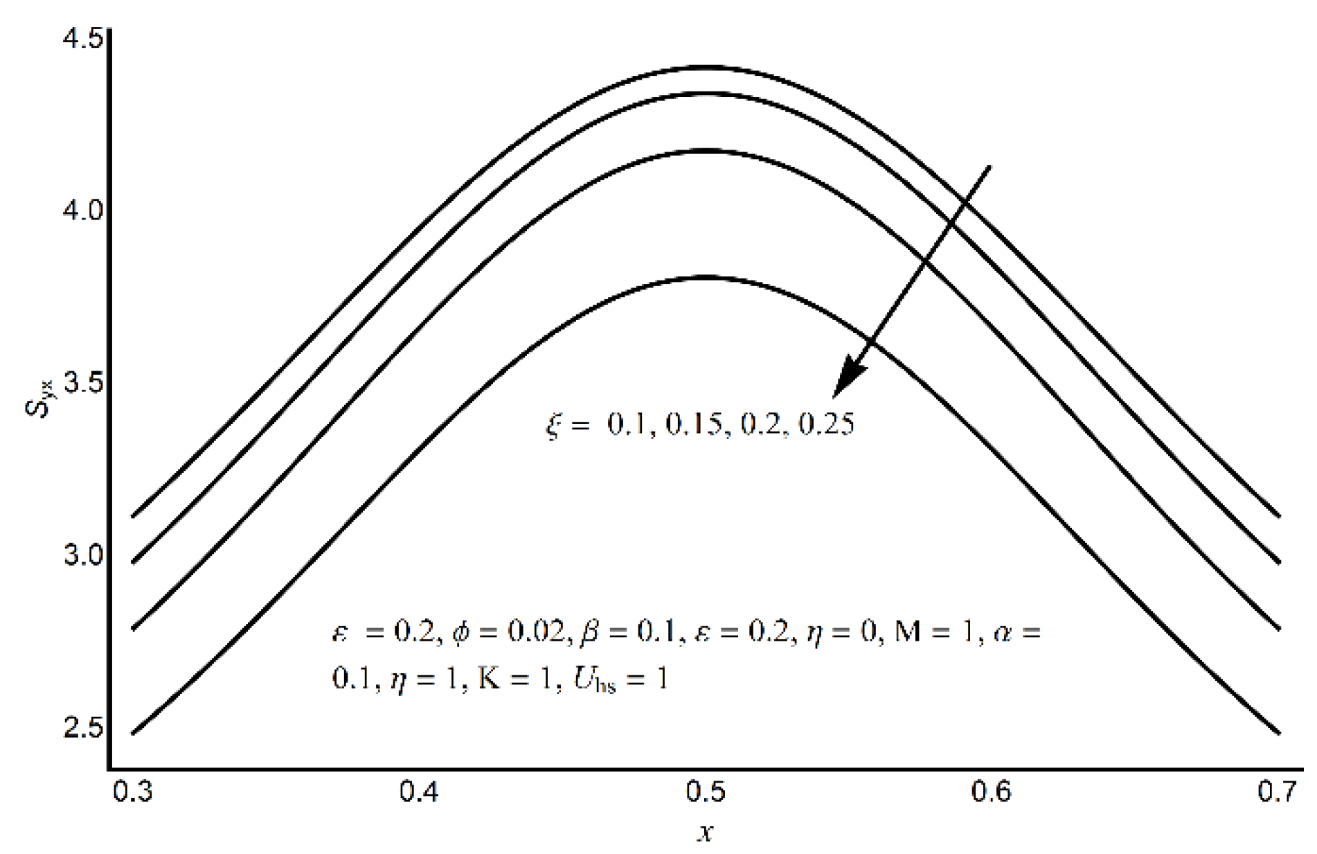
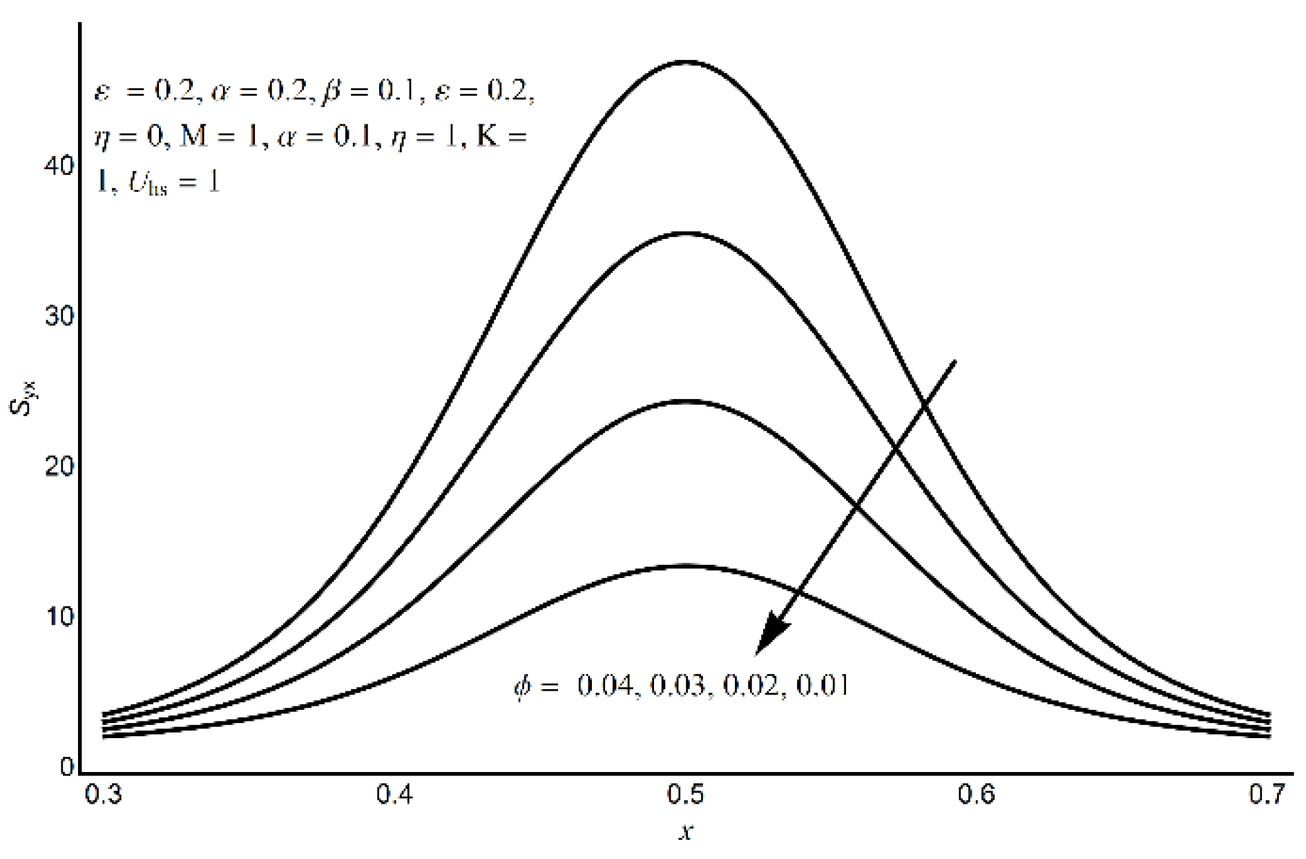
4. Results and Discussion

To discuss the effects of sundry parameters of interest on flow quantities such as axial velocity u(y), pressure gradient dp/dx, pressure rise per wavelength ∆P, shear stress τxy at the ciliated wall and trapping phenomenon, Figure 2, Figure 3, Figure 4, Figure 5, Figure 6, Figure 7, Figure 8, Figure 9, Figure 10, Figure 11, Figure 12, Figure 13, Figure 14, Figure 15, Figure 16, Figure 17, Figure 18, Figure 19, Figure 20, Figure 21, Figure 22 and Figure 23 are prepared.
Figure 2, Figure 3, Figure 4, Figure 5 and Figure 6 determine the effects of the Hartmann number (M), cilia length parameter (ε), Prandtl fluid parameter (ϕ), eccentricity parameter (α) and electro-osmotic parameter (K) on u(y). From Figure 2, it is noted that higher values of M cause more resistance to axial fluid flow and generate hindrance in the channel center region. However, near the edge zone, axial velocity accelerates for the same parameter values. Figure 3 is plotted to see the velocity profile for various values of Prandtl fluid time relaxation parameter ϕ. From the figure, it is noticed that the velocity profile describes two opposite patterns as ϕ increases. Near the boundary, the velocity decreases with ϕ, and in the center of channel the velocity increases, which is due to the mass balancing phenomenon at a certain cross-section. Figure 4 depicts the velocity profile for varying Helmholtz–Smoluchowski (HS) velocity Uhs.
The positive Uhs velocity indicates the exertion of electric current passes in the parallel direction of the flow stream, while the negative value indicates the electric current passes in the reverse direction. The velocity profile shows an increasing trend near the charged wall as Uhs increases, while an opposite behavior is noticed at the center caused by the cross sectional momentum balance.
The velocity is the decreasing (increasing) function of α at the channel centre (boundary), shown in Figure 5. Figure 6 discloses that the velocity profile alters by considering different values of parameter K through the elastic channel. In the locality of the channel center, a remarkable decline is associated with the fluid velocity for parameter K. Since electro-osmotic parameter is the ratio of ciliated channel height and Debye width; therefore, the behavior of K on the axial velocity near the ciliated boundary is quite opposite as compared with the channel center. Figure 7 portrays a 3D view of velocity profile versus x and y coordinates. From this figure, it can be observed that the fluid velocity is boosted at the channel center than the channel boundary. Moreover, the velocity is at maximum in the contracted part of the channel.
The effects of ε, α, ξ and K on pressure gradient versus volumetric flow rate can be visualized through Figure 8, Figure 9, Figure 10 and Figure 11. Figure 8 establishes that an increase in ε puts a strong acceleration in pressure gradient that may generate flow. Also, this proliferation is more substantial in the core region. From Figure 9, it is concluded favorable pressure gradient increases for small values of α. This increase is more visible at the channel center as compared to channel wall. Figure 10 states that adverse pressure gradient rises with a decrease in ξ, which produces reverse flow. Figure 11 describes that K has intensifying effects on pressure gradient throughout the channel. This rise is more considerable in the contracted portion of the flexible channel as compared to its wider part. To preserve the fluid volume in the narrow zone, a much-elevated pressure is required. It also reveals that the thinning or thickening of the size of the electric double-layer can control the pumping trend.
Figure 12, Figure 13, Figure 14 and Figure 15 show large values of ε and ϕ, which bring an increase in the pressure rise in the pumping region, but induce a drop in the augmented pumping region. In the pumping zone, the pressure rise per metachronal wavelength elevates for the small values of ξ and η but has the opposite effect in the augmented pumping zone. However, in the free pumping region, the effect of these parameters is negligible.
Another interesting occurrence of pumping ciliary flow called trapping is provided in Figure 16, Figure 17, Figure 18 and Figure 19. Trapping is the formation of internally circulating bolus of fluid locked by streamlines of propulsive waves. This confined bolus is propelled forward along with the metachronal wave (power and recovery strokes). Figure 16 depicts that the trapped bolus reduces in size when large values of M are taken into consideration. This indicates a sufficient decrease in the flow as the magnetic field increases and happens due to the strengthening of resistive Lorentz force. Figure 17 is plotted to see the stream pattern at different cilia length parameter ε. The figure indicates that the bolus size increases as ε increases. This behavior indicates the significant role of cilia structure in flow augmentation. From Figure 18, it is concluded that the trapped bolus expands in size for higher values of α. The trapped bolus shrinks when it is moved from no slip to partial slip condition, as shown in Figure 19. This is a common phenomenon that occurs due to decrease in shear forces as the slip length increases.
From Figure 20, it can be concluded that extended cilium can exert more force to hasten the fluid flow, which causes an elevation in shear stress at the flexible channel wall. Figure 21 depicts that shear stress considerably declines in the presence of high partial slip effects at the ciliated boundary. Moreover, the shear stress is high in the deep channel zone as compared to its edge portion. Figure 22 is sketched to show the wall shear stress for various values of eccentricity parameter α. The higher values of α show the elasticity of the cilia structure. The figure shows a clear increase in the shear stress as α increases. Since it was already evident from Figure 5 that higher α supports the fluid velocity; therefore, it is evident that the wall shear forces must increase with α. Figure 23 exhibits the shear stress for varying values of time relaxation parameter ϕ. The figure indicates a significant development of shear stress at the wall since the parameter ϕ is directly proportional to the wall shear stress.

5. Conclusions

A theoretical study revealing the significance of the electric field, magnetic field, and velocity slippage in pumping ciliary flow of Prandtl fluid is investigated in a symmetric ciliated channel. The flow is generated due to rhythmic (metachronal) waves of beatings of cilia. After employing lubrication approximations, governing equations are solved by perturbation technique. The following conclusions are from the study:
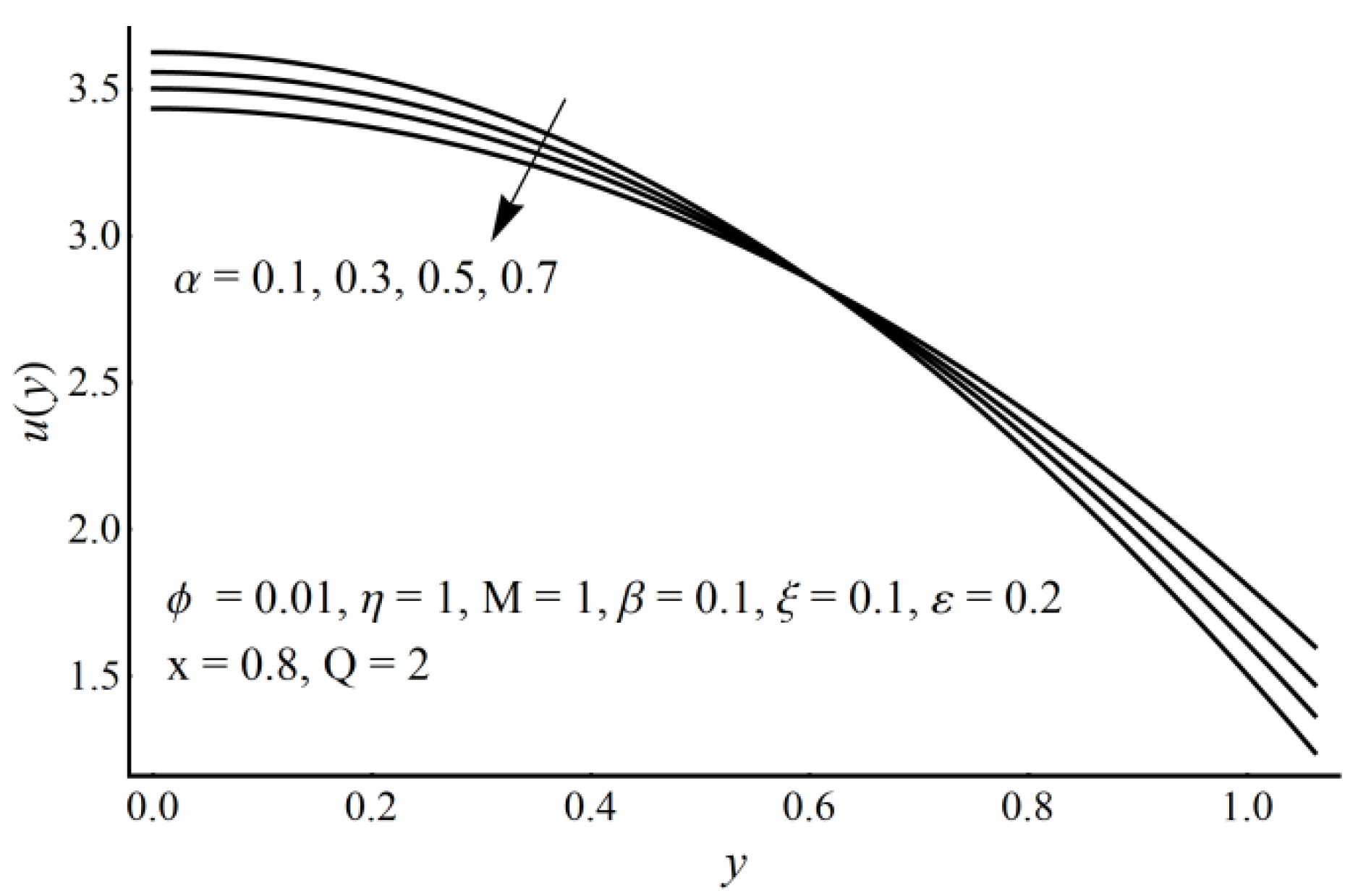
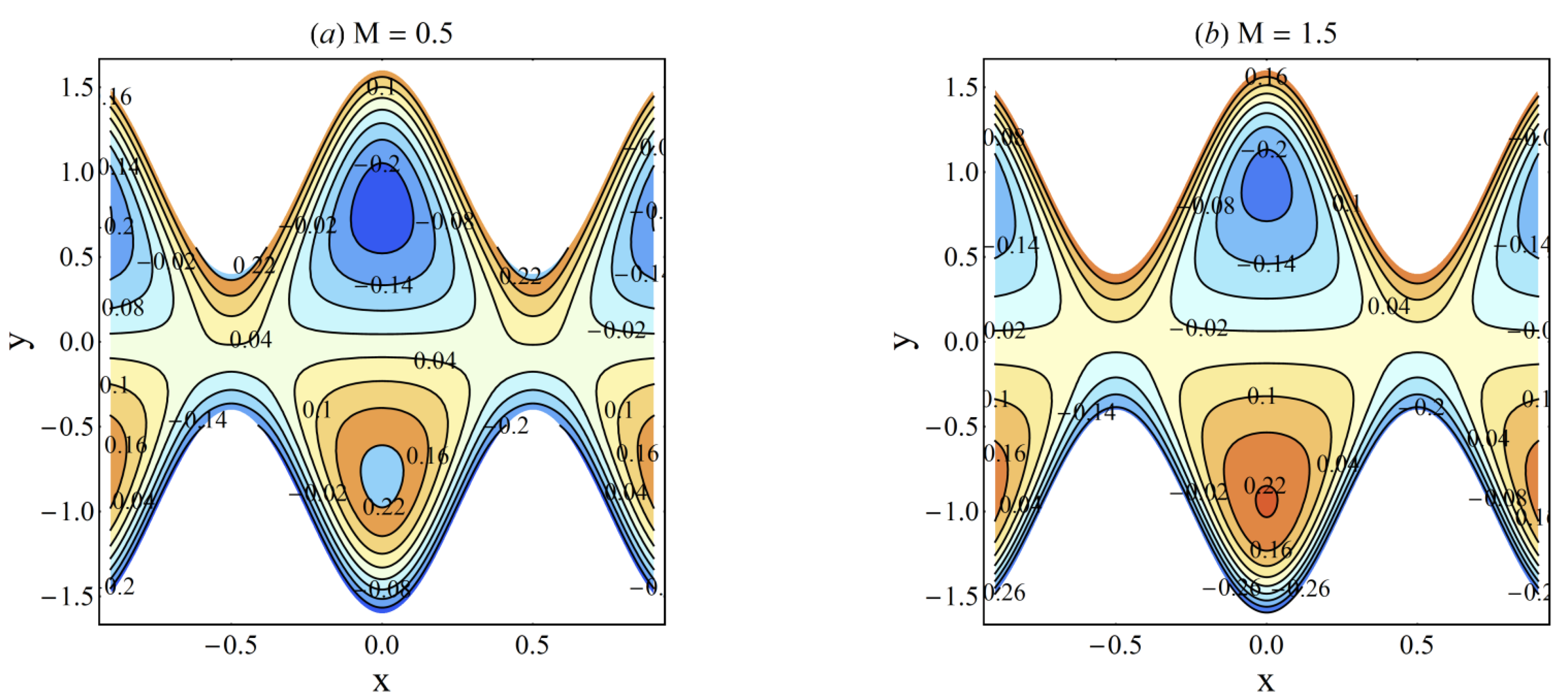
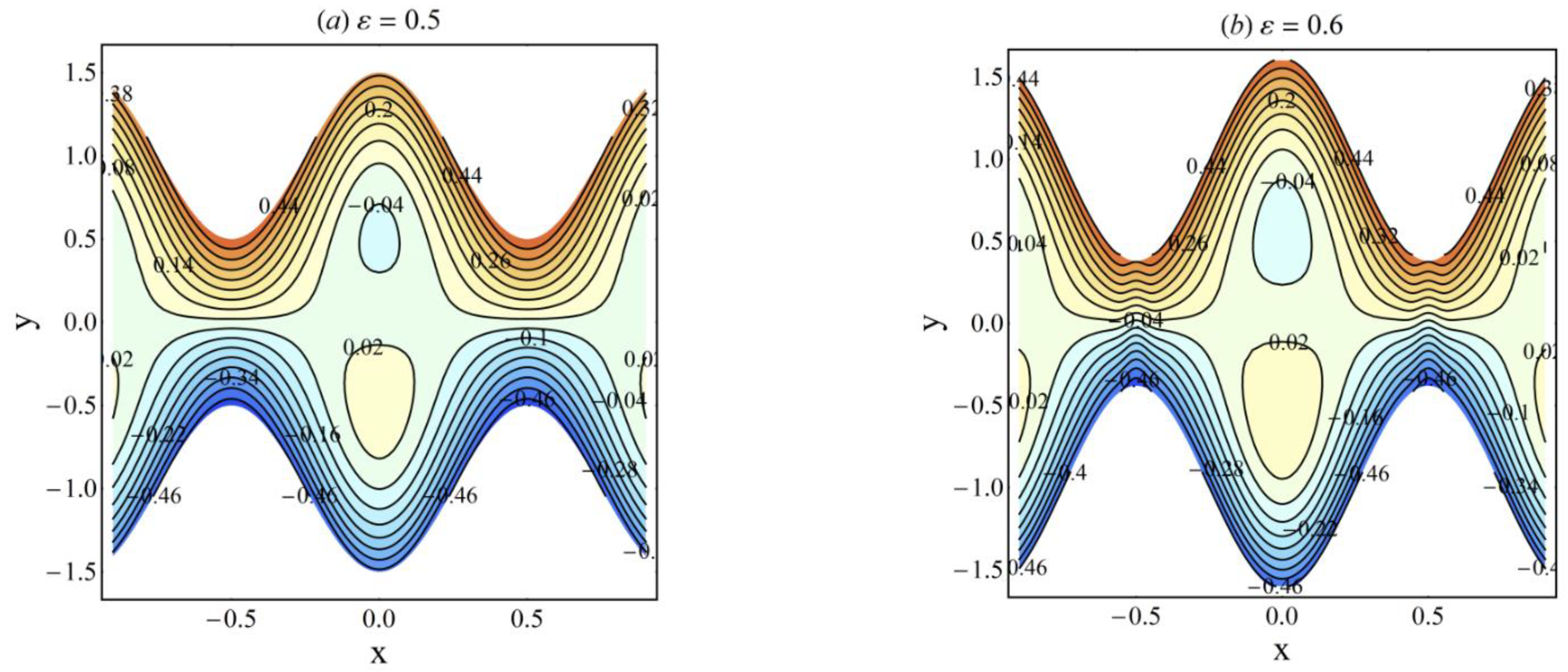
  • For large values of Hartmann number, cilia length, electro-osmotic and eccentricity parameter, axial velocity decreases at the channel center and increases near the ciliated wall region.
  • The Helmholtz–Smoluchowski velocity supports the fluid augmentation if applied in the direction of flow stream.
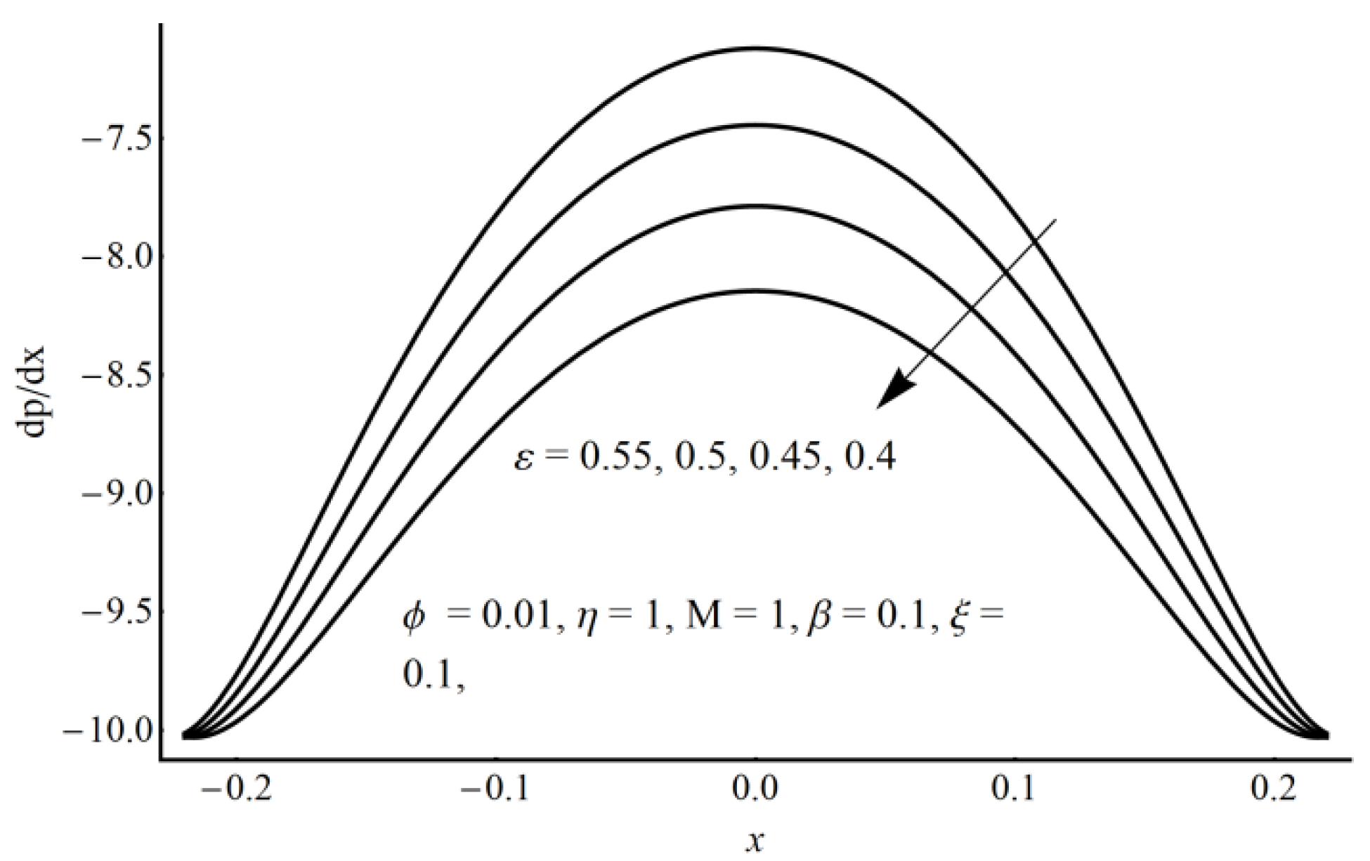
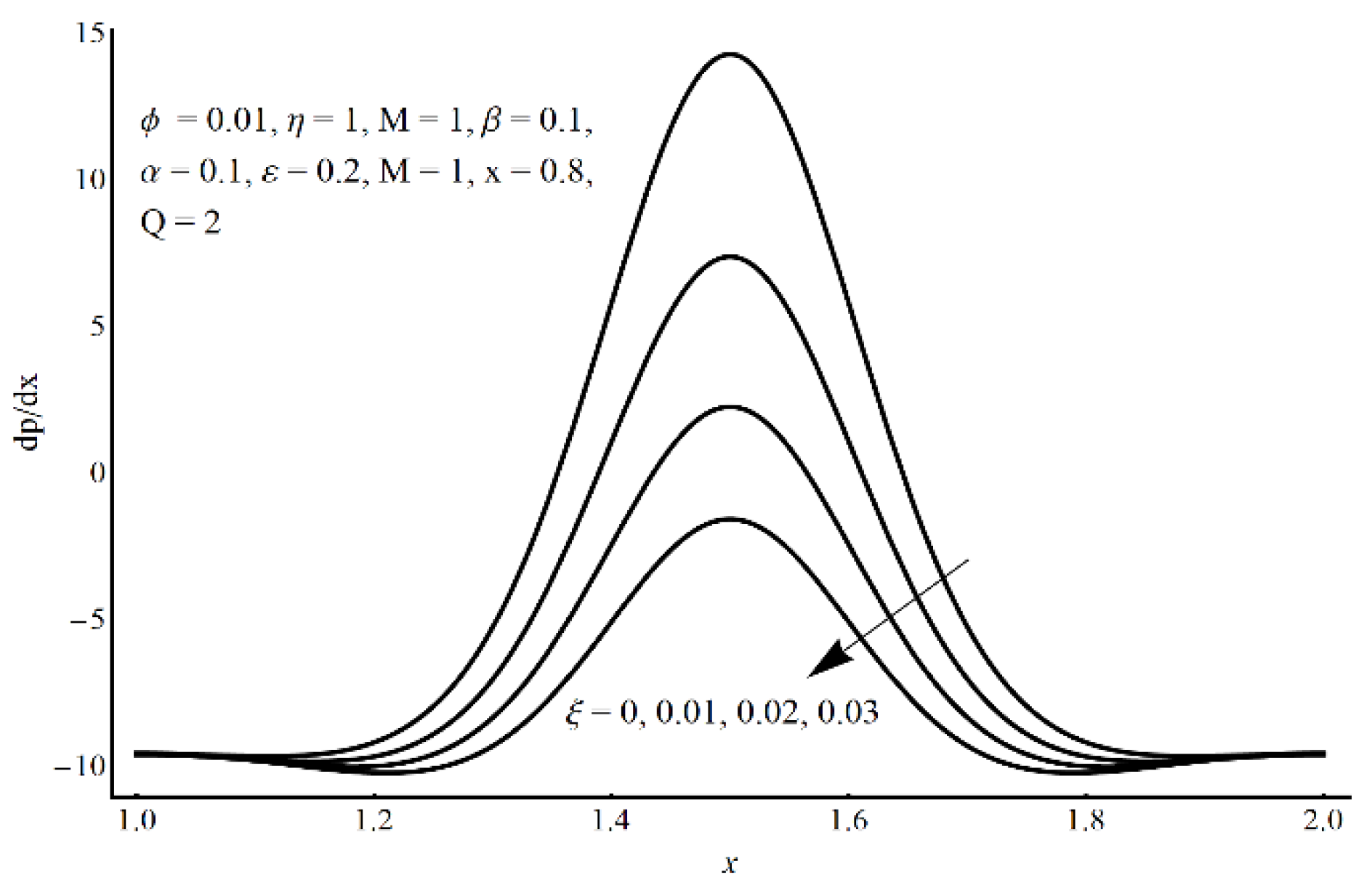
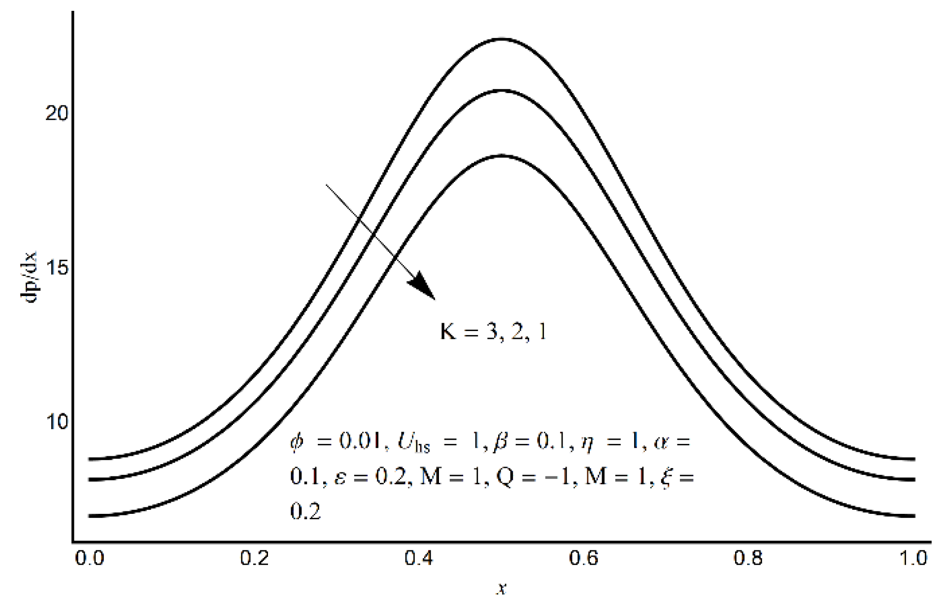
  • In the core region, a considerable elevation in the pressure gradient is obtained for the small values of the slippage parameter and the large values of cilia length and eccentricity parameters.
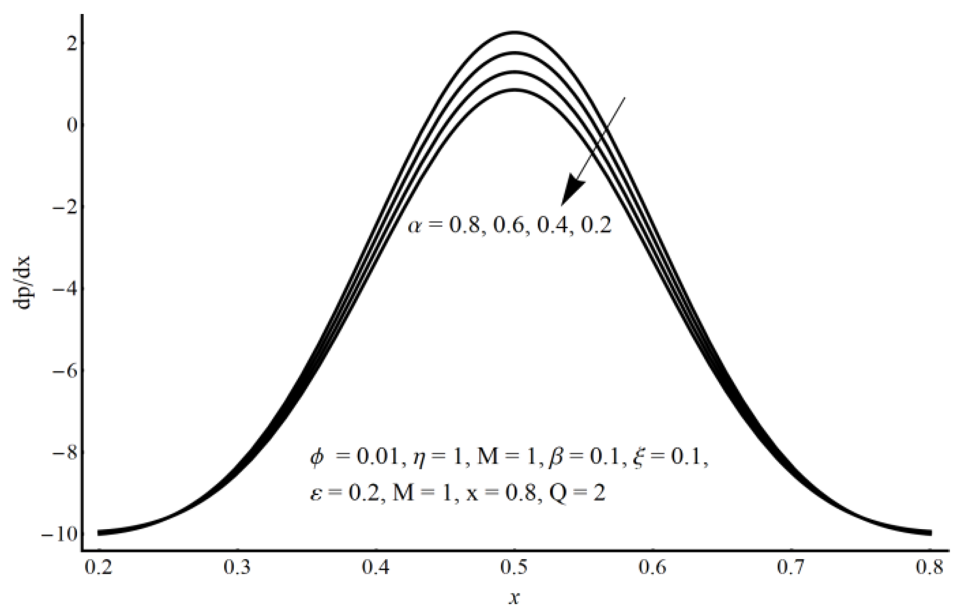
  • A more elevated pressure gradient is seen (for large values of electro-osmotic parameter) in the contracted channel zone than in the wider part of the channel.
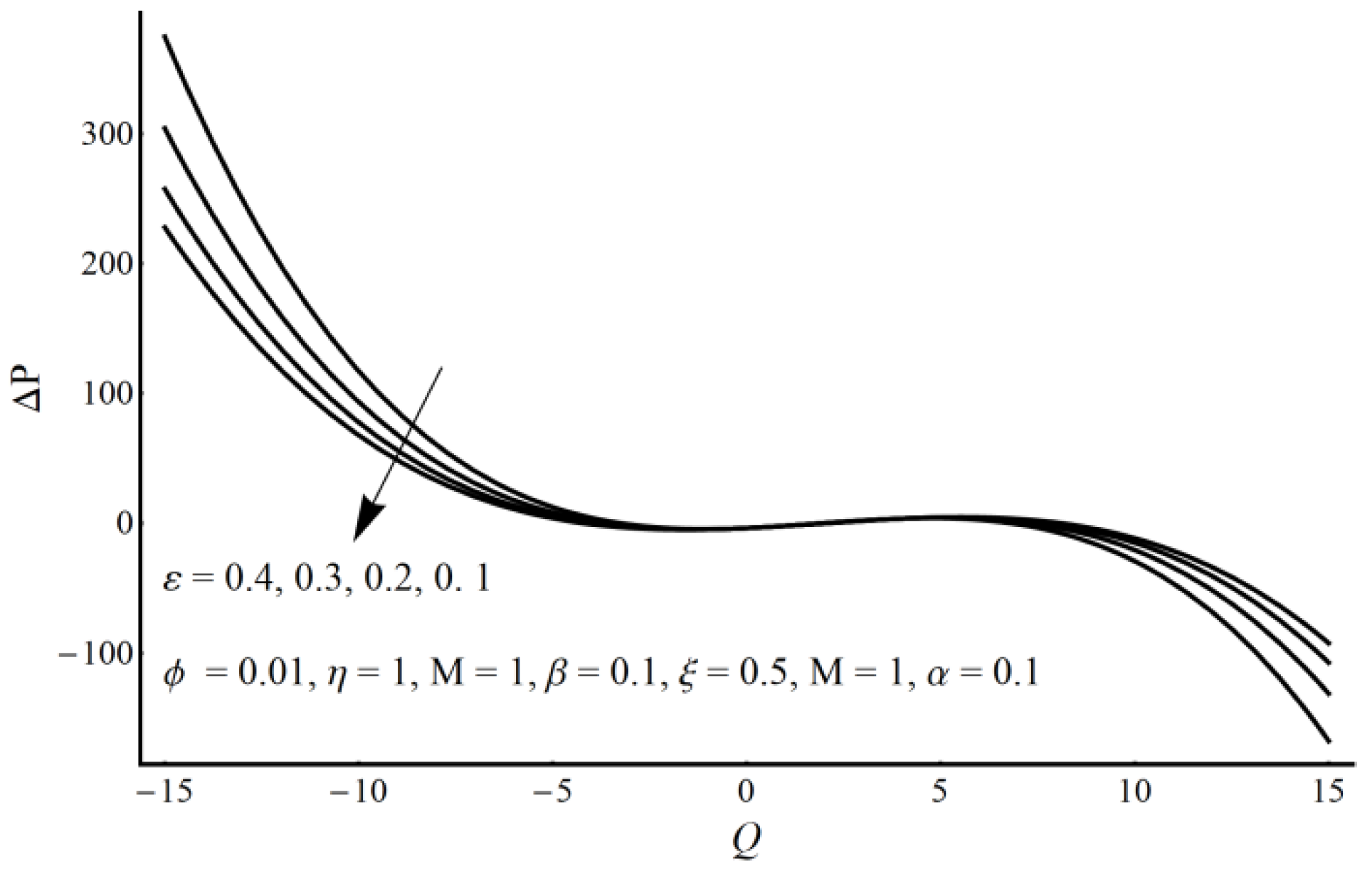
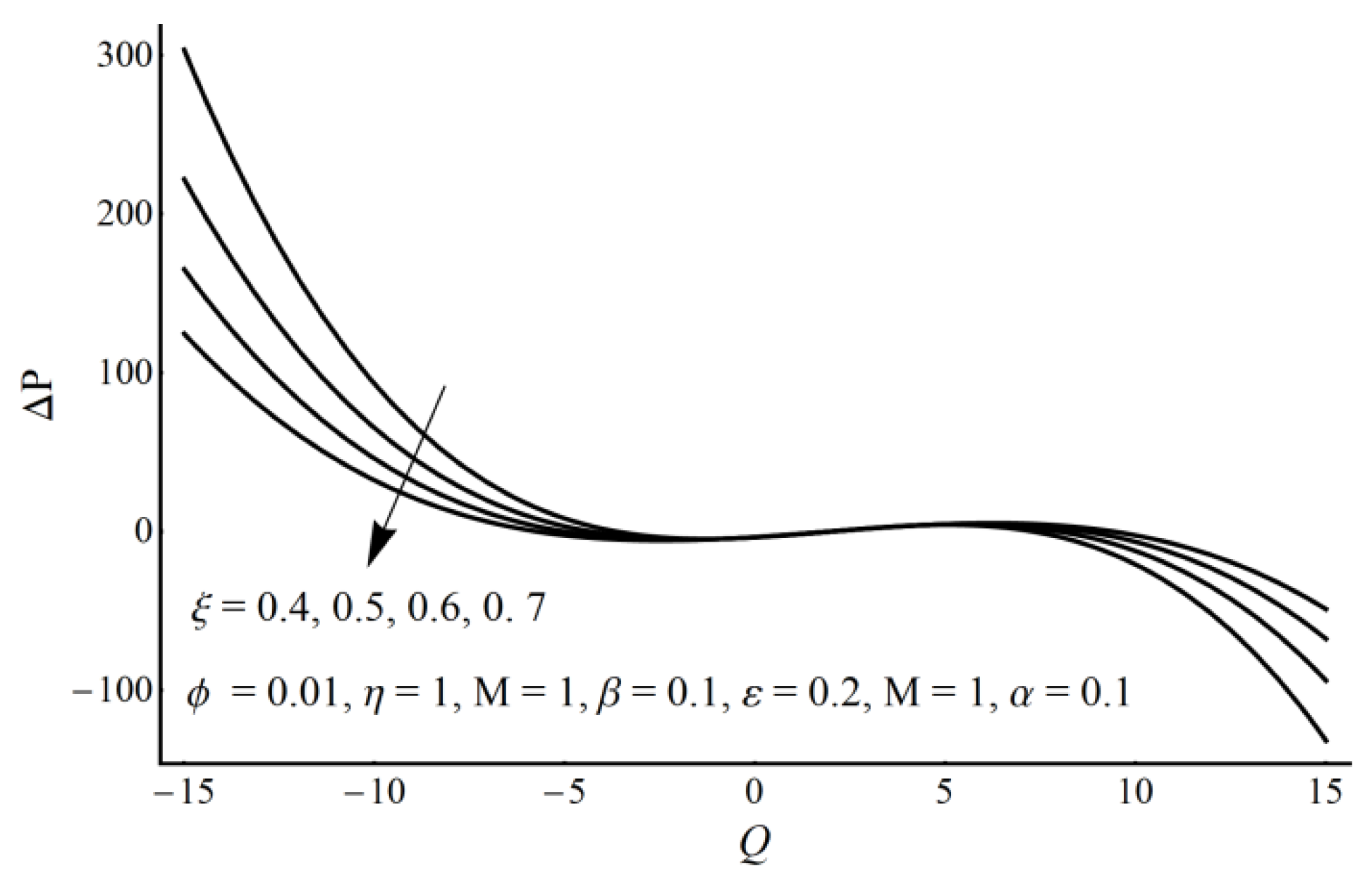
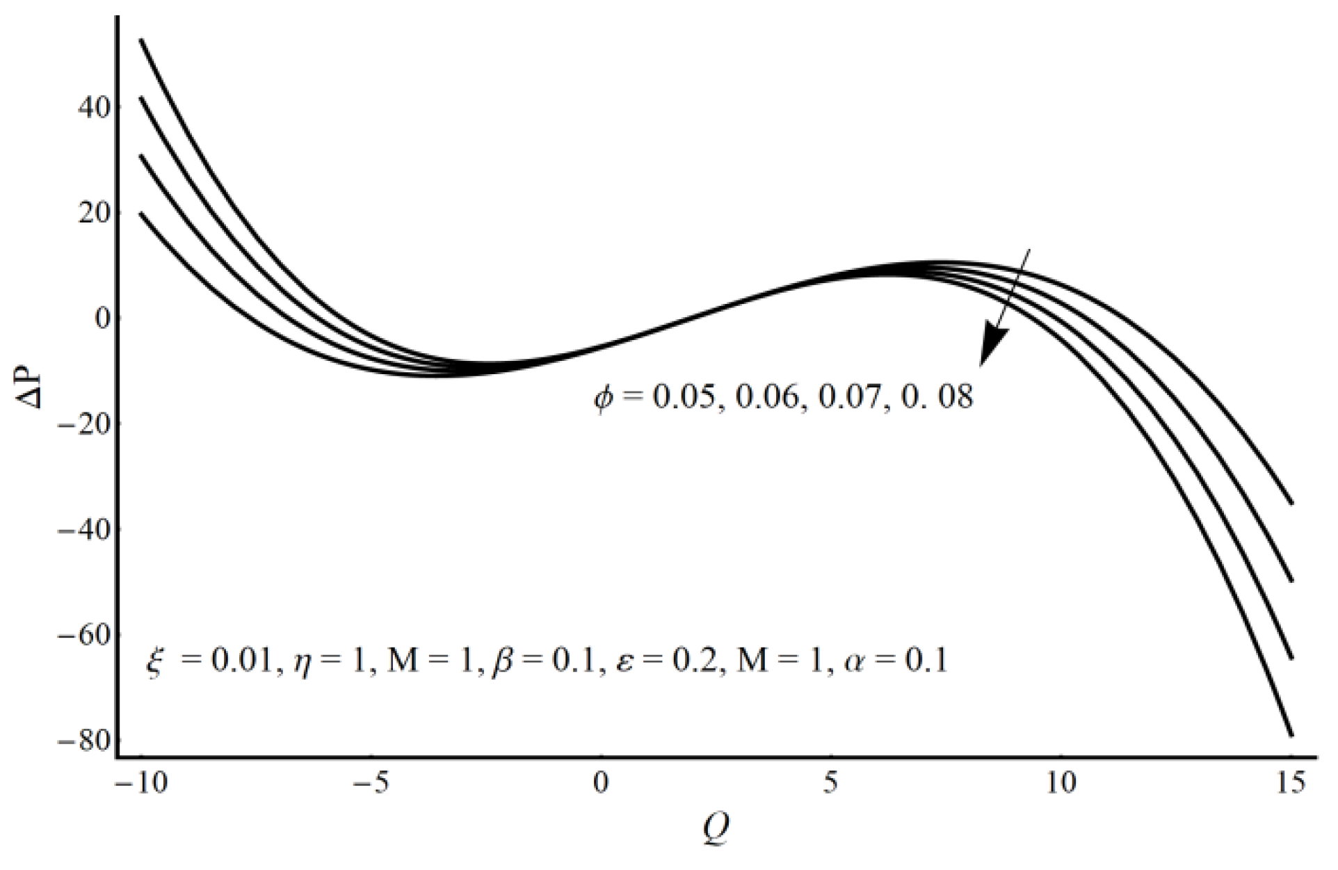
  • A pressure rise per wavelength is an increasing function of cilia length and perturbation parameter in the pumping region and shows the opposite behavior in the augmented pumping region.
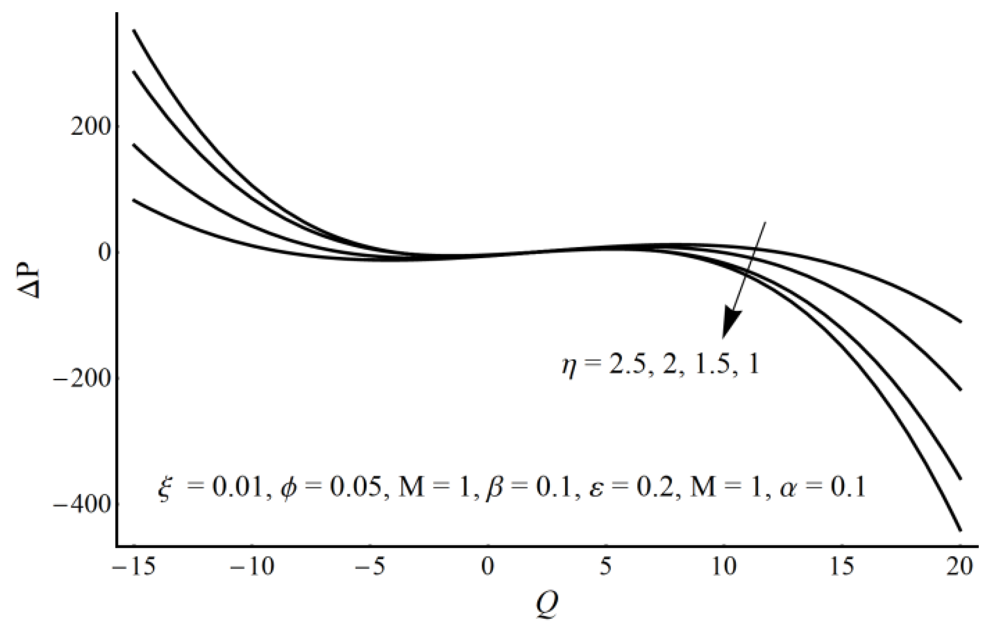
  • The pressure rise is an increasing function of the velocity slip parameter and Prandtl fluid parameter (η) in the augmented pumping region and a decreasing function in the pumping region.
  • Shear stress at the ciliated wall surface increases when large values of the cilia length and small velocity slip parameters are considered.
  • Shear stress becomes stronger for higher values of the eccentricity of cilia.

Funding

The author would like to acknowledge the support provided by the Deanship of Scientific Research (DSR) at Imam Abdulrahman Bin Faisal University for funding this work through project No. 2021-064-CBA.

Institutional Review Board Statement

Not applicable.

Informed Consent Statement

Not applicable.

Data Availability Statement

Not applicable.

Conflicts of Interest

The authors declare no conflict of interest

References

  1. Knowles, M.R.; Boucher, R.C. Mucus clearance as a primary innate defense mechanism for mammalian airways. J. Clin. Investig. 2002, 109, 571–577. [Google Scholar] [CrossRef]
  2. Bustamante-Marin, X.M.; Ostrowski, L.E. Cilia and mucociliary clearance. Cold Spring Harb. Perspect. Biol. 2017, 4, a028241. [Google Scholar] [CrossRef] [PubMed]
  3. Pablo, J.L.; DeCaen, P.G.; Clapham, D.E. Progress in ciliary ion channel physiology. J. Gen. Physiol. 2016, 1, 37–41. [Google Scholar] [CrossRef] [Green Version]
  4. Eddy, C.A.; Pauerstein, C.J. Anatomy and physiology of the fallopian tube. Clin. Obstet. Gynecol. 1980, 4, 1177–1193. [Google Scholar] [CrossRef] [PubMed]
  5. Ghazal, S.; Makarov, J.K.; de Jonge, C.J. Egg transport and fertilization. Glob. Libr. Women’s Med. 2014, 2014. [Google Scholar] [CrossRef]
  6. Lehti, M.S.; Sironen, A. Formation and function of sperm tail structures in association with sperm motility defects. Biol. Reprod. 2017, 97, 522–536. [Google Scholar] [CrossRef]
  7. Wheway, G.; Nazlamova, L.; Hancock, J.T. Signaling through the Primary Cilium. Front. Cell Dev. Biol. 2018, 6, 8. [Google Scholar] [CrossRef] [PubMed]
  8. Brennen, C. Oscillating-boundary layer theory for ciliary propulsion. J. Fluid Mech. 1974, 65, 799–824. [Google Scholar] [CrossRef] [Green Version]
  9. Qiu, T.; Lee, T.; Mark, A.G.; Morozov, K.I.; Münster, R.; Mierka, O.; Turek, S.; Leshansky, A.M.; Fischer, P. Swimming by reciprocal motion at low Reynolds number. Nat. Commun. 2014, 5, 1–8. [Google Scholar] [CrossRef] [Green Version]
  10. Eytan, O.; Elad, D. Analysis of intra-uterine fluid motion induced by uterine contractions. Bull. Math. Biol. 1999, 61, 221–238. [Google Scholar] [CrossRef] [PubMed]
  11. Farooq, A.A.; Tripathi, D.; Elnaqeeb, T. Tripathi and Elnaqeeb, On the propulsion of micropolar fluid inside a channel due to ciliary induced metachronal wave. Appl. Math. Comput. 2019, 347, 225–235. [Google Scholar]
  12. Farooq, A.A.; Siddiqui, A.M. Mathematical model for the ciliary-induced transport of seminal liquids through the ductuli efferentes. Int. J. Biomath. 2017, 10, 1750031. [Google Scholar] [CrossRef]
  13. Ponalagusamy, R. Mathematical analysis of flow of non-Newtonian fluid due to metachronal beating of cilia in a tube and its physiological applications. Appl. Math. Comput. 2018, 337, 545–561. [Google Scholar] [CrossRef]
  14. Ezzat, M.; Djahanbakhch, O.; Arian, S.; Carr, B.R. Tubal transport of gametes and embryos: A review of physiology and pathophysiology. J. Assist. Reprod. Genet. 2014, 10, 1337–1347. [Google Scholar] [CrossRef] [Green Version]
  15. Stud, K.; Sephon, G.S.; Mishra, R.K. Pumping action on blood flow by a magnetic field. Bull. Math. Biol. 1977, 39, 385–390. [Google Scholar]
  16. Kothandapani, M.; Srinivas, S. Peristaltic transport of a Jeffrey fluid under the effect of magnetic field in an asymmetric channel. Int. J. Nonlinear Mech. 2008, 43, 915. [Google Scholar] [CrossRef]
  17. Maqbool, K.; Shaheen, S.; Mann, A.B. Exact solution of cilia induced flow of a Jeffrey fluid in an inclined tube. Springerplus 2016, 5, 1379. [Google Scholar] [CrossRef] [Green Version]
  18. Hayat, T.; Saleem, N.; Mesloub, S.; Ali, N. Magnetohydrodynamic Flow of a Carreau Fluid in a Channel with Different Wave Forms. Z. Nat. A 2011, 66, 215–222. [Google Scholar]
  19. Ramesh, K.; Tripathi, D.; Beg, O.A. Cilia-assisted hydromagnetic pumping of biorheological couple stress fluids. J. Propuls. Power 2019, 8, 221–233. [Google Scholar] [CrossRef]
  20. Sehra; Haq, S.; Shah, S.I.A.; Nisar, K.S.; Jan, S.U.; Khan, I. Convection heat mass transfer and MHD flow over a vertical plate with chemical reaction, arbitrary shear stress and exponential heating. Sci. Rep. 2021, 11, 4265. [Google Scholar] [CrossRef]
  21. Saleem, N.; Munawar, S. A mathematical analysis of MHD blood flow of Erying-Powell fluid through a constricted artery. Int. J. Biomath. 2016, 9, 1650017. [Google Scholar] [CrossRef]
  22. Akram, S.; Afzal, F.; Imran, M. Influence of metachronal wave on hyperbolic tangent fluid model with inclined magnetic field. Int. J. Geom. Methods Mod. Phys. 2019, 16, 1950139. [Google Scholar] [CrossRef]
  23. Burgreen, D.; Nakache, F.R. Electrokinetic flow in ultrafine capillary slits. J. Phys. Chem. 1964, 68, 1084–1091. [Google Scholar] [CrossRef]
  24. Yang, C.; Li, D. Electrokinetic Effects on Pressure-Driven Liquid Flows in Rectangular Microchannels. J. Colloid Interface Sci. 1997, 194, 95–107. [Google Scholar] [CrossRef] [PubMed]
  25. Chaube, M.K.; Yadav, A.; Tripathi, D. Electroosmotic flow of biorheological micropolar fluids through microfluidic channels. Korea-Aust. Rheol. J. 2018, 30, 89–98. [Google Scholar] [CrossRef]
  26. Akram, S.; Zafar, M.; Nadeem, S. Peristaltic transport of a Jeffrey fluid with double-diffusive convection in nanofluids in the presence of inclined magnetic field. Int. J. Geom. Methods Mod. Phys. 2018, 15, 1850181. [Google Scholar] [CrossRef]
  27. Jayavel, P.; Jhorar, R.; Tripathi, D. Electroosmotic flow of pseudoplastic nanoliquids via peristaltic pumping. J. Braz. Soc. Mech. Sci. Eng. 2019, 41, 61. [Google Scholar] [CrossRef]
  28. Hang, H.U.; Pop, I.; Sun, Q. Fluid flow driven along microchannel by its upper stretching wall with electrokinetic effects. Appl. Math. Mech. Engl. Ed. 2018, 39, 395–408. [Google Scholar]
  29. Tripathi, D.; Yadav, A.; Bég, O.; Kumar, R. Study of microvascular non-Newtonian blood flow modulated by electroosmosis. Microvasc. Res. 2017, 117, 28–36. [Google Scholar] [CrossRef]
  30. Akram, J.; Akbar, N.; Maraj, E.N. A comparative study on the role of nanoparticle dispersion in electroosmosis regulated peristaltic flow of water. Alex. Eng. J. 2020, 59, 943–956. [Google Scholar] [CrossRef]
  31. Foster, W.M. Mucociliary Transport and Cough in Humans. Pulm. Pharmacol. Ther. 2002, 15, 277–282. [Google Scholar] [CrossRef]
  32. Taherali, F.; Varum, F.; Basit, A.W. A slippery slope: On the origin, role and physiology of mucus. Adv. Drug Deliv. Rev. 2018, 124, 16–33. [Google Scholar] [CrossRef]
  33. Baltz, J.M.; Williams, P.O.; Cone, R.A. Dense fibers protect mammalian sperm against damage. Biol. Reprod. 1990, 43, 485–491. [Google Scholar] [CrossRef] [Green Version]
  34. Tripathi, D.; Beg, O.A.; Curiel-Sosa, J.L. Homotopy semi-numerical simulation of peristaltic flow of generalised Oldroyd-B fluids with slip effects. Comput. Biomech. Biomed. Eng. 2014, 17, 433–442. [Google Scholar] [CrossRef]
  35. Makinde, O.D.; Reddy, M.G.; Reddy, K.V. Effects of thermal radiation on MHD peristaltic motion of walters-B fluid with heat source and slip conditions. J. Appl. Fluid Mech. 2017, 10, 1105–1112. [Google Scholar] [CrossRef]
  36. Hayat, T.; Saleem, N.; Hendi, A.A. Slip and Heat Transfer Effects on Peristaltic Motion of a Carreau Fluid in an Asymmetric Channel. Z. Nat. A 2010, 65, 1121–1127. [Google Scholar] [CrossRef]
  37. Hayat, T.; Saleem, N.; Hendi, A.A. A Mathematical Model for Studying the Slip Effect on Peristaltic Motion with Heat and Mass Transfer. Chin. Phys. Lett. 2011, 28, 034702. [Google Scholar] [CrossRef]
  38. Chaube, M.K.; Tripathi, D.; Beg, O.A.; Sharma, S.; Pandey, V.S. Peristaltic creeping flow of power law physiological fluids through a nonuniform channel with slip effect. Appl. Bionics Biomech. 2015, 2015, 152802. [Google Scholar] [CrossRef] [Green Version]
  39. Munawar, S.; Saleem, N. Entropy Analysis of an MHD Synthetic Cilia Assisted Transport in a Microchannel Enclosure with Velocity and Thermal Slippage Effects. Coatings 2020, 10, 414. [Google Scholar] [CrossRef]
  40. Ijaz, S.; Saleem, N.; Munawar, S. Slip effect on the magnetohydrodynamics channel flow in the presence of the across mass transfer phenomenon. J. Appl. Mech. Tech. Phys. 2017, 58, 54–62. [Google Scholar] [CrossRef]
  41. Ramesh, K. Effects of slip and convective conditions on the peristaltic flow of couple stress fluid in an asymmetric channel through porous medium. Comput. Meth. Prog. Biomed. 2016, 135, 1–14. [Google Scholar] [CrossRef]
  42. Saleem, N.; Munawar, S. Entropy analysis in cilia driven pumping flow of hyperbolic tangent fluid with magnetic field effects. Fluid Dyn. Res. 2020, 52, 025503. [Google Scholar] [CrossRef]
  43. Patel, M.; Timol, M.G. The stress strain relationship for viscousinelastic non-Newtonian fluids. Int. J. Appl. Math. Mech. 2010, 6, 79–93. [Google Scholar]
  44. Alsaedi, A.; Batool, N.; Yasmin, H.; Hayat, T. Convective Heat Transfer Analysis on Prandtl Fluid Model with Peristalsis. Appl. Bionics Biomech. 2013, 10, 197–208. [Google Scholar] [CrossRef]
Figure 1. Flow configuration of electro-osmosis and cilia in the channel.
Lubricants 09 00048 g001
Figure 2. Axial velocity for different values of variable M.
Lubricants 09 00048 g002
Figure 3. Axial velocity for different values of variable ϕ.
Lubricants 09 00048 g003
Figure 4. Axial velocity for different values of variable ξ.
Lubricants 09 00048 g004
Figure 5. Axial velocity for different values of variable α.
Lubricants 09 00048 g005
Figure 6. Axial velocity for different values of variable K.
Lubricants 09 00048 g006
Figure 7. A 3-D view of velocity when M = 1, α = 0.2, ϕ = 0.03, ε = β = 0.1, ξ = 0.02, η = 1.
Lubricants 09 00048 g007
Figure 8. Pressure gradient for different values of variable ε.
Lubricants 09 00048 g008
Figure 9. Pressure gradient for different values of variable α.
Lubricants 09 00048 g009
Figure 10. Pressure gradient for different values of variable.
Lubricants 09 00048 g010
Figure 11. Pressure gradient for different values of variable K.
Lubricants 09 00048 g011
Figure 12. Pressure rise per wavelength for different values of ε.
Lubricants 09 00048 g012
Figure 13. Pressure rise per wavelength for different values of ξ.
Lubricants 09 00048 g013
Figure 14. Pressure rise per wavelength for different values of ϕ.
Lubricants 09 00048 g014
Figure 15. Pressure rise per wavelength for different values of η.
Lubricants 09 00048 g015
Figure 16. Stream function for M when α = 0.2, ϕ = 0.03, ε = β = 0.1, ξ = 0.02, η= 1, Q = 0.4.
Lubricants 09 00048 g016
Figure 17. Stream function for ε when α = 0.2, ϕ = 0.03, β = 0.1, ξ = 0.02, M = η = 1, Q = 0.4.
Lubricants 09 00048 g017
Figure 18. Stream function for α when ε = 0.2, ϕ = 0.03, β = 0.1, ξ = 0.02, M = η = 1, Q = 0.4.
Lubricants 09 00048 g018
Figure 19. Stream function for ξ when ε = 0.2, ϕ = 0.03, β = 0.1, α = 0.1, M = η = 1, Q = 0.4.
Lubricants 09 00048 g019
Figure 20. Shear stress at the ciliated wall for different values of ε.
Lubricants 09 00048 g020
Figure 21. Shear stress at the ciliated wall for different values of ε.
Lubricants 09 00048 g021
Figure 22. Shear stress at the ciliated wall for different values of α.
Lubricants 09 00048 g022
Figure 23. Shear stress at the ciliated wall for different values of ϕ.
Lubricants 09 00048 g023
Table 1. A comparison of the present analytic solution with a numerical result by the shooting method when Q = 2, α = ε = 0.2, K = 1, ϕ = 0.01, η = 1, x = 0.5, Uhs = 1 are fixed.
MΨ″(h) (Analytic)Ψ″(h) (Numerical)
0.5−11.5061−11.5171
1−11.7651−11.7837
1.5−12.2013−12.2129
2−12.7451−12.7830
2.5−13.3785−13.4664
Publisher’s Note: MDPI stays neutral with regard to jurisdictional claims in published maps and institutional affiliations.

