Tribological Evaluation of Turbostratic 2D Graphite as Oil Additive

 ,
, 
Abstract
1. Introduction
2. Materials and Methods
2.1. Synthesis, Extraction and Characterization of Turbostratic Graphite

2.2. Tribological Evaluation
2.2.1. Preparation of Turbostratic 2D Graphite-Based Nanofluids
2.2.2. Tribological Characterization

3. Results and Discussion
3.1. Characterization of Extracted Particles
3.2. Tribological Characterization
3.2.1. Incremental Load Tests

3.2.2. Constant Load Tests


4. Conclusions
- The powder obtained was analysed (XRD, Raman spectroscopy, SEM, and TEM) and characterized as turbostratic 2D graphite;
- The hydrodynamic diameter distribution of the turbostratic 2D graphite-based nanofluid shows a bimodal distribution with modes of 1.720 and 3.090 nm;
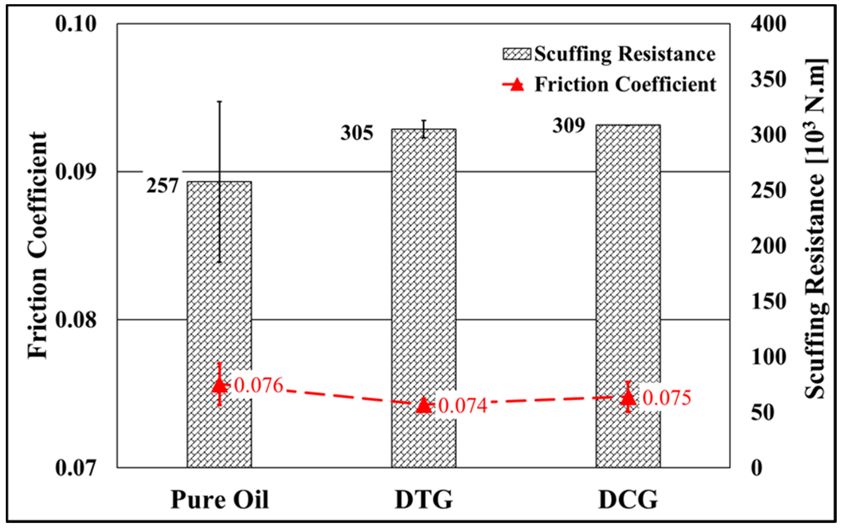
- The values for the scuffing resistance and friction coefficient obtained in the lubricious regime of the incremental load tests are statistically equivalent regardless of the lubricant. However, the stability of both the scuffing resistance and, to a lesser extent, of the friction coefficient is higher for the tests conducted with the nanofluids;
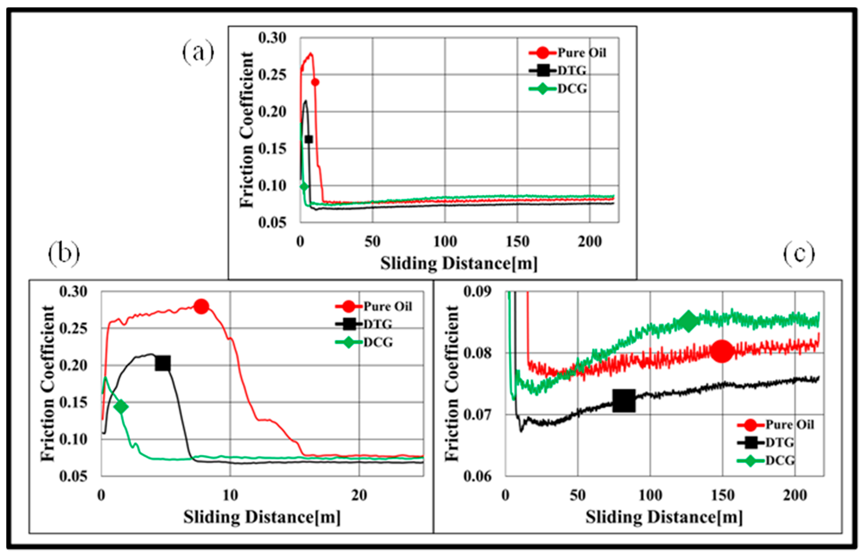
- The evolution of the friction coefficient with sliding distance in the constant load tests showed similar behaviour regardless of the lubricant, that is, a maximum followed by a progressive decay to the steady-state value. However, the time to achieve the steady-state regime, the maximum friction coefficient, and the average value of the steady-state friction coefficient varied, being higher for the tests conducted with pure oil as the lubricant. For nanofluids, these parameters could be associated with the hydrodynamic diameter distribution at the beginning of the tests: a smaller hydrodynamic diameter (DCG) induced shorter times and lower friction coefficient maximum but higher friction coefficient;
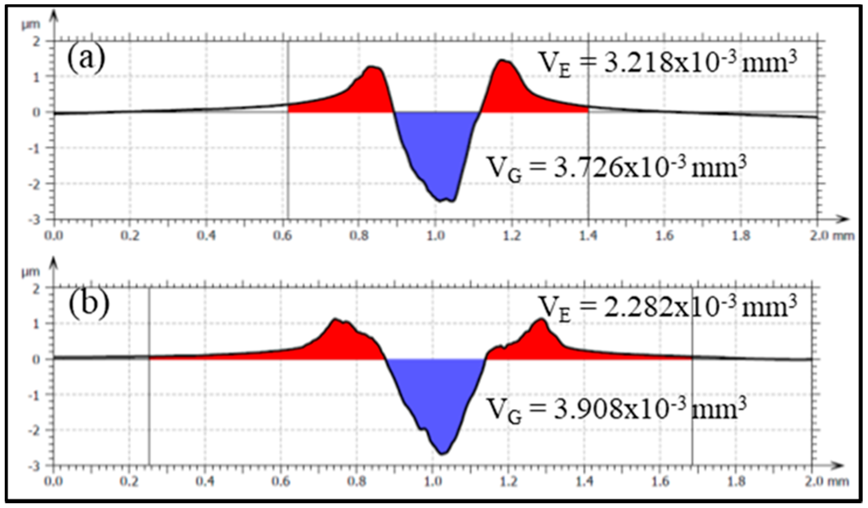
- The use of carbon-based nanoparticles as a lubricant oil additive reduces the wear rate of the tribological system. The DTG nanofluid induced the lowest wear rate of the specimens but did not show the best performance concerning the counter-bodies. The reductions in the average wear rate for the specimens and counter-body were 26% and 47%, respectively, in the DTG tests compared to the pure oil tests. This demonstrates the excellent performance of turbostratic 2D graphite nanoparticles as a lubricant additive; and
- The wear mechanisms acting on the samples differed: the tracks observed for tests using turbostratic 2D graphite-based nanofluid provide evidence of abrasive wear on their edges and the predominance, particularly in the central part of the wear mark, of tribo-chemical wear, represented by the almost continuous presence of numerous islands of turbostratic 2D graphite-rich tribolayers. On the other hand, specimens used in tests with pure oil and commercial 3D graphite show evidence of abrasive wear associated with detachments heterogeneously distributed throughout the central region and, in the case of pure oil, small evenly distributed oxygen-rich tribolayer islands.
5. Patents
Author Contributions
Funding
Acknowledgments
Conflicts of Interest
References
- Binder, C.; Hammes, G.; Schroeder, R.; Klein, A.N.; de Mello, J.D.B.; Binder, R. “Fine tuned” steels point the way to a focused future. Metal Powder Rep. 2010, 65, 29–37. [Google Scholar] [CrossRef]
- de Mello, J.D.B.; Binder, C.; Binder, R.; Klein, A.N. Effect of precursor content and sintering temperature on the scuffing resistance of sintered self lubricating steel. Wear 2011, 271, 1862–1867. [Google Scholar] [CrossRef]
- De Mello, J.D.B.; Binder, C.; Hammes, G.; Klein, A.N. Effect of the metallic matrix on the sliding wear of plasma assisted debinded and sintered MIM self-lubricating steel. Wear 2013, 301, 648–655. [Google Scholar] [CrossRef]
- de Mello, J.D.B.; Binder, R. A methodology to determine surface durability in multifunctional coatings applied to soft substrates. Tribol. Int. 2006, 39, 769–773. [Google Scholar] [CrossRef]
- Binder, C.; Bendo, T.; Pereira, R.V.; Hammes, G.; De Mello, J.D.B.; Klein, A.N. Influence of the SiC content and sintering temperature on the microstructure, mechanical properties and friction behaviour of sintered self-lubricating composites. Powder Metal 2016, 59, 384–393. [Google Scholar] [CrossRef]
- Donnet, C.; Erdemir, A. Historical developments and new trends in tribological and solid lubricant coatings. Surf. Coat. Int. 2004, 180–181, 76–84. [Google Scholar] [CrossRef]
- Erdemir, A. Review of engineered tribological interfaces for improved boundary lubrication. Tribol. Int. 2005, 38, 249–256. [Google Scholar] [CrossRef]
- Kato, H.; Takama, M.; Iwai, Y.; Washida, K.; Sasaki, Y. Wear and mechanical properties of sintered copper–tin composites containing graphite or molybdenum disulfide. Wear 2003, 255, 573–578. [Google Scholar] [CrossRef]
- Erdemir, A. Chapter 22: Solid Lubricants and Self-Lubricating Films. In Modern Tribology Handbook II; Bhushan, B., Ed.; CRC Press: Boca Raton, FL, USA, 2001; pp. 787–825. [Google Scholar]
- Tascón, J.M.D. Materiales de carbono: Estructuras y formas (Carbon materials: Their structures and types). Opt. Pura Apl. 2007, 40, 149–159. [Google Scholar]
- Dresselhaus, M.S. Future Directions in Carbon Science. Annu. Rev. Mater. Res. 1997, 27, 1–34. [Google Scholar] [CrossRef]
- Kumar, N.; Pandian, R.; Das, P.K.; Ravindran, T.R.; Dash, S. High-temperature phase transformation and low friction be-haviour in highly disordered turbostratic graphite. J. Phys. D Appl. Phys. 2013, 46, 1–10. [Google Scholar] [CrossRef]
- Tuinstra, F.; Koenig, J.L. Raman Spectrum of Graphite. J. Chem. Phys. 1970, 53, 1126–1130. [Google Scholar] [CrossRef]
- Klein, A.N.; Furlan, K.P.; Schroeder, R.M.; Hammes, G.; Binder, C.; Neto, J.B.R.; Probst, S.H.; de Mello, J.D.B. Thermodynamic aspects during the processing of sintered materials. Powder Technol. 2015, 271, 193–203. [Google Scholar] [CrossRef]
- Binder, C. Desenvolvimento de novos Tipos de aços Sinterizados Autolubrificantes a seco com Elevada Resistência Mecânica Aliada a Baixo Coeficiente de Atrito via Moldagem de pós por Injeção. Ph.D. Thesis, Universidade Federal de Santa Catarina, Florianópolis, Brazil, 2009; 170p. (In Portuguese). [Google Scholar]
- Consoni, D.R. Morfologia e Estrutura dos Nódulos de Grafite Gerados pela Dissociação de SiC na Sinterização. Ph.D. Thesis, Universidade Federal de Santa Catarina, Florianópolis, Brazil, 2014; 155p. (In Portuguese). [Google Scholar]
- Binder, C.; Bendo, T.; Hammes, G.; Neves, G.; Binder, R.; de Mello, J.; Klein, A. Structure and properties of in situ-generated two-dimensional turbostratic graphite nodules. Carbon 2017, 124, 685–692. [Google Scholar] [CrossRef]
- Williamson, W.; Perry, J.; Gandhi, H.; Bomback, J. Effects of oil phosphorus on deactivation of monolithic three-way catalysts. Appl. Catal. 1985, 15, 277–292. [Google Scholar] [CrossRef]
- Spikes, H. Low- and zero-sulphated ash, phosphorus and sulphur anti-wear additives for engine oils. Lubr. Sci. 2008, 20, 103–136. [Google Scholar] [CrossRef]
- Greenall, A.; Neville, A.; Morina, A.; Sutton, M. Investigation of the interactions between a novel, organic anti-wear addi-tive, ZDDP and overbased calcium sulphonate. Tribol. Int. 2012, 46, 52–61. [Google Scholar] [CrossRef]
- Parsaeian, P.; Ghanbarzadeh, A.; Van Eijk, M.C.; Nedelcu, I.; Neville, A.; Morina, A. A new insight into the interfacial mechanisms of the tribofilm formed by zinc dialkyl dithiophosphate. Appl. Surf. Sci. 2017, 403, 472–486. [Google Scholar] [CrossRef]
- Raimondi, A.; Girotti, G.; Blengini, G.A.; Fino, D. LCA of petroleum-based lubricants: State of art and inclusion of additives. Int. J. Life Cycle Assess. 2012, 17, 987–996. [Google Scholar] [CrossRef]
- Bouchet, M.D.B.; Martin, J.; Le Mogne, T.; Bilas, P.; Vacher, B.; Yamada, Y. Mechanisms of MoS2 formation by MoDTC in presence of ZnDTP: Effect of oxidative degradation. Wear 2005, 258, 1643–1650. [Google Scholar] [CrossRef]
- Hutchings, I. Tribology: Friction and wear of engineering materials. Mater. Des. 1992, 13, 187. [Google Scholar] [CrossRef]
- Dias, H.W.J. Extração Química da Grafita Turbostrática Gerada in situ Pela Dissociação do Carbeto de Silício em Matriz de Ferro puro Durante Tratamento Térmico de Sinterização. Ph.D. Thesis, Universidade Federal de Santa Catarina, Florianópolis, Brazil, 2019; 127p. (In Portuguese). [Google Scholar]
- Damin, K.V.S.; Tasior, G.D.R.; Lucena, A.C.; Bendo, T.; Hammes, G.; Klein, A.N.; De Mello, J.D.B.; Binder, C. Improvement of tribological properties of sintered self-lubricating composites produced by surface Mo-enrichment. Wear 2020, 442–443, 203123. [Google Scholar] [CrossRef]
- Chieu, T.C.; Dresselhaus, M.S.; Endo, M. Raman studies of benzene-derived graphite fibers. Phys. Rev. B 1982, 26, 5867–5877. [Google Scholar] [CrossRef]
- Ferrari, A.C.; Robertson, J. Interpretation of Raman spectra of disordered and amorphous carbon. Phys. Rev. B 2000, 61, 14095–14107. [Google Scholar] [CrossRef]
- Ferrari, A.C. Raman spectroscopy of graphene and graphite: Disorder, electron–phonon coupling, doping and nonadiabatic effects. Solid State Commun. 2007, 143, 47–57. [Google Scholar] [CrossRef]
- Cantarero, A. Raman Scattering Applied to Materials Science. Procedia Mater. Sci. 2015, 9, 113–122. [Google Scholar] [CrossRef]
- Matassa, R.; Orlanducci, S.; Tamburri, E.; Guglielmotti, V.; Sordi, D.; Terranova, M.L.; Passeri, D.; Rossi, M. Characterization of carbon structures produced by graphene self-assembly. J. Appl. Crystallogr. 2014, 47, 222–227. [Google Scholar] [CrossRef]
- Karthik, C.; Kane, J.; Butt, D.P.; Windes, W.E.; Ubic, R. Microstructural Characterization of Next Generation Nuclear Graphites. Microsc. Microanal. 2012, 18, 272–278. [Google Scholar] [CrossRef] [PubMed]
- Ning, X.J.; Pirouz, P.; Lagerlof, K.P.D.; DiCarlo, J. The Structure of Chemically Vapour Deposited SiC Monofilaments. Mater. Res. 1990, 5, 2865–2876. [Google Scholar] [CrossRef]
- Le Roux, H. An electron diffraction analysis of turbostratic graphite in cemented carbides. Acta Metal 1985, 33, 309–315. [Google Scholar] [CrossRef]
- Kovalevski, V.; Buseck, P.R.; Cowley, J. Comparison of carbon in shungite rocks to other natural carbons: An X-ray and TEM study. Carbon 2001, 39, 243–256. [Google Scholar] [CrossRef]
- Blau, P.J. How common is the steady-state? The implications of wear transitions for materials selection and design. Wear 2015, 332–333, 1120–1128. [Google Scholar] [CrossRef]
- Bordignon, R.; Salvaro, D.; Binder, C.; Klein, A.N.; Drago, V.; De Mello, J.D.B. Tribological Behaviour of Plasma-Functionalized Graphene as Low-Viscosity Oil Additive. Tribol. Lett. 2018, 66, 114. [Google Scholar] [CrossRef]


| Sintering Parameters | |
|---|---|
| Temperature | 1150 °C |
| Gas composition | 95% Ar + 5% H2 |
| Heating rate | 10 °C/min |
| Time | 1 h |
Publisher’s Note: MDPI stays neutral with regard to jurisdictional claims in published maps and institutional affiliations. |
© 2021 by the authors. Licensee MDPI, Basel, Switzerland. This article is an open access article distributed under the terms and conditions of the Creative Commons Attribution (CC BY) license (https://creativecommons.org/licenses/by/4.0/).
Share and Cite
Dias, H.W.J.; Medeiros, A.B.; Binder, C.; Rodrigue Neto, J.B.; Klein, A.N.; de Mello, J.D.B. Tribological Evaluation of Turbostratic 2D Graphite as Oil Additive. Lubricants 2021, 9, 43. https://doi.org/10.3390/lubricants9040043
Dias HWJ, Medeiros AB, Binder C, Rodrigue Neto JB, Klein AN, de Mello JDB. Tribological Evaluation of Turbostratic 2D Graphite as Oil Additive. Lubricants. 2021; 9(4):43. https://doi.org/10.3390/lubricants9040043
Chicago/Turabian StyleDias, Halley Welther Jacques, Alessandra Batista Medeiros, Cristiano Binder, João Batista Rodrigue Neto, Aloísio Nelmo Klein, and José Daniel Biasoli de Mello. 2021. "Tribological Evaluation of Turbostratic 2D Graphite as Oil Additive" Lubricants 9, no. 4: 43. https://doi.org/10.3390/lubricants9040043
APA StyleDias, H. W. J., Medeiros, A. B., Binder, C., Rodrigue Neto, J. B., Klein, A. N., & de Mello, J. D. B. (2021). Tribological Evaluation of Turbostratic 2D Graphite as Oil Additive. Lubricants, 9(4), 43. https://doi.org/10.3390/lubricants9040043